Page 961 of 4264

Poor fuse contact or b")
ELECTRICAL-BODY AND CHASSIS 8A-303
1. All the doors do not lock and unlock
Checkpoint Trouble Cause Countermeasure
Reinstall or replace the fuse
No. C-14 (20A)
Poor fuse contact or blown
NG
Repair grounding point
C-2
contact
Grounding point
C-2
Poor grounding point contact
Repair open circuit or
connector contact
Voltage between the driver’s
side power window & door
lock SW harness side
connector terminal 1
D-5
and the ground (Should be
battery voltage present)
Open circuit or poor connector
contact
NG NG OK
OK OK
Fuse No. C-14 (20A, Fuse
box)
Repair open circuit or
connector contact
Open circuit or poor connector
contact
NG
Replace the driver’s side
power window & door lock
SW.
Driver’s side power window &
door lock SW. function
SW. malfunction
NG OK
Continuity between 4
D-4
and
C-2
2. All the doors do not get locked (or unlocked)
Repair open circuit or
connector contact
Open circuit or poor connector
contact
NG
Replace the driver’s side
power window & door lock
SW.
Driver’s side power window &
door lock SW. function
SW. malfunction
NG OK
Continuity between the driver’s
side power window & door
lock SW harness side
connector terminals 14
D-20
and 6
D-20
Page 962 of 4264

Checkpoint Trouble Cause Countermeasure
Replace the door lock SW.Door lock SW. functionSW. malfu")
8A-304 ELECTRICAL-BODY AND CHASSIS
3. Driver’s side door does not get locked (or unlocked)
Checkpoint Trouble Cause Countermeasure
Replace the door lock SW.Door lock SW. functionSW. malfunction NG
4. FRT passenger’s side door does not get locked (or unlocked)
Replace the FRT passenger’s
side door lock actuatorFRT passenger’s side door
lock actuator functionActuator malfunction NG
5. RR door-RH does not get locked (or unlocked)
Replace the RR door lock
actuator-RHRR door lock actuator-RH
functionActuator malfunction NG
6. RR door-LH does not get locked (or unlocked)
Replace the RR door lock
actuator-LHRR door lock actuator-LH
functionActuator malfunction NG
7. Door lock does not operate when operated from the driver’s seat side
Repair grounding point
C-2
contact
Poor grounding point contact
NG
Replace the door lock SW.
Continuity between the door
lock SW. side connector
terminals 1
D-4 and 2 D-4
when the SW is locked and
between is unlocked 2
D-4
and 4
D-4 when the SW.
SW. malfunction
NG OK
Grounding point
C-2
Page 963 of 4264
ELECTRICAL-BODY AND CHASSIS 8A-305
REMOVAL AND INSTALLATION
This photo is based on 2 doors
DRIVER SEAT SIDE POWER WINDOW &
DOOR LOCK SWITCH
Removal
1. Disconnect the battery ground cable.
2. Removes the screw in pull cup with the screwdriver.
3. Remove the switch bezel by pushing the spring with the tip
of a screwdriver.
4. Disconnect the connector.
ATTENTION:
When removing a switch bezel lift from the front in the
bezel.
It follows the front with the screwdriver.
The clip has broken when lifting from the rear in the bezel.
Installation
To install, follow the removal steps in the reverse order.
DRIVER’S SIDE DOOR LOCK SWITCH
Removal
1. Door Lock ASM
� Refer to the removal steps of the DOORS in section 10
“BODY”.
2. Door Lock Switch
Installation
To install, follow the removal steps in the reverse order.
Page 964 of 4264
8A-306 ELECTRICAL-BODY AND CHASSIS
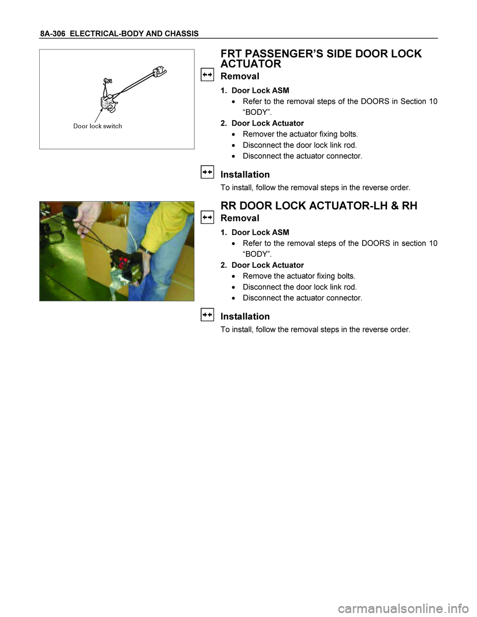
FRT PASSENGER’S SIDE DOOR LOCK
ACTUATOR
Removal
1. Door Lock ASM
� Refer to the removal steps of the DOORS in Section 10
“BODY”.
2. Door Lock Actuator
� Remover the actuator fixing bolts.
� Disconnect the door lock link rod.
� Disconnect the actuator connector.
Installation
To install, follow the removal steps in the reverse order.
RR DOOR LOCK ACTUATOR-LH & RH
Removal
1. Door Lock ASM
� Refer to the removal steps of the DOORS in section 10
“BODY”.
2. Door Lock Actuator
� Remove the actuator fixing bolts.
� Disconnect the door lock link rod.
� Disconnect the actuator connector.
Installation
To install, follow the removal steps in the reverse order.
Page 965 of 4264
ELECTRICAL-BODY AND CHASSIS 8A-307
INSPECTION AND REPAIR
Harness side
D-20 D-5
Driver Seat Side Power Window & Door Lock
Switch
1. Harness Side Connector Circuit
Check voltage and continuity between the switch harness
side connector terminals as shown in the following table.
Terminal
No. Wire
color Connecting to Check itemConnectin
g terminalCheck condition Standard
Door lock SW
Driver seat Lock Continuity
(Lock) side door
Unlock No continuity
Door lock SW
Driver seat Lock No continuity
(Unlock) side door
Unlock Continuity
3 (D-5) L/R Ground
Continuity 3-Ground - Continuity
4 (D-5)
L/R Door lock
actuator (Lock) (Resistance)
4-5
- Continuity
There is some
resistance
5 (D-5)
L Door lock
actuator
(Unlock)
5-4
- Continuity
There is some
resistance
1 (D-5) LG/W Fuse
C-14 (20A) Voltage 1- Ground - Battery voltage
(Approx. 12V)
14-Ground L/R 14 (D-20)
13-Ground L/Y
13 (D-20)
Page 966 of 4264
8A-308 ELECTRICAL-BODY AND CHASSIS
Harness side
D-20 D-5
2. Switch Side Connector Circuit
Remove the switch connector, and check continuity and
voltage between the switch connector terminals.
(Connect the (+) terminal of the battery to 1
D-5and the
(-) terminal to 3
D-5.)
3
D-5 - 4 D-5.................. Continuity
3 D-5 - 5 D-5.................. Continuity
(Then, ground 3 D-5.)
4
D-5........... Current flow for approx. 1 second
(Disconnect the ground of 14 D-20 , and ground 13 D-20.)
5
D-5........... Current flow for approx. 1 second
Harness side
D-5
3. Door Lock Operation Test
After confirming that there is continuity between the switch
harness side connector terminals 4
D-5 and 5 D-5,
apply the battery voltage to each of the terminals to conduc
t
the operation test.
When the door lock will not operate, check the door lock
actuator for any trouble.
Connecting terminals
5 (L) 4 (L/R)
+ - Unlock
- + Lock
Operation
Page 967 of 4264

ELECTRICAL-BODY AND CHASSIS 8A-309
Switch side
D-4
Driver’s Side Door Lock Switch
1. Switch Side Connector Circuit
Check continuity between the switch connector terminals
Terminal No.
SW position 1 2 3
Lock
Unlock
Actuator side
D-9
Front Passenger’s Side Door Lock Actuator
1. Actuator Side Connector Circuit
Apply the battery voltage to the actuator connector
terminals to check the operation.
When the door lock actuator is checked on the vehicle and
there is no continuity, and when the door lock actuator itsel
f
is checked and no trouble is found, check the circuit
between the door lock actuator and the driver seat side
power window & door lock switch for any failure.
Connecting terminals
1 2
+ - Lock
- + Unlock
Operation
Actuator side
D-14 D-18
Rear Door Lock Actuator -LH & RH
1. Actuator Side Connector Circuit
Apply the battery voltage to the actuator connector
terminals to check the operation.
When the door lock actuator is checked on the vehicle and
there is no continuity, and when the door lock actuator itsel
f
is checked and no trouble is found, check the circuit
between the door lock actuator and the driver seat side
power window & door lock switch for any failure.
Connecting terminals
1 2
+ - Lock
- + Unlock
Operation
Page 974 of 4264

8A-316 ELECTRICAL-BODY AND CHASSIS
TROUBLESHOOTING
QUICK CHART FOR CHECK POINTS
Check Points
Trouble Mode Power Window & Door
Lock Switch Power Window
Switch Power Window Motor
Driver’s
Side Passenger’s
Side RR-LH RR-
RH Driver’s
Side Passenger’s
Side RR-LH RR-
RH
All windows will not operate Lock SW does not function Driver’s Window:
Window does not operate One-touch operation for
“DOWN” movement will not
operate
Window operates in only
one direction
Front window on passenger
seat side:
Window does not operate Window does not operate
when operating the driver’s
SW
Window does not operate
when operating the
passenger’s SW
Window does operate in
only one direction when
operating the driver’s SW
Window does operate in
only one direction when
operating the passenger’s
seat side SW
Rear window on left (or right)
side:
Window on left (or right)
side does not operate
Window does not operate
when operating the driver’s
SW
Window does operate in
only one direction when
operating the driver’s SW
Window does operate in
only one direction when
operating the RR-LH (or
RH) side SW
Cable
Harness Relay;
Power
Window
SBF-9
SBF-11