Page 3480 of 4264
3B-50 POWER-ASSISTED STEERING SYSTEM
CAUTION: The wheels of the vehicle must be
straight ahead and the steering column in the
"LOCK" position before disconnecting the steering
wheel. Failure to do so will cause the coil assembly
to become uncentered which will cause damage to
the coil assembly. (with SRS air bag)
5. Remove the engine hood opening lever and
steering lower cover.
6. Remove driver knee bolster (reinforcement).
7. Disable the SRS (Refer to "Disabling the SRS" in
this section). (with SRS air bag)
8. Check the both side hole of the steering cover. (with
SRS air bag)
060R300025
9. Check the position of the pins in a hole. Push the
pin in the direction of an arrow. (with SRS air bag)
060R300032
10. Push the four pins at �
5�
6 mm bar. (with SRS ai
r
bag)
060R300031
11. Cancel the lock four pins. (with SRS air bag)
12. Loosen the horn pad fixing screw at the rear of the
steering wheel (without SRS air bag).
430R300009
Page 3486 of 4264
3B-56 POWER-ASSISTED STEERING SYSTEM
CAUTION: The wheel of the vehicle must be straight
ahead and the steering column in the "LOCK"
position before disconnecting the steering column
from the steering gear. Failure to do so will cause
the SRS coil assembly to become uncentered which
will cause damage to the SRS coil assembly. (with
SRS air bag)
5. Remove the engine hood opening lever and
steering lower cover.
6. Remove the driver knee bolster (reinforcement).
7. Disable the SRS (Refer to "Disabling the SRS" in
this section). (with SRS air bag)
8. Check the both side hole of the steering cover. (with
SRS air bag)
060R300025
9. Check the position of the pins in a hole. Push the
pin in the direction of an arrow. (with SRS air bag)
060R300032
10. Push the four pins at �
5�
6 mm bar. (with SRS ai
r
bag)
060R300031
11. Cancel the lock four pins. (with SRS air bag)
12. Loosen the horn pad fixing screw at the rear of the
steering wheel (without SRS air bag).
430R300009
Page 3488 of 4264
3B-58 POWER-ASSISTED STEERING SYSTEM
16. Remove steering column cover.
17. Disconnect the wiring harness connectors located
under the steering column.
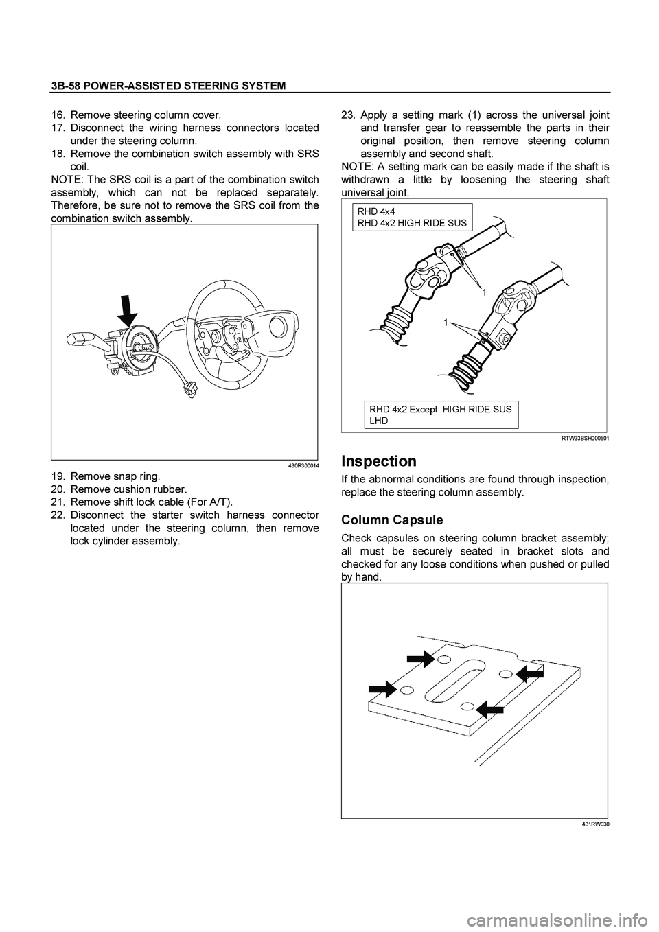
18. Remove the combination switch assembly with SRS
coil.
NOTE: The SRS coil is a part of the combination switch
assembly, which can not be replaced separately.
Therefore, be sure not to remove the SRS coil from the
combination switch assembly.
430R300014
19. Remove snap ring.
20. Remove cushion rubber.
21. Remove shift lock cable (For A/T).
22. Disconnect the starter switch harness connecto
r
located under the steering column, then remove
lock cylinder assembly.
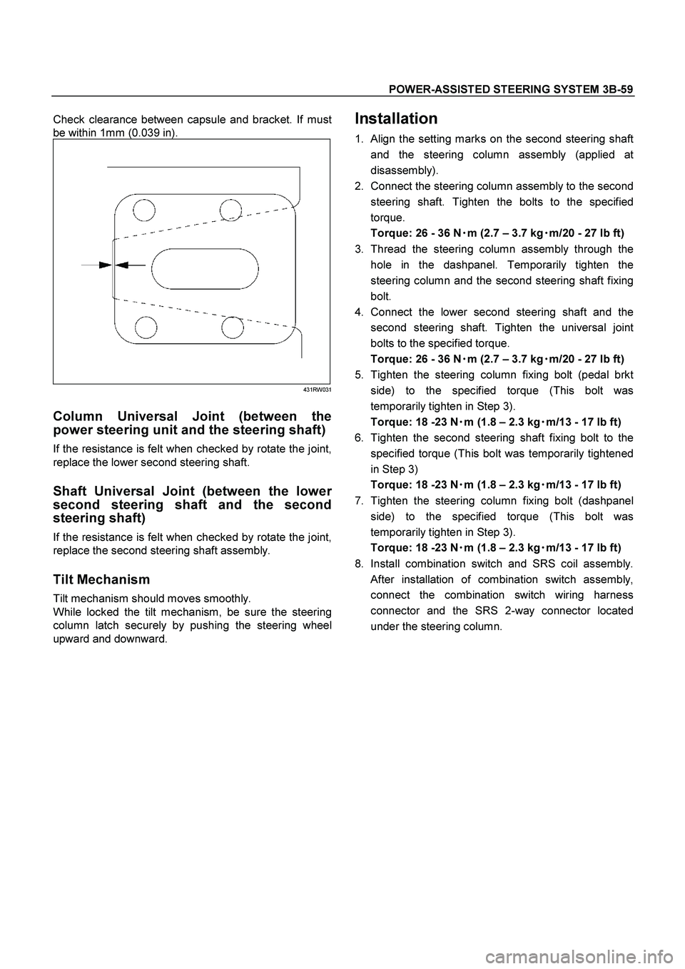
23.
Apply a setting mark (1) across the universal joint
and transfer gear to reassemble the parts in thei
r
original position, then remove steering column
assembly and second shaft.
NOTE: A setting mark can be easily made if the shaft is
withdrawn a little by loosening the steering shaft
universal joint.
RTW33BSH000501
Inspection
If the abnormal conditions are found through inspection,
replace the steering column assembly.
Column Capsule
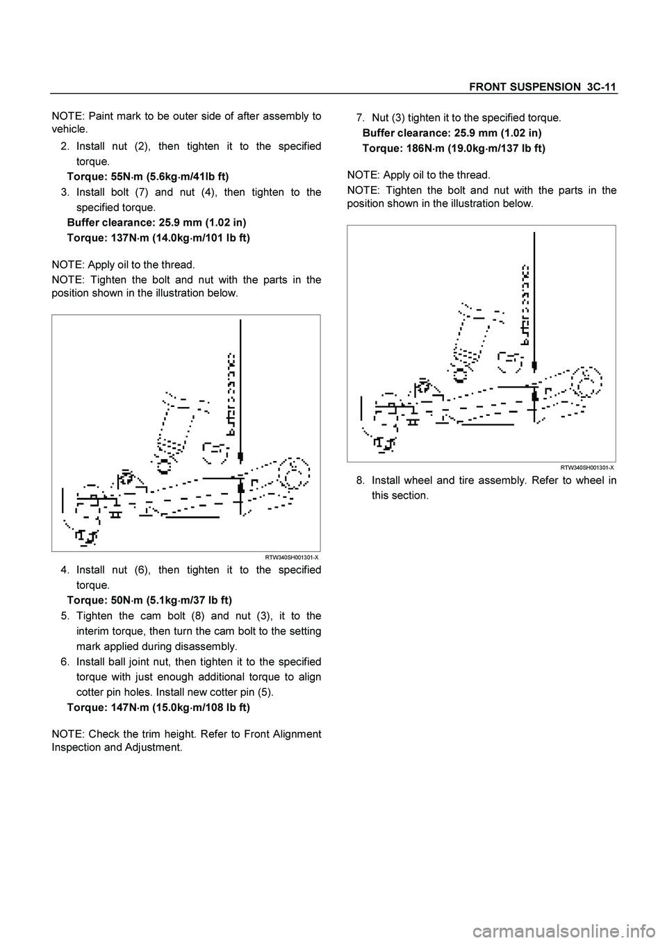
Check capsules on steering column bracket assembly;
all must be securely seated in bracket slots and
checked for any loose conditions when pushed or pulled
by hand.
431RW030
Page 3489 of 4264
POWER-ASSISTED STEERING SYSTEM 3B-59
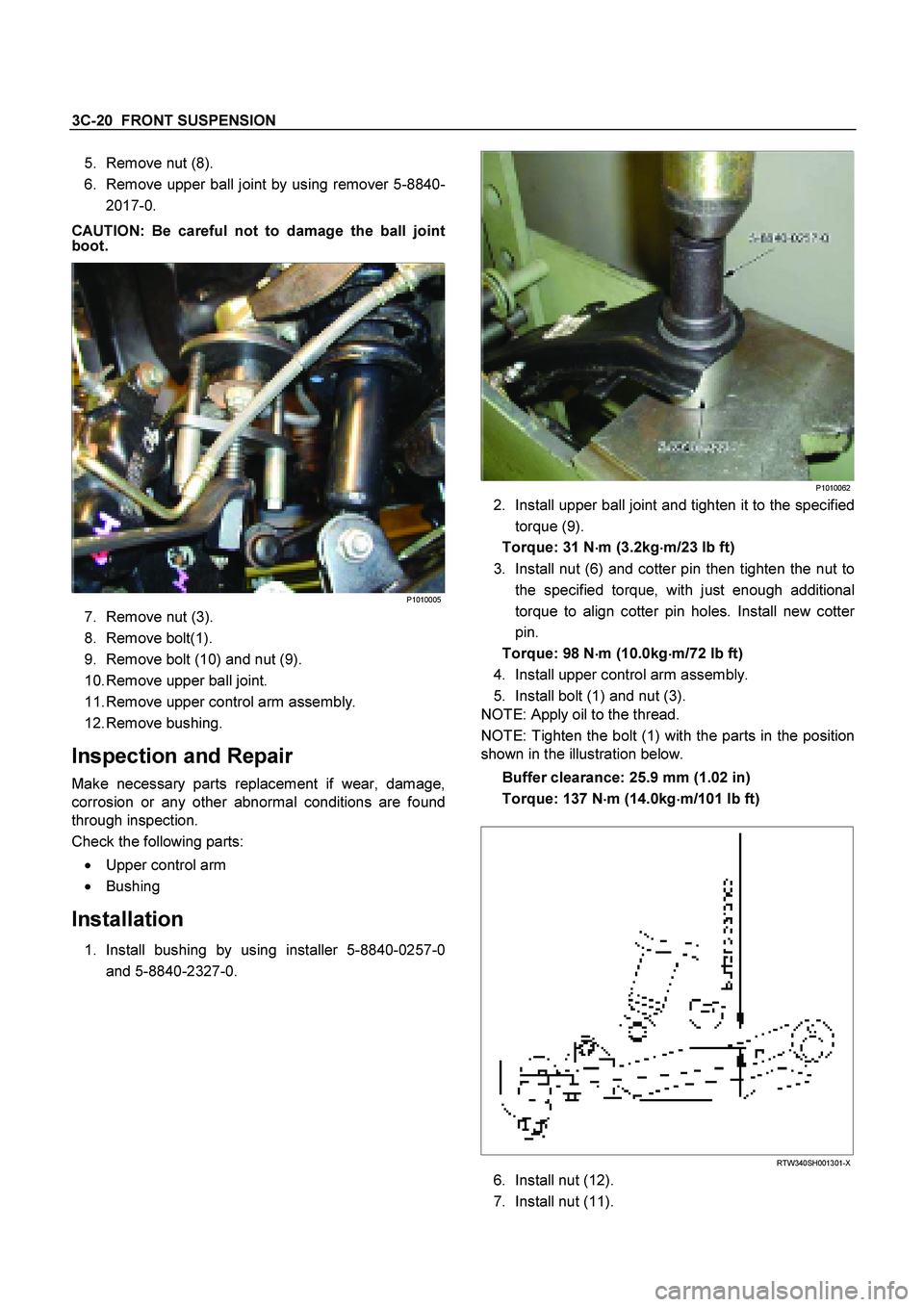
Check clearance between capsule and bracket. If must
be within 1mm (0.039 in).
431RW031
Column Universal Joint (between the
power steering unit and the steering shaft)
If the resistance is felt when checked by rotate the joint,
replace the lower second steering shaft.
Shaft Universal Joint (between the lower
second steering shaft and the second
steering shaft)
If the resistance is felt when checked by rotate the joint,
replace the second steering shaft assembly.
Tilt Mechanism
Tilt mechanism should moves smoothly.
While locked the tilt mechanism, be sure the steering
column latch securely by pushing the steering wheel
upward and downward.
Installation
1. Align the setting marks on the second steering shaft
and the steering column assembly (applied at
disassembly).
2. Connect the steering column assembly to the second
steering shaft. Tighten the bolts to the specified
torque.
Torque: 26 - 36 N�
�� �m (2.7 – 3.7 kg�
�� �m/20 - 27 lb ft)
3. Thread the steering column assembly through the
hole in the dashpanel. Temporarily tighten the
steering column and the second steering shaft fixing
bolt.
4. Connect the lower second steering shaft and the
second steering shaft. Tighten the universal joint
bolts to the specified torque.
Torque: 26 - 36 N�
�� �m (2.7 – 3.7 kg�
�� �m/20 - 27 lb ft)
5. Tighten the steering column fixing bolt (pedal brkt
side) to the specified torque (This bolt was
temporarily tighten in Step 3).
Torque: 18 -23 N�
�� �m (1.8 – 2.3 kg�
�� �m/13 - 17 lb ft)
6. Tighten the second steering shaft fixing bolt to the
specified torque (This bolt was temporarily tightened
in Step 3)
Torque: 18 -23 N�
�� �m (1.8 – 2.3 kg�
�� �m/13 - 17 lb ft)
7. Tighten the steering column fixing bolt (dashpanel
side) to the specified torque (This bolt was
temporarily tighten in Step 3).
Torque: 18 -23 N�
�� �m (1.8 – 2.3 kg�
�� �m/13 - 17 lb ft)
8. Install combination switch and SRS coil assembly.
After installation of combination switch assembly,
connect the combination switch wiring harness
connector and the SRS 2-way connector located
under the steering column.
Page 3503 of 4264
FRONT SUSPENSION 3C-11
NOTE: Paint mark to be outer side of after assembly to
vehicle.
2. Install nut (2), then tighten it to the specified
torque.
Torque: 55N
�
�� �m (5.6kg
�
�� �m/41lb ft)
3. Install bolt (7) and nut (4), then tighten to the
specified torque.
Buffer clearance: 25.9 mm (1.02 in)
Torque: 137N�
�� �m (14.0kg�
�� �m/101 lb ft)
NOTE: Apply oil to the thread.
NOTE: Tighten the bolt and nut with the parts in the
position shown in the illustration below.
RTW340SH001301-X
4. Install nut (6), then tighten it to the specified
torque.
Torque: 50N�
�� �m (5.1kg�
�� �m/37 lb ft)
5. Tighten the cam bolt (8) and nut (3), it to the
interim torque, then turn the cam bolt to the setting
mark applied during disassembly.
6. Install ball joint nut, then tighten it to the specified
torque with just enough additional torque to align
cotter pin holes. Install new cotter pin (5).
Torque: 147N�
�� �m (15.0kg�
�� �m/108 lb ft)
NOTE: Check the trim height. Refer to Front Alignment
Inspection and Adjustment.
7. Nut (3) tighten it to the specified torque.
Buffer clearance: 25.9 mm (1.02 in)
Torque: 186N�
�� �m (19.0kg�
�� �m/137 lb ft)
NOTE: Apply oil to the thread.
NOTE: Tighten the bolt and nut with the parts in the
position shown in the illustration below.
RTW340SH001301-X
8. Install wheel and tire assembly. Refer to wheel in
this section.
Page 3505 of 4264
FRONT SUSPENSION 3C-13
Disassembly
1. Install the support fixture (5-8840-0595-0) to the base (5-
8840-003-0).
2. Install the upper adapter (5-8840-0597-0) and the lower
adapter (5-8840-0596-0) to the base and support fixture
assembly.
3. Install the shock absorber assembly to the support fixture.
4. Remove the nut with spring in place.
CAUTION:
Take care not to apply excessive force to the nut during
removal.
CAUTION :
The shock absorbers have been charged with gas at the
factory. Exposure to high temperatures or an open flame
can result in a dangerous explosion.
Keep the shock absorbers away from high temperatures
and open flames.
INSPECTION AND REPAIR
Make all necessary adjustments, repairs, and part replacements if wear, damage, or other problems are discovered
during inspections.
Visual Check
Inspect the following parts for wear, damage or other abnormal
conditions.
�
Shock absorber
�
Rubber bushing
�
Coil spring
Page 3512 of 4264
3C-20 FRONT SUSPENSION
5. Remove nut (8).
6. Remove upper ball joint by using remover 5-8840-
2017-0.
CAUTION: Be careful not to damage the ball joint
boot.
P1010005
7. Remove nut (3).
8. Remove bolt(1).
9. Remove bolt (10) and nut (9).
10. Remove upper ball joint.
11. Remove upper control arm assembly.
12. Remove bushing.
Inspection and Repair
Make necessary parts replacement if wear, damage,
corrosion or any other abnormal conditions are found
through inspection.
Check the following parts:
�
Upper control arm
�
Bushing
Installation
1. Install bushing by using installer 5-8840-0257-0
and 5-8840-2327-0.
P1010062
2. Install upper ball joint and tighten it to the specified
torque (9).
Torque: 31 N �
��
�
m (3.2kg �
��
�
m/23 lb ft)
3. Install nut (6) and cotter pin then tighten the nut to the specified torque, with just enough additional
torque to align cotter pin holes. Install new cotte
r
pin.
Torque: 98 N �
��
�
m (10.0kg
�
��
�
m/72 lb ft)
4. Install upper control arm assembly.
5. Install bolt (1) and nut (3).
NOTE: Apply oil to the thread.
NOTE: Tighten the bolt (1) with the parts in the position
shown in the illustration below.
Buffer clearance: 25.9 mm (1.02 in)
Torque: 137 N �
��
�
m (14.0kg �
��
�
m/101 lb ft)
RTW340SH001301-X
6. Install nut (12).
7. Install nut (11).
Page 3514 of 4264
3C-22 FRONT SUSPENSION
4. Support lower control arm with a jack.
5. Remove the nut (10).
6. Remove the nut (8).
7. Remove the shock absorber lower end from the
lower control arm.
8. Remove the lower ball joint from the lower control arm.
9. Remove nut (4) and cam plate.
10. Remove cam bolt.
11. Remove lower control arm.
12. Remove bushing.
Inspection and Repair
Make necessary correction or parts replacement if
wear, damage, corrosion or any other abnormal
condition are found through inspection.
Check the following parts:
�
Lower control arm
�
Bushing
Installation
1. Install rear bushing by using installer 5-8840-
0257-0 and 5-8840-2327-0.
P1010063
2. Install lower control arm.
3. Install cam bolt.
4. Install lower ball joint and tighten it to the specified
torque (9).
Torque: 127 N �
��
�
m (12.9kg �
��
�
m/94 lb ft)
5. Install shock absorber and tighten it to the specified torque (5).
NOTE: Apply oil to the thread.
NOTE: Tighten the nut (4) with the parts in the position
shown in the illustration below.
Torque: 137 N �
��
�
m (14.0kg �
��
�
m/101 lb ft)
RTW340SH001301-X
6. Install stabilizer link and tighten it to the specified
torque (10).
Torque: 50 N �
��
�
m (5.1kg �
��
�
m/37 lb ft)
7. Install nut (4) and cam plate and tighten lower link nut finger-tight.
NOTE: Apply oil to the thread.
NOTE: Tighten the nut (4) with the parts in the position
shown in the illustration below.
Buffer clearance: 25.9 mm (1.02 in)
Torque: 186 N �
��
�
m (19.0kg �
��
�
m/137 lb ft)
RTW340SH001301-X
8. Install nut (8) and cotter pin then tighten the nut to
the specified torque, with just enough additional
torque to align cotter pin holes. Install new cotte
r