Page 3086 of 4264
1-76 HEATER AND AIR CONDITIONING
INSPECTION AND REPAIR
840R300005-X
Resistor
As for air-conditioning model, fixed on left (RHD) / right (LHD)
side of the evaporator unit.
As for heater only model, fixed on left (RHD) / right (LHD) side
of the duct placed between blower unit and heater unit.
Replace the resistor with a new on if the coil is found to be
open or if the resistance value deviates from the specified
range.
Terminal Resistance
3 – 2 1.99 �
3 – 4 0.9 �
3 – 1 0.17 �
Blower motor
Check blower motor for smooth rotation.
Connect the battery positive terminal to the No.1 terminal of the
blower motor and negative to the No.2.
Be sure to check to see if the blower motor operates correctly.
Page 3093 of 4264

HEATER AND AIR CONDITIONING 1-83
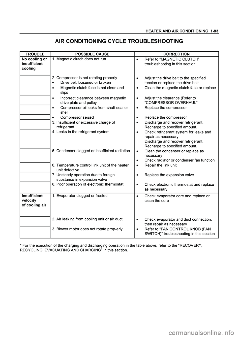
AIR CONDITIONING CYCLE TROUBLESHOOTING
TROUBLE POSSIBLE CAUSE CORRECTION
No cooling or
insufficient
cooling
1. Magnetic clutch does not run
��
Refer to “MAGNETIC CLUTCH”
troubleshooting in this section
2. Compressor is not rotating properly
��Drive belt loosened or broken ��
Adjust the drive belt to the specified
tension or replace the drive belt
��Magnetic clutch face is not clean and
slips ��Clean the magnetic clutch face or replace
��
Incorrect clearance between magnetic
drive plate and pulley ��
Adjust the clearance (Refer to
“COMPRESSOR OVERHAUL”
��
Compressor oil leaks from shaft seal or
shell ��
Replace the compressor
��
Compressor seized ��
Replace the compressor
3. Insufficient or excessive charge of
refrigerant ��
Discharge and recover refrigerant.
Recharge to specified amount.
4. Leaks in the refrigerant system
��
Check refrigerant system for leaks and
repair as necessary
Discharge and recover refrigerant.
Recharge to specified amount.
5. Condenser clogged or insufficient radiation
��Clean the condenser or replace as
necessary
��
Check radiator or condenser fan function
6. Temperature control link unit of the heater
unit defective ��
Repair the link unit
7. Unsteady operation due to foreign
substance in expansion valve ��
Replace the expansion valve
8. Poor operation of electronic thermostat
��
Check electronic thermostat and replace
as necessary
Insufficient
velocity
of cooling air
1. Evaporator clogged or frosted
��
Check evaporator core and replace or
clean the core
2. Air leaking from cooling unit or air duct
��Check evaporator and duct connection,
then repair as necessary
3. Blower motor does not rotate prop-erly
��
Refer to “FAN CONTROL KNOB (FAN
SWITCH)” troubleshooting in this section
* For the execution of the charging and discharging operation in the table above, refer to the “RECOVERY,
RECYCLING, EVACUATING AND CHARGING” in this section.
Page 3208 of 4264

7B1-44 MANUAL TRANSMISSION
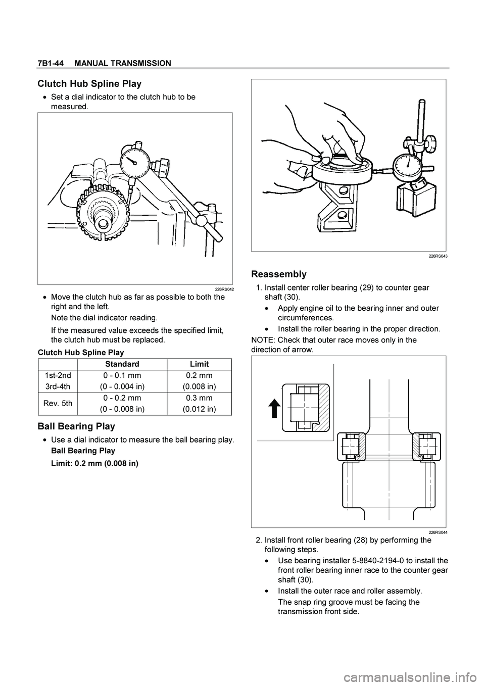
Clutch Hub Spline Play
� Set a dial indicator to the clutch hub to be
measured.
226RS042
�
Move the clutch hub as far as possible to both the
right and the left.
Note the dial indicator reading.
If the measured value exceeds the specified limit,
the clutch hub must be replaced.
Clutch Hub Spline Play
Standard Limit
1st-2nd
3rd-4th 0 - 0.1 mm
(0 - 0.004 in) 0.2 mm
(0.008 in)
Rev. 5th 0 - 0.2 mm
(0 - 0.008 in) 0.3 mm
(0.012 in)
Ball Bearing Play
�
Use a dial indicator to measure the ball bearing play.
Ball Bearing Play
Limit: 0.2 mm (0.008 in)
226RS043
Reassembly
1. Install center roller bearing (29) to counter gear
shaft (30).
�
Apply engine oil to the bearing inner and outer
circumferences.
� Install the roller bearing in the proper direction.
NOTE: Check that outer race moves only in the
direction of arrow.
226RS044
2. Install front roller bearing (28) by performing the
following steps.
� Use bearing installer 5-8840-2194-0 to install the
front roller bearing inner race to the counter gear
shaft (30).
�
Install the outer race and roller assembly.
The snap ring groove must be facing the
transmission front side.
Page 3209 of 4264

MANUAL TRANSMISSION 7B1-45
�
Use bearing installer 5-8840-2194-0 to install the
ring.
RTW47BSH000501
Legend
(1) Ring
(2) Outer Race and Roller Assembly
(3) Inner Race
3. Install bearing snap ring (27) to counter gear shaft
(30).
4. Apply engine oil to the needle bearing (25) and the
2nd gear (24) thrust surfaces.
Install the needle bearing (25) and the 2nd gear (24)
to the mainshaft (26).
The 2nd gear (24) dog teeth must be facing the
transmission rear side.
226RS046
5. Assemble 2nd inside ring (23), 2nd outside ring (22),
and 2nd block ring (21) on 2nd gear (24).
�
Apply engine oil to the synchronizer ring friction
surfaces.
226RS047
Legend
(1) Block Ring
(2) Outside Ring
(3) Inside Ring
(4) 2nd Gear
(5) Needle Bearing
6. Assemble 1st-2nd synchronizer assembly (20) by
performing the following steps:
1. Check that the inserts (3) fit snugly into the
clutch hub (5) insert grooves.
2. Check that the inserts springs (4) are fitted to
the inserts as shown in the illustration.
3. Check that the clutch hub (5) and the sleeve (6)
slide smoothly.
Page 3212 of 4264

7B1-48 MANUAL TRANSMISSION
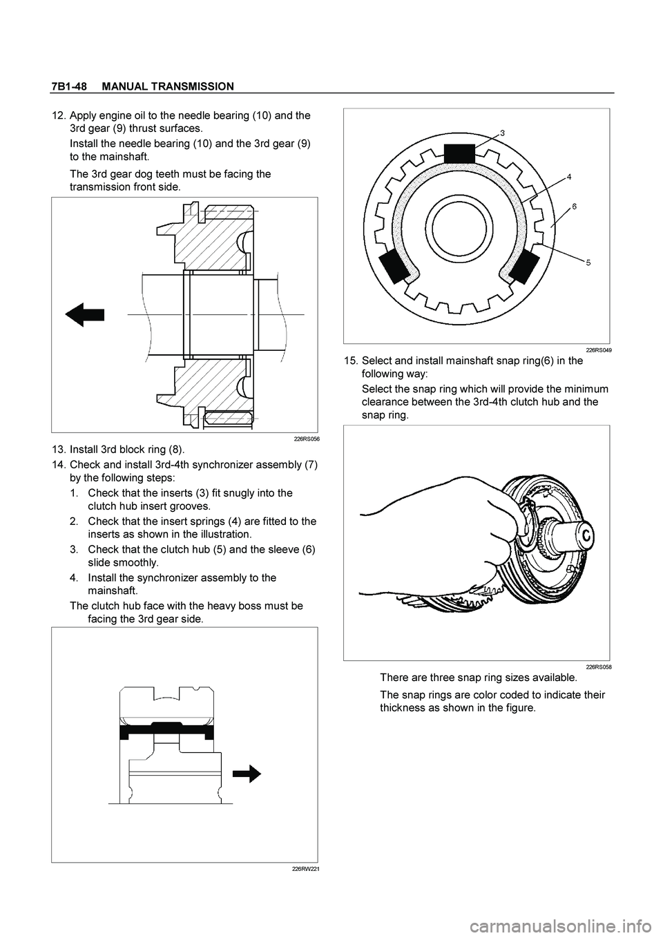
12. Apply engine oil to the needle bearing (10) and the
3rd gear (9) thrust surfaces.
Install the needle bearing (10) and the 3rd gear (9)
to the mainshaft.
The 3rd gear dog teeth must be facing the
transmission front side.
226RS056
13. Install 3rd block ring (8).
14. Check and install 3rd-4th synchronizer assembly (7)
by the following steps:
1. Check that the inserts (3) fit snugly into the
clutch hub insert grooves.
2. Check that the insert springs (4) are fitted to the
inserts as shown in the illustration.
3. Check that the clutch hub (5) and the sleeve (6)
slide smoothly.
4. Install the synchronizer assembly to the
mainshaft.
The clutch hub face with the heavy boss must be
facing the 3rd gear side.
226RW221
226RS049
15. Select and install mainshaft snap ring(6) in the
following way:
Select the snap ring which will provide the minimum
clearance between the 3rd-4th clutch hub and the
snap ring.
226RS058
There are three snap ring sizes available.
The snap rings are color coded to indicate their
thickness as shown in the figure.
Page 3218 of 4264
7B1-54 MANUAL TRANSMISSION
TROUBLESHOOTING
1. ABNORMAL NOISE
1) NOISY IN NEUTRAL
Checkpoint Trouble Cause Countermeasure
Replenish or replace the gear
oilInsufficient or improper gear
oil NG
Mainshaft splines
Synchronizer clutch hub
splinesReplace the main shaft and
the synchronizer clutch hub
Replace the gear(s)
Replace the flywheel pilot
Worn splines
Worn or scuffed gear tooth
contact surfaces
Flywheel pilot bearingWorn flywheel pilot bearing
Bearings (Mainshaft,
countershaft, and transfer
shaft)
Gears (Mainshaft,
countershaft, reverse idler
gear and transfer gears)
Replace the bearing(s)Worn or broken bearing(s)
OK
NG NG NG NG OK
OK
OK
Gear oil
TransmissionRealign the transmissionTransmission misalignment OK
NG
Page 3219 of 4264
MANUAL TRANSMISSION 7B1-55
2) NOISY OPERATION
Checkpoint Trouble Cause Countermeasure
Replenish or replace the gear
oilInsufficient or improper engine
oil NG
Replace the gear(s)
Replace the gear(s)
Replace the bearing(s)
Gears (Gear whining)Lack of backlash between
meshing gears
Free running gears seizing on
the thrust face or the inner
face
Bearings (Hissing, thumping
or bumping)Worn or broken bearing(s)
Gears (Squealing at high
speeds)
Replace the gear(s)Gears (Growling, humming, or
grinding)Worn, chipped, or cracked
gear(s)
NG NG NG NG OK
OK
OK OK
Gear oil (Metallic rattling)
Page 3220 of 4264
7B1-56 MANUAL TRANSMISSION
2. HARD SHIFTING
Checkpoint Trouble Cause Countermeasure
Change lever play
Clutch pedal free play
Repair or replace the
applicable parts and regrease
Readjust the clutch pedal free
play
Worn change lever sliding
portions
Improper clutch pedal free
play
Change lever operationRepair or regrease the change
lever assembly
Replenish or replace the
engine oil
Hard operating change lever
caused insufficient grease
Insufficient or improper gear
oil
OK
OKNG NG NG NG
OK OKGear oil
Continued on the next page
Shift rod and quadrant box
sliding faces, and other partsReplace the shidt rod and/or
the quadrant boxWorn shift rod and/or sliding
faces
Repair or replace the sleeveSleeve movement failure
NG NG
OKShift block sleeve movement