Page 3771 of 4264

ON-VEHICLE SERVICE (AW30 –40LE) 7A3-15
Measure Line Pressure
1. Fully apply the parking brake and chock the four
wheels.
2. Start the engine and check idling rpm.
3. Shift into “D" range, step down strongly on the brake
pedal with your left foot and, while manipulating the
accelerator pedal with the right foot, measure the
line pressures at the engine speeds specified in the
table.
4. In the same manner, perform the test in “R" range.
Line pressure kPa (kg/cm2/psi) Engine
speed “D" range “R" range
Idling 323 – 382
(3.3 – 3.9/47 – 55) 500 – 598
(5.1 – 6.1/73 – 87)
Stall 1,137 – 1,274 (11.6–13.0/165–185) 1,499 – 1,833
(15.3–18.7/218–266)
Evaluation
1. If the measured values at all ranges are higher than
specified:
Pressure control solenoid defective
Primary regulator valve defective
2. If the measured values at all ranges are lower than
specified:
Primary regulator valve defective
Oil pump defective
Pressure control solenoid defective
3. If pressure is low in “D" range only:
“ D" range circuit fluid leakage
4. If pressure is low in “R" range only:
“ R" range circuit fluid leakage
Road Test
NOTE: Perform the test at normal operation fluid
temperature (50 – 80 �
C or 122 – 176 �
F).
“D" Range Test in “NORMAL", and
“POWER" Pattern Ranges
Shift into the “D" range and hold the accelerator pedal
constant at the 50% and 100% throttle valve opening
positions.
Push in one of the pattern selector buttons and check
the following:
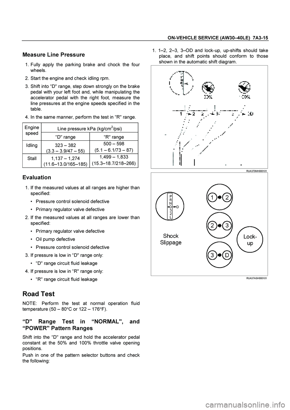
1. 1 –2, 2 –3, 3 –OD and lock-up, up-shifts should take
place, and shift points should conform to those
shown in the automatic shift diagram.
RUA370MH000101
RUA37ASH000101
Page 3778 of 4264
7A3-22 ON-VEHICLE SERVICE (AW30 –40LE)
ATF Replacement
Inspection
NOTE: Do not overfill.
1. Remove the drain plug from oil pan and drain the
fluid.
RUW17ASH013401
2. Reinstall the drain plug securely.
Torque: 19 N �
��
�
m (14 Ib ft)
3. With the engine OFF, add new fluid through the fille
r
tube.
Drain and refill 5.2 liter
Dry fill 8.7 liter
Fluid BESCO ATF III
4. Start the engine and shift the selector into all
position from “P" through “L", and then shift into “P".
5. With the engine idling, check the fluid level. Add fluid up to the “COLD" level on the dipstick.
6. The ATF level must be checked again for correct level with the “HOT" level.
NOTE: To prevent fluid leaks, the drain plug gasket
must be replaced each time this plug is removed.
Page 3782 of 4264

7A3-26 ON-VEHICLE SERVICE (AW30 –40LE)
Solenoid
Inspection
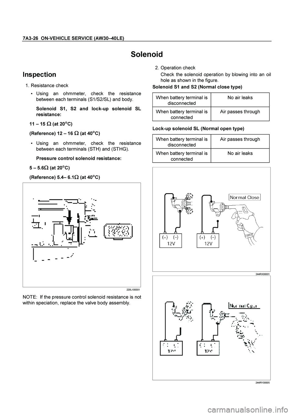
1. Resistance check
Using an ohmmeter, check the resistance
between each terminals (S1/S2/SL) and body.
Solenoid S1, S2 and lock-up solenoid SL
resistance:
11 – 15
�
� �
� (at 20�
� �
�C)
(Reference) 12 – 16
�
� �
� (at 40�
� �
�C)
Using an ohmmeter, check the resistance
between each terminals (STH) and (STHG).
Pressure control solenoid resistance:
5 – 5.6
�
� �
� (at 20�
� �
�C)
(Reference) 5.4 – 6.1
�
� �
� (at 40�
� �
�C)
220L100001
NOTE: If the pressure control solenoid resistance is not
within speciation, replace the valve body assembly.
2. Operation check
Check the solenoid operation by blowing into an oil
hole as shown in the figure.
Solenoid S1 and S2 (Normal close type)
When battery terminal is disconnected No air leaks
When battery terminal is
connected Air passes through
Lock-up solenoid SL (Normal open type)
When battery terminal is disconnected Air passes through
When battery terminal is
connected No air leaks
244RX00001
244RY00005
Page 3794 of 4264
7A3-38 ON-VEHICLE SERVICE (AW30 –40LE)
2. Remove the oil strainer assembly.
244RY 00003
3. Disconnect the solenoid wiring connectors from the
solenoids.
4. Remove the twenty bolts from the valve body.
5. Remove the valve body assembly and pressure control solenoid.
After removing valve body assembly from the
transmission case, loosen the solenoid clamp
bolt and remove the pressure control solenoid
from the upper valve body assembly.
Also disconnect the harness connector from the
pressure control solenoid.
NOTE:
Two or more persons are required for removal and
installation of the valve body assembly and pressure
control solenoid.
The check valve assembly (1) and the C0
accumulator piston springs (2) will fall from the
transmission case during removal of valve bod
y
assembly.
Protect these parts from damage. The B0 (3), C2 (4),
and B2 (5) accumulator piston and springs may also
fall free and must be protected.
244RY00018
244RY00006
Page 3795 of 4264
ON-VEHICLE SERVICE (AW30 –40LE) 7A3-39
Installation
To install, follow the removal steps in reverse order
noting the following point;
1. Reinstall the parts removed with the valve bod
y
assembly to their assigned positions in the
transmission case (check valve assembly, C0
accumulator pistons, etc). Install the valve bod
y
assembly to the transmission case.
Refer to REASSEMBLY OF MAJO
R
COMPONENTS (2).
2. Solenoid clamp bolt
Torque : 7 N �
��
�
m (61 Ib in)
3. Valve body fixing bolts
Each bolt location and length (mm) is indicated in
the figure.
Torque : 10 N �
��
�
m (87 Ib in)
NOTE: Tighten the bolts toward outside equally.
244R200078
4. Oil strainer fixing bolts
Torque : 10 N �
��
�
m (87 Ib in)
5. Oil pan fixing bolts
Torque : 8 N �
��
�
m (69 Ib in)
Page 3799 of 4264

ON-VEHICLE SERVICE (AW30 –40LE) 7A3-43
Removal
NOTE: Before removing transmission and transfer
assembly from vehicle, change the transfer mode to
2WD using the 4WD push button switch on dash panel.
1. Disconnect battery ground cable.
2. Raise and support vehicle with suitable stands.
3. Remove front propeller shaft.(4WD only)
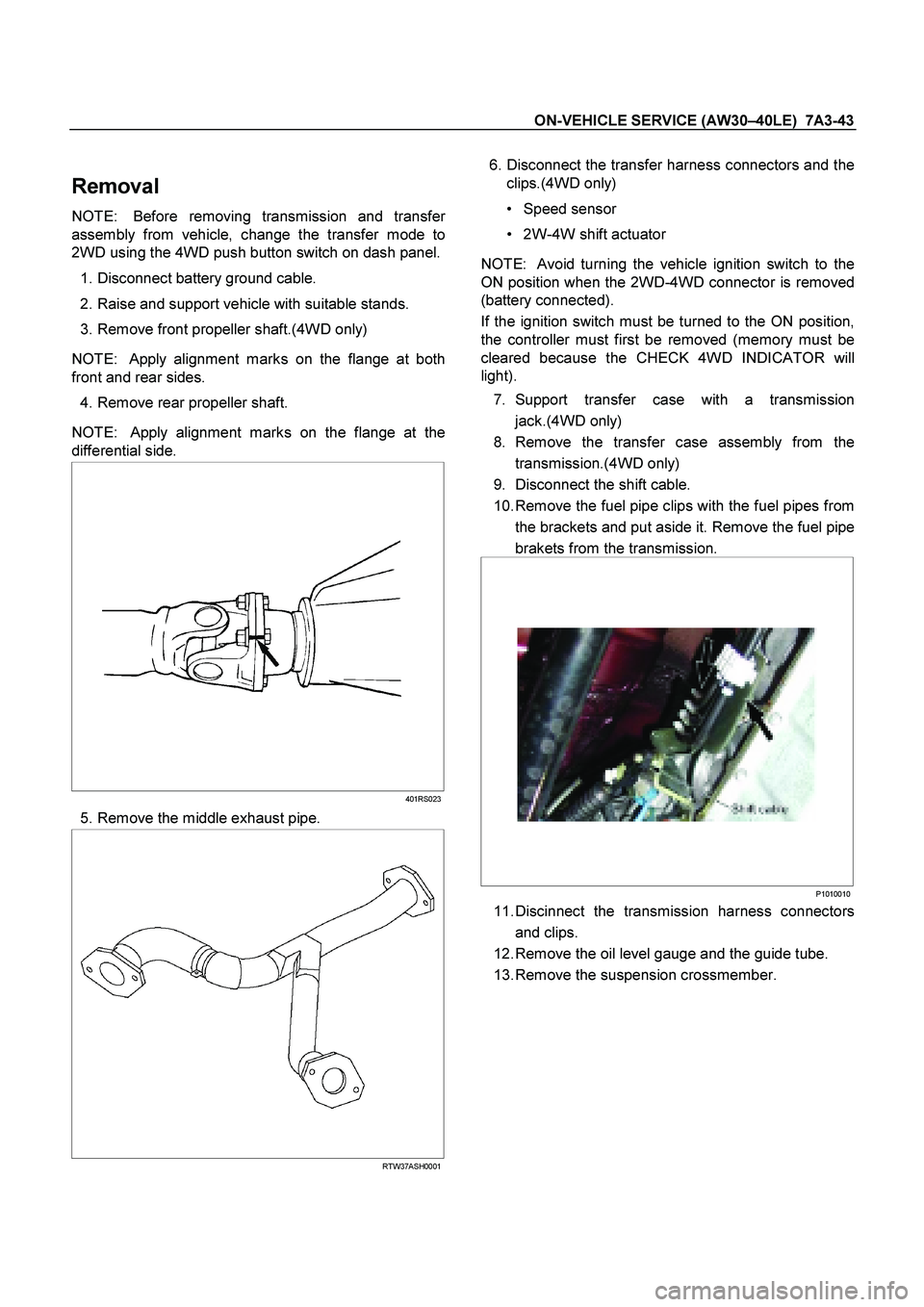
NOTE: Apply alignment marks on the flange at both
front and rear sides.
4. Remove rear propeller shaft.
NOTE: Apply alignment marks on the flange at the
differential side.
401RS023
5. Remove the middle exhaust pipe.
RTW37ASH0001
6. Disconnect the transfer harness connectors and the
clips.(4WD only)
Speed sensor
2W-4W shift actuator
NOTE: Avoid turning the vehicle ignition switch to the
ON position when the 2WD-4WD connector is removed
(battery connected).
If the ignition switch must be turned to the ON position,
the controller must first be removed (memory must be
cleared because the CHECK 4WD INDICATOR will
light).
7. Support transfer case with a transmission jack.(4WD only)
8. Remove the transfer case assembly from the
transmission.(4WD only)
9. Disconnect the shift cable.
10. Remove the fuel pipe clips with the fuel pipes from the brackets and put aside it. Remove the fuel pipe
brakets from the transmission.
P1010010
11. Discinnect the transmission harness connectors
and clips.
12. Remove the oil level gauge and the guide tube.
13. Remove the suspension crossmember.
Page 3815 of 4264
UNIT REPAIR (AW30–40LE) 7A4–7
Major Components (2)
Major Componets (2) and Associated Parts
RT W37 A LF00 0801
E nd O FCallo ut
Legend
(1) Converter housing
(2) Oil pan
(3) Oil strainer assembly
(4) Valve body
(5) Check valve, spring
(6) Spring
(7) Accumulator piston (B–2)
(8) Accumulator piston (C–2)(9) Accumulator piston (B–0)
(10) Accumulator piston (C–0)
(11) Second brake drum gasket
(12) Solenoid wiring
(13) Snap ring, rotor, key (4�4)
(14) Snap ring, speedometer sensor drive gear, ball
(4�2)
(15) Spacer, rotor, key, snap ring (4�2)
Page 3820 of 4264

7A4–12 UNIT REPAIR (AW30–40LE)
5. Install the second brake drum gasket.
Install a new second brake drum gasket to the
transmission case.
24 0RY 0 001 3
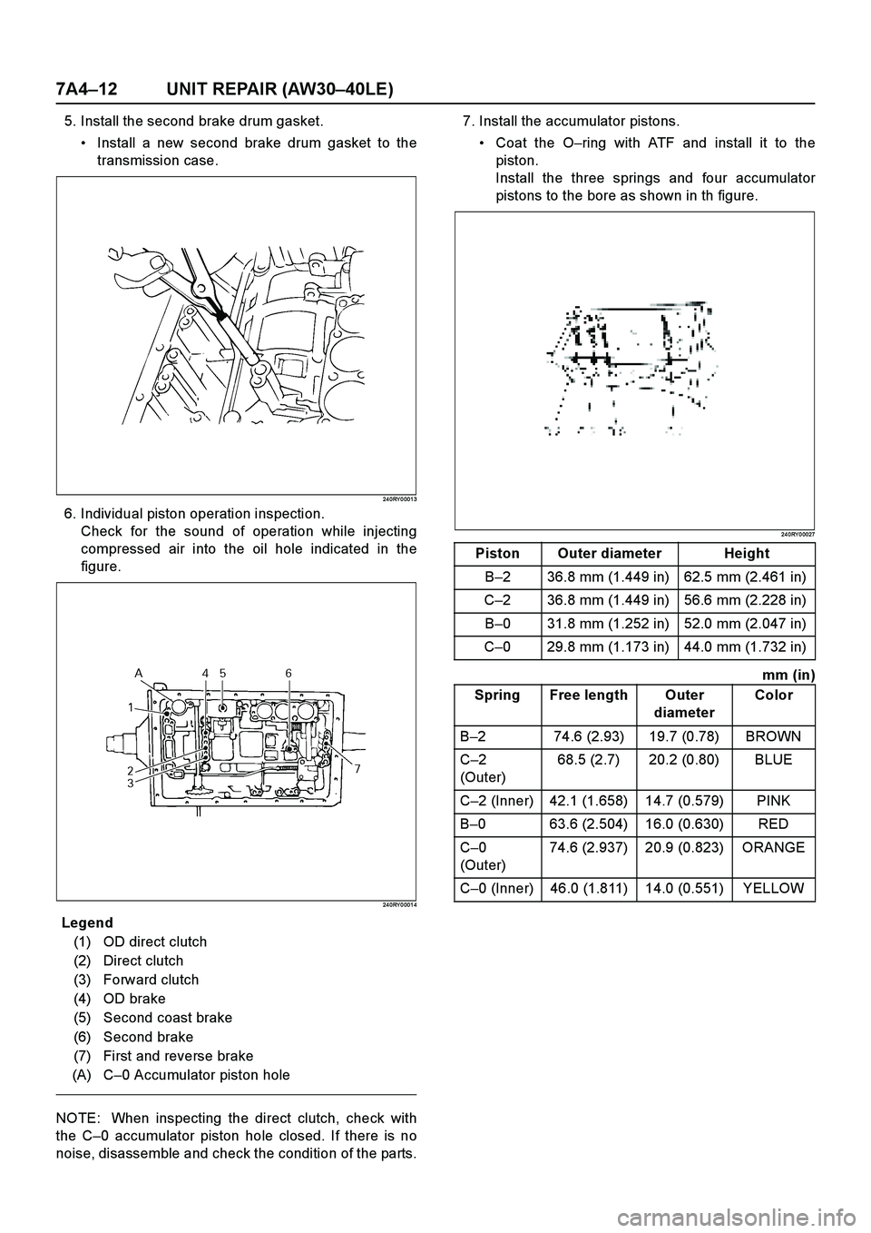
6. Individual piston operation inspection.
Check for the sound of operation while injecting
compressed air into the oil hole indicated in the
figure.
24 0RY 0 001 4
E nd OFCa llou t
NOTE: When inspecting the direct clutch, check with
the C–0 accumulator piston hole closed. If there is no
noise, disassemble and check the condition of the parts.7. Install the accumulator pistons.
Coat the O–ring with ATF and install it to the
piston.
Install the three springs and four accumulator
pistons to the bore as shown in th figure.
24 0RY 0 0027
mm (in)
Legend
(1) OD direct clutch
(2) Direct clutch
(3) Forward clutch
(4) OD brake
(5) Second coast brake
(6) Second brake
(7) First and reverse brake
(A) C–0 Accumulator piston hole
Piston Outer diameter Height
B–2 36.8 mm (1.449 in) 62.5 mm (2.461 in)
C–2 36.8 mm (1.449 in) 56.6 mm (2.228 in)
B–0 31.8 mm (1.252 in) 52.0 mm (2.047 in)
C–0 29.8 mm (1.173 in) 44.0 mm (1.732 in)
Spring Free length Outer
diameterColor
B–2 74.6 (2.93) 19.7 (0.78) BROWN
C–2
(Outer)68.5 (2.7) 20.2 (0.80) BLUE
C–2 (Inner) 42.1 (1.658) 14.7 (0.579) PINK
B–0 63.6 (2.504) 16.0 (0.630) RED
C–0
(Outer)74.6 (2.937) 20.9 (0.823) ORANGE
C–0 (Inner) 46.0 (1.811) 14.0 (0.551) YELLOW