Page 3751 of 4264
TRANSMISSION CONTROL SYSTEM (AW30–40LE) (V6 3.5L) 7A2-71
DTC P1790 (FLASHING CODE 61) Transmission Control Module ROM
Checksum Error
Step Action Value(s) YES NO
1
Was the Powertrain ON-Board Diagnostic (OBD)
System Check performed? — Go to Step 2 Go to OBD
System Check
2
1. Install the scan tool.
2. Key “OFF" and keep the position for more than 30
seconds.
3. Key “ON".
4. Check the DTC on the scan tool.
Does the scan tool indicate DTC P1791? — Go to Step 3 Refer to
Diagnostic Aids
3 Perform the SPS for the TCM.
Is the action complete? — Go to Step 4 —
4 Recheck the DTC on the scan tool.
Does the scan tool indicate DTC P1790? — Go to Step 5 Verify repair
5 Replace the TCM.
Important:
The replacement TCM must be
programmed (Refer to SPS for procedure).
Is the action complete? — Verify repair —
Page 3752 of 4264
 (V6 3.5L)
DTC P1791 (FLASHING CODE 62) Transmission Control Module RAM Error
Circuit Description
DTC P1791 is recorded by TCM when there is
malfun")
7A2-72 TRANSMISSION CONTROL SYSTEM (AW30–40LE) (V6 3.5L)
DTC P1791 (FLASHING CODE 62) Transmission Control Module RAM Error
Circuit Description
DTC P1791 is recorded by TCM when there is
malfunction in the RAM.
Condition for setting the DTC
When the TCM can not detect all RAM from following
step in initialize routine.
Step 1: The TCM writes FFh to the RAM .
Step 2: The TCM reads FFh from the RAM.
Step 3: The TCM writes 00h to the RAM.
Step 4: The TCM reads 00h from the RAM.
Action Taken The DTC Sets
Check Trans ON.
DTC stored.
Conditions For Clearing The DTC
The DTC can be cleared from the TCM history by
using a scan tool.
The DTC will be cleared from history when the
vehicle has achieved 40 warm-up cycles without a
failure reported.
After more than 1 second has elapsed after the
ignition key has been turned “ON", short between
No.11 and No.4 (ground) of DLC (Data Link
Connector). Then, after 1 second, but within 6
seconds, discontinue shorting.
Diagnostic Aids
Inspect the wiring for poor electrical connection at
the TCM. Look for possible bent, backed out,
deformed or damaged terminals. Check for weak
terminal tension as well. Also check for a chafed wire
that could short to bare metal or other wiring. Inspect
for a broken wire inside the insulation.
When diagnosing for a possible intermittent short o
r
open condition, move the wiring harness while
observing test equipment for a change.
Page 3753 of 4264
TRANSMISSION CONTROL SYSTEM (AW30–40LE) (V6 3.5L) 7A2-73
DTC P1791 (FLASHING CODE 62) Transmission Control Module RAM Error
Step Action Value(s) YES NO
1
Was the Powertrain On-Board Diagnostic (OBD)
System Check performed? — Go to Step 2 Go to OBD
System Check
2
1. Install the scan tool.
2. Key “OFF" and keep the position for more than 30
seconds.
3. Key “ON"
4. Check the DTC on the scan tool.
Does the scan tool indicate DTC P1791? — Go to Step 3 Refer to
Diagnostic Aids
3 Replace the TCM.
Important:
The replacement TCM must be
programmed (Refer to SPS for procedure).
Is the action complete? — Verify repair —
Page 3755 of 4264
 (V6 3.5L) 7A2-75
No detect DTC P1767.
No detect DTC P0560.
No detect DTC P0712, 0713.
Conditions For Clearing The DTC
The DTC can be clea")
TRANSMISSION CONTROL SYSTEM (AW30–40LE) (V6 3.5L) 7A2-75
No detect DTC P1767.
No detect DTC P0560.
No detect DTC P0712, 0713.
Conditions For Clearing The DTC
The DTC can be cleared from the TCM history by
using a scan tool.
The DTC will be cleared from history when the
vehicle has achieved 40 warm-up cycles without a
failure reported.
After more than 1 second has elapsed after the
ignition key has been turned “ON", short between
No.11 and No.4 (ground) of DLC (Data Link
Connector). Then, after 1 second, but within 6
seconds, discontinue shorting.
Diagnostic Aids
Inspect the wiring for poor electrical connection at
the TCM. Look for possible bent, backed out,
deformed or damaged terminals. Check for weak
terminal tension as well. Also check for a chafed wire
that could short to bare metal or other wiring. Inspect
for a broken wire inside the insulation.
When diagnosing for a possible intermittent short o
r
open condition, move the wiring harness while
observing test equipment for a change.
Inspect the wiring for EMI (Erectro-Magnetic
Interference). Check that all wires are properly
routed away from coil, and generator. Also check fo
r
improperly installed electrical options. When this test
is performed, turn “OFF" on electronic auto parts
switches to improperly for a noise preventing.
Page 3756 of 4264
 (V6 3.5L)
DTC U2104 (FLASHING CODE 65) CAN BUSS OFF
Step Action Value(s) YES NO
1
Was the Powertrain On-Board Diagnostic (OBD)
System Check p")
7A2-76 TRANSMISSION CONTROL SYSTEM (AW30–40LE) (V6 3.5L)
DTC U2104 (FLASHING CODE 65) CAN BUSS OFF
Step Action Value(s) YES NO
1
Was the Powertrain On-Board Diagnostic (OBD)
System Check performed? — Go to Step 2 Go to OBD
System Check
2
1. Install the scan tool.
2. Key “ON".
3. Review and record scan tool data.
4. Operate the vehicle within scan tool data.
Does the scan tool indicate DTC U2104? — Go to Step 3 Refer to
Diagnostic Aids
3 Observe the valid data of the ECM on the scan tool.
Was the valid data of the ECM fixed or did not
synchronized? — Go to step 4 Refer to
Diagnostic Aids
4 Check the wire between the TCM connector and the
ECM connector by J39200 DMM.
1. Key “OFF".
2. Disconnect the TCM connector.
3. Measure the resistance between terminal C94-7
and terminal C94-17.
Is the resistance specified value? About 120�Go to Step 7 Go to Step 5
5 Check the resistance of the ECM..
1. Key "OFF".
2. Disconnect the ECM connector.
3. Measure the resistance between the ECM terminal
E60-70 and the ECM terminal E60-71.
Is the resistance specified value? About 120�Go to step 6 Go to step 8
6 Replace or Repair the wire between the TCM
connector C94-7,17 and the ECM connector E60-
70,71.
Is the action complete? — Verify repair —
7 Replace the TCM.
Important:
The replacement TCM must be
programmed (Refer to SPS for procedure).
Is the action complete? — Verify repair —
8 Replace the ECM.
Important:
The replacement ECM must be
programmed (Refer to SPS for procedure).
Is the action complete? — Verify repair —
Page 3815 of 4264
UNIT REPAIR (AW30–40LE) 7A4–7
Major Components (2)
Major Componets (2) and Associated Parts
RT W37 A LF00 0801
E nd O FCallo ut
Legend
(1) Converter housing
(2) Oil pan
(3) Oil strainer assembly
(4) Valve body
(5) Check valve, spring
(6) Spring
(7) Accumulator piston (B–2)
(8) Accumulator piston (C–2)(9) Accumulator piston (B–0)
(10) Accumulator piston (C–0)
(11) Second brake drum gasket
(12) Solenoid wiring
(13) Snap ring, rotor, key (4�4)
(14) Snap ring, speedometer sensor drive gear, ball
(4�2)
(15) Spacer, rotor, key, snap ring (4�2)
Page 3818 of 4264
7A4–10 UNIT REPAIR (AW30–40LE)
8. Remove the accumulator piston (B–2).
9. Remove the accumulator piston (C–2).
Remove accumulator pistons and springs from
transmission case.
24 0RY 0 001 0
10. Applying compressed air to the oil hole, remove the
B–0 accumulator piston and spring.
24 0RY 0 0011
11. Remove the C–0 accumulator piston.
24 0RY 0 0012
12. Remove the second brake drum gasket.
13. Remove the solenoid wiring.
Turn over transmission, remove the solenoid
wiring stopper plate from the case.
Pull the wiring out of the transmission case.
14. Remove the snap ring, rotor and key (4�4).
Remove the snap ring from the output shaft.
Remove the rotor and key.
2 47R20 0002
15. Remove the snap ring, speedometer sensor drive
gear and ball (4�2).
Remove the snap ring from the output shaft.
Remove the speedometer sensor drive gear, and
ball.
Page 3819 of 4264
UNIT REPAIR (AW30–40LE) 7A4–11
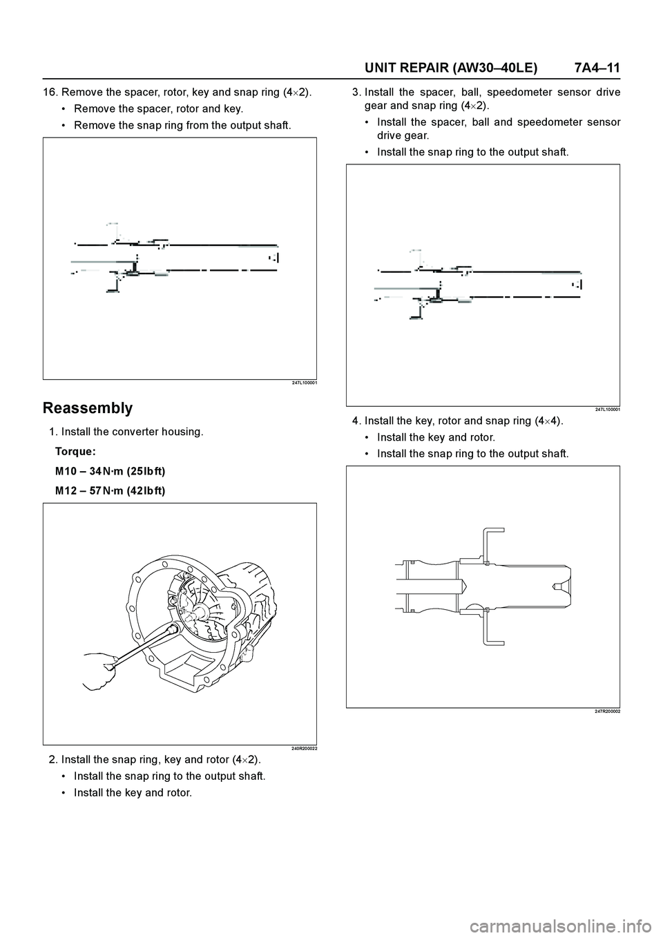
16. Remove the spacer, rotor, key and snap ring (4�2).
Remove the spacer, rotor and key.
Remove the snap ring from the output shaft.
2 47L10 000 1
Reassembly
1. Install the converter housing.
To r q u e :
M10 – 34 N·m (25 lb ft)
M12 – 57 N·m (42 lb ft)
2 40R20 002 2
2. Install the snap ring, key and rotor (4�2).
Install the snap ring to the output shaft.
Install the key and rotor.3. Install the spacer, ball, speedometer sensor drive
gear and snap ring (4�2).
Install the spacer, ball and speedometer sensor
drive gear.
Install the snap ring to the output shaft.
24 7L10 0001
4. Install the key, rotor and snap ring (4�4).
Install the key and rotor.
Install the snap ring to the output shaft.
2 47R20 0002
 (V6 3.5L) 7A2-71
DTC P1790 (FLASHING CODE 61) Transmission Control Module ROM
Checksum Error
Step Action Value(s) YES NO
1
Was the Powertrain ON-Bo")
 (V6 3.5L) 7A2-73
DTC P1791 (FLASHING CODE 62) Transmission Control Module RAM Error
Step Action Value(s) YES NO
1
Was the Powertrain On-Board Diagnos")
 7A4–7
Major Components (2)
Major Componets (2) and Associated Parts
RT W37 A LF00 0801
E nd O FCallo ut
Legend
(1) Converter housing
(2) Oil pan
(3) Oil strainer assembly
(")

8. Remove the accumulator piston (B–2).
9. Remove the accumulator piston (C–2).
Remove accumulator pistons and springs from
transmission case.
24 0RY 0 001 0
10")