Page 629 of 4264

CLUTCH 7C-27
201R300011
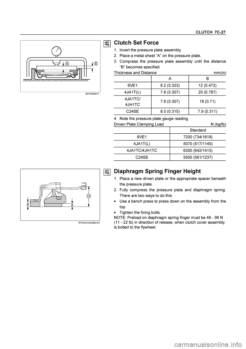
Clutch Set Force
1. Invert the pressure plate assembly.
2. Place a metal sheet “A” on the pressure plate.
3. Compress the pressure plate assembly until the distance
“B” becomes specified.
Thickness and Distance mm(in
)
A B
6VE1 8.2 (0.323) 12 (0.472)
4JA1T(L) 7.8 (0.307) 20 (0.787)
4JA1TC/
4JH1TC 7.8 (0.307) 18 (0.71)
C24SE 8.0 (0.315) 7.9 (0.311)
4. Note the pressure plate gauge reading.
Driven Plate Clamping Load N (kg/Ib)
Standard
6VE1 7200 (734/1618)
4JA1T(L) 5070 (517/1140)
4JA1TC/4JH1TC 6300 (642/1415)
C24SE 5500 (561/1237)
RTW37CSH000101
Diaphragm Spring Finger Height
1. Place a new driven plate or the appropriate spacer beneath
the pressure plate.
2. Fully compress the pressure plate and diaphragm spring.
There are two ways to do this.
�
Use a bench press to press down on the assembly from the
top.
� Tighten the fixing bolts.
NOTE: Preload on diaphragm spring finger must be 49 - 98 N
(11 - 22 lb) in direction of release, when clutch cover assembly
is bolted to the flywheel.
Page 633 of 4264

CLUTCH 7C-31
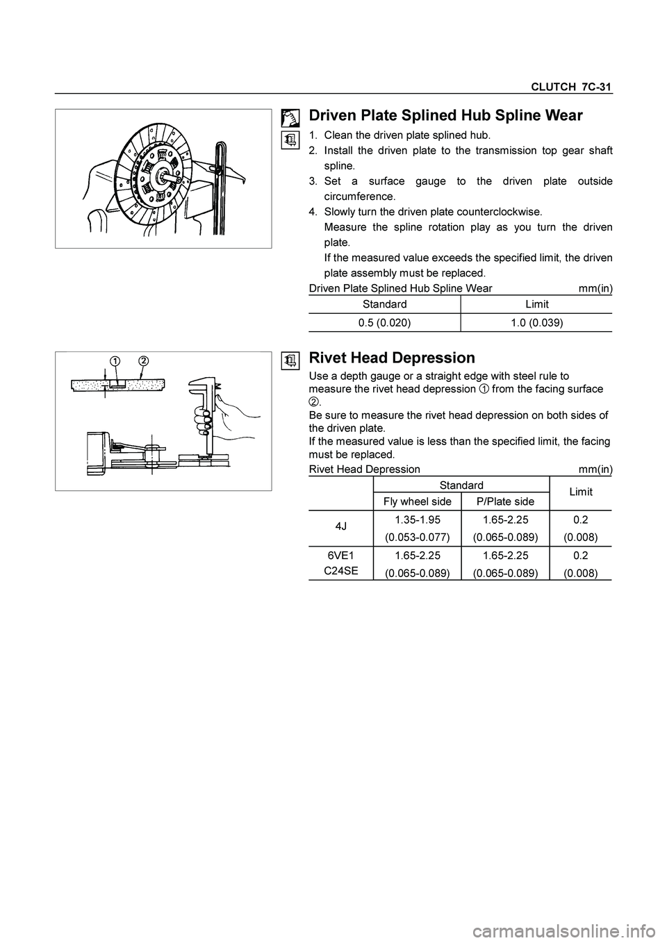
Driven Plate Splined Hub Spline Wear
1. Clean the driven plate splined hub.
2. Install the driven plate to the transmission top gear shaf
t
spline.
3. Set a surface gauge to the driven plate outside
circumference.
4. Slowly turn the driven plate counterclockwise.
Measure the spline rotation play as you turn the driven
plate.
If the measured value exceeds the specified limit, the driven
plate assembly must be replaced.
Driven Plate Splined Hub Spline Wear mm(in)
Standard Limit
0.5 (0.020) 1.0 (0.039)
Rivet Head Depression
Use a depth gauge or a straight edge with steel rule to
measure the rivet head depression
1 from the facing surface
2.
Be sure to measure the rivet head depression on both sides of
the driven plate.
If the measured value is less than the specified limit, the facing
must be replaced.
Rivet Head Depression mm(in)
Standard
Fly wheel side P/Plate side Limit
4J 1.35-1.95
(0.053-0.077) 1.65-2.25
(0.065-0.089) 0.2
(0.008)
6VE1
C24SE 1.65-2.25
(0.065-0.089) 1.65-2.25
(0.065-0.089) 0.2
(0.008)
Page 648 of 4264
7C-46 CLUTCH
Checkpoint Trouble Cause Countermeasure
Crankshaft pilot bearingReplace the pilot bearingTop gear shaft wobble is
causing pilot bearing wear
Repair or replace the flywheelFlywheel unevenly worn
NG NG OK
OKFlywheel Continued from the previous page
Page 650 of 4264
7C-48 CLUTCH
Checkpoint Trouble Cause Countermeasure
Replace the driven plate
assemblyWarpage and/or uneven wear
Replace the driven plate
assemblyLoose facing rivets
NG NG OKDriven plate Continued from the previous page
FlywheelRepair or replace the flywheelFlywheel uneven wear NG OK
Page 670 of 4264

8A-12 ELECTRICAL-BODY AND CHASSIS
ABBREVIATIONS
Abbreviation Meaning of abbreviation Abbreviation Meaning of abbreviation
A Ampere (S) LH Left hand
ABS Anti-lock brake system LWB Long wheel base
ASM Assembly MPI Multipart fuel injection
AC Alternating current M/T Manual transmission
A/C Air conditioner QOS Quick On Start system
ACC Accessories RH Right hand
CARB Carburetor RR Rear
C/B Circuit breaker RWAL Rear wheel anti-lock brake system
CSD Cold start device SRS Supplemental restraint system
DIS Direct ignition system ST Start
EBCM Electronic brake control module STD Standard
ECGI Electronic control gasoline injection SW Switch
ECM Engine control module SWB Short wheel base
ECU Electronic control unit TCM Transmission control module
EFE Early fuel evaporation V Volt
4�2 Two-wheel drive VSV Vacuum switching valve
4�4 Four-wheel drive W Watt (S)
FL Fusible link WOT Wide open throttle
FRT Front W/ With
H/L Headlight W/O Without
IC Integrated circuit
IG Ignition
kW Kilowatt
Page 787 of 4264

ELECTRICAL-BODY AND CHASSIS 8A-129
Installation
Follow the removal procedure in the reverse order to install the
headlight.
Pay close attention to the important points mentioned in the
following paragraphs.
Connector
Be absolutely sure that the headlight connector is securely
connected.
This will prevent a contact and an open circuit.
This illustration is based on RHD model
LIGHTING SWITCH
Removal
1. Disconnect the battery ground cable.
2. Remove the steering wheel
1.
Refer to the “STEERING” Section of this manual.
3. Remove the Instrument panel lower cover
2.
4. Remove the steering column cover
3.
This illustration is based on RHD model
5. Disconnect the connector.
6. Remove the lighting switch from the steering shaft.
Installation
Follow the removal procedure in the reverse order to install the
lighting switch.
Pay close attention to the important points mentioned in the
following paragraphs.
Connector
Be absolutely sure that the lighting switch connector is securely
connected.
This will prevent a poor contact and an open circuit.
Wire Harness
Do not pinch the wire harnesses between the cluster and the
meter hood during the cluster installation procedure.
Wire damage will result.
Page 789 of 4264

ELECTRICAL-BODY AND CHASSIS 8A-131
LICENSE PLATE LIGHT
Removal
1. Remove the lens cover 1 and the connector 2.
2. Pull the bulb
3 to remove it.
Installation
Follow the removal procedure in the reverse order to install the
license plate light.
Pay close attention to the important points mentioned in the
following paragraphs.
Bulb
Be absolutely sure that the license plate light bulb is correctly
installed.
This will prevent a poor contact and open circuit.
HEADLIGHT BEAM SWITCH
(COMBINATION SWITCH)
Removal
1. Disconnect the battery ground cable.
2. Remove the screws on the lower part of the steering wheel.
3. Remove the horn pad.
4. Remove the wiring connector.
5. Remove the steering wheel fixing nuts.
6. Remove the steering wheel.
Refer to the "STEERING" Section of this manual.
7. Remove the Instrument panel lower cover.
8. Remove the steering column cover.
9. Disconnect the connector.
10. Remove the headlight beam switch (lever) from the steering
shaft (combination switch).
Installation
Follow the removal procedure in the reverse order to install the
headlight beam switch (lever).
Pay close attention to the important points mentioned in the
following paragraphs.
Connector
Be absolutely sure that the headlight beam switch connector is
securely connected.
This will prevent a poor contact and an open circuit.
Page 811 of 4264
ELECTRICAL-BODY AND CHASSIS 8A-153
HEADLIGHT LEVELING SWITCH
Incorrect beam angle due to load change can be corrected.
A four position switch, 0-3, can alter the beam angle through
1.7 degrees on the long wheel base model and 2.17 degrees
on the short wheel base model.
825R300049
Inspection
Check to see if there is any continuity between the terminals of
the leveling switch.
Replace the switch when the result of inspection is found
abnormal.
Removal
Preparation:
Disconnect the battery ground cable.
1. Ventilation grille
2. Harness connector
3. Headlight leveling switch
To remove the switch, push the lock from the back side of
the cluster assembly.
Installation
To install, follow the removal steps in the reverse noting the
following point.
1. Push in the switch with your fingers until it locks securely.