Page 595 of 4264
CAB 10-87
FRONT WHEEL EXTENTION
REMOVAL AND INSTALLATION
Removal Steps
1. Screw
� 2. Front wheel extension
Installation Steps
2. Front wheel extension
1. Screw
Important Operation - Removal
2. Front Wheel Extension � pull out the 5 clip positions
Page 596 of 4264
10-88 CAB
REAR WHEEL EXTENTION
REMOVAL AND INSTALLATION
RTW4A0MF000501
Removal Steps
1. Screw
� 2. Rear wheel extension
Installation Steps
2. Rear wheel extension
1. Screw
Important Operation - Removal
2. Rear Wheel Extension � Pull out the 6 clip positions (Extend cab)
� Pull out the 5 clip positions (Crew cab)
Page 606 of 4264
7C-4 CLUTCH
The clutch assembly consists of the pressure plate, the clutch cover, the diaphragm spring pivot pin and the driven
plate assembly.
The clutch pedal is connected to the release bearing through the shift fork.
The driven plate assembly is installed between the flywheel and the pressure plate.
For 4J series engine and HEC engine models, the push-type clutch is used.
Diaphragm spring pressure holds the driven plate against flywheel and the pressure plate to provide the friction
necessary to engage the clutch.
Depressing the clutch pedal moves the shift fork against the release bearing.
The release bearing forces the diaphragm to overcome the force of the diaphragm spring and separate the driven
plate from the flywheel and pressure plate to disengage the clutch.
For 6VE1 engine model, the pull-type clutch is used. The pull-type clutch is disengaged by pulling the release lever
(release bearing) to disengage the pressure plate.
Page 623 of 4264
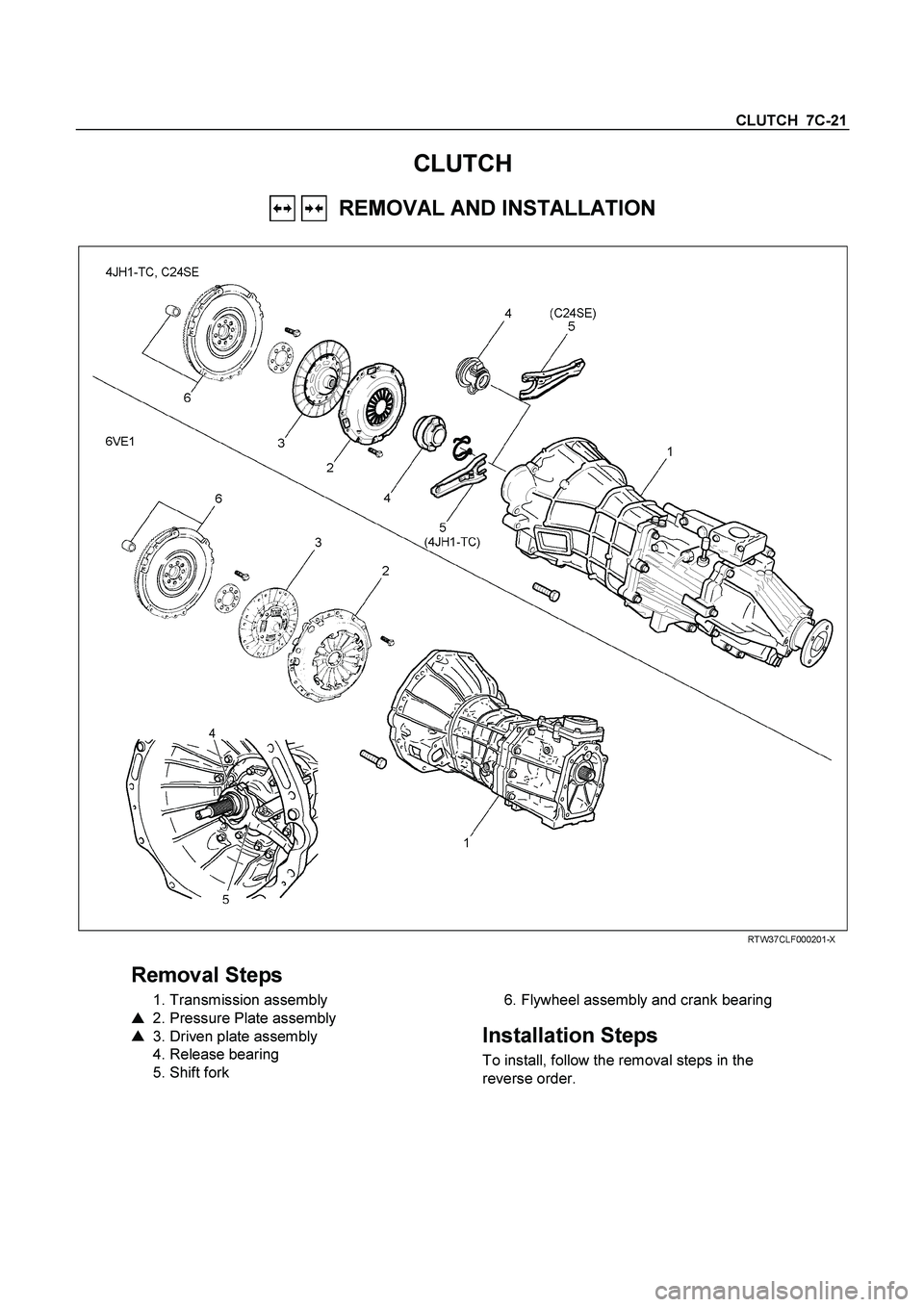
CLUTCH 7C-21
CLUTCH
REMOVAL AND INSTALLATION
RTW37CLF000201-X
Removal Steps
1. Transmission assembly
�
2. Pressure Plate assembly
�
3. Driven plate assembly
4. Release bearing
5. Shift fork
6. Flywheel assembly and crank bearing
Installation Steps
To install, follow the removal steps in the
reverse order.
Page 624 of 4264
7C-22 CLUTCH
Important Operations - Removal
1. Transmission Assembly
Refer to “MANUAL TRANSMISSION” of section 7B and 7B1
for “REMOVAL AND INSTALLATION” procedure.
2. Clutch Pressure Plate Assembly
3. Driven Plate Assembly
(1) Use the clutch pilot aligner
1 to prevent the driven plate
assembly
2 from falling free.
Clutch Pilot Aligner : 5-85253-001-0
(2) Loosen the clutch cover bolts in the numerical order shown
in the illustration.
(3) Remove the pressure plate assembly
3 from the flywheel.
(4) Remove the driven plate from the flywheel.
201RS017
220RW088-X
4. Release Bearing (6VE1)
5. Shift Fork (6VE1)
(1) Remove the release bearing (1) from the transmission
case.
(2) Remove the shift fork snap pin (2).
(3) Remove the shift fork pin and shift fork (3) from the fulcrum
bridge.
6VE1 4JH1-TC, C24SE
Page 625 of 4264
CLUTCH 7C-23
015RW053
6. Flywheel Assembly and Crank Bearing (6VE1)
(1) Remove flywheel assembly and crankshaft bearing. Do no
t
remove except for replacement.
(2) Use the remover 5-8840-2000-0 (J-5822) and sliding
hammer 5-8840-0019-0 (J-23907) to remove the crankshaf
t
bearing
Important Operations - Installation
Follow the removal procedure in reverse order to perform the
installation procedure.
Pay careful attention to the important points during the
installation procedure.
015RW054
6. Flywheel Assembly and Crank Bearing (6VE1)
(1) Install flywheel assembly and crankshaft bearing. Use the
installer 5-8840-0125-0 (J-26516-A) and driver handle 5-
8840-0007-0 (J-8092) to install the crankshaft bearing then
clean and lubricate with grease.
015RS047
(2) Install new flywheel fixing bolts in the order illustrated and
tighten them to the specified torque.
N�
m (kg�
m/lb ft)
6VE1 54 (5.5/40)
NOTE: Do not reuse the bolt and do not apply oil or thread lock
to the bolt.
Page 626 of 4264
7C-24 CLUTCH
201RW019
5. Shift Fork (6VE1)
4. Release Bearing (6VE1)
(1)
Apply molybdenum disulfide type grease to the pin hole
inner circumferences and thrust surfaces.
(2)
Attach the shift fork to the front cover and insert the pin
from below of the front cover.
(3) Install the washer and snap pin.
201RW012
(4) Apply molybdenum disulfide type grease to the areas
shown in illustration.
201RW020
(5) Install the release bearing in the proper direction.
NOTE: Ensure release bearing is properly positioned during
installation, as shown in illustration.
3. Driven plate Assembly
2. Clutch Pressure Plate Assembly
(1) Clean the flywheel surface.
(2) Clean the facing surface.
(3) Use the clutch pilot aligner
1 to install the driven plate
assembly
2 to the flywheel
3.
Clutch Pilot Aligner : 5-8525-3001-0
Page 627 of 4264
CLUTCH 7C-25
(4) Clean the pressure plate surfaces.
(5) Align the pressure plate assembly
4 with the flywheel
knock pin
5.
(6) Install the pressure plate assembly to the flywheel.
(7) Tighten the clutch cover bolts a little at a time in the
numerical order shown in the illustration.
Clutch Cover Bolt Torque N�
m (kgf�
m/lb�
ft)
18 �
3 (1.8 �
0.3 / 13.0 �
2.2)
201RS017
(8) Remove the clutch pilot aligner.
Note:
Do not strike the clutch pilot aligner with a hammer to
remove it.
4JH1-TC, C24SE
6VE1


(1) Remove flywheel assembly and crankshaft bearing. Do no
t
remove except for replacement.
(2) Use the remover 5-8840-2000-0")

4. Release Bearing (6VE1)
(1)
Apply molybdenum disulfide type grease to the pin hole
inner circumferences and thrust surfaces.
(2)
Attach the shift")
 Clean the pressure plate surfaces.
(5) Align the pressure plate assembly
4 with the flywheel
knock pin
5.
(6) Install the pressure plate assembly to the flywheel.
(")