Page 536 of 4264
10-28 CAB
INSTRUMENT PANEL
REMOVAL
This illustration is based on RHD model
RTW4A0LF001001
Disassembly Steps
� 1. Front console assembly
� 2. Glove box
� 3. Instrument panel driver lower cover
assembly
� 4. Driver knee bolster assembly
� 5. Driver air bag
� 6. Steering wheel/ steering cowl
� 7. Meter cluster assembly
8. Dash side trim cover
9. Front pillar trim cover
10. Front cover
11. Side cover
� 12. Instrument panel & Cross beam
assembly
�
13. Ashtray case
� 14. Center cluster assembly
� 15. Control lever assembly
16. Storage box assembly
� 17. Ashtray bracket
18. Meter assembly
19. Passenger lower bracket
20. Glove box cover
� 21. Passenger air bag (if so equipped)
� 22. Side ventilation grille
� 23. Vent duct assembly/Defroster nozzle
assembly
24. Instrument harness assembly
� 25. Instrument panel
� 26. Cross beam
Page 537 of 4264
CAB 10-29
Important Operations
1. Front Console Assembly
�
Refer to Floor Consol in this section.
2. Glove Box
�
Remove 2 fixing screws and pulling the handle.
3. Instrument Panel Driver Lower Cover Assembly
1) Remove the engine hood opener 2 fixing screws.
2) Remove the lower cover one fixing screw.
3) Pull out the cover (Stick type parking brake only).
4) Pull out the lower cover assembly.
4. Driver Knee Bolster Assembly
�
Remove 4 fixing bolts.
Caution:
For precaution on installation or removal of SRS-air bag
system, refer to section 9 “Supplemental Restraint System
(SRS) - AIR BAG”
5. Driver Air Bag
6. Steering Wheel/Steering Cowl
�
Refer to Section 3B “STEERING COLUMN” for steering
lock assembly removal steps.
7. Meter Cluster Assembly
�
Pull out the 4 clip positions.
Page 540 of 4264
10-32 CAB
INSTALLATION
This illustration is based on RHD model
RTW4A0LF001101
Installation Steps
1. Cross beam
2. Instrument panel
3. Instrument harness assembly
4. Vent duct assembly/Defroster nozzle
assembly
5. Side ventilation grille
6. Passenger air bag
7. Glove box cover
8. Passenger lower bracket
9. Meter assembly
10. Ashtray bracket
11. Storage box assembly
12. Control lever assembly
13. Center cluster assembly
14. Ashtray case
� 15. Instrument panel & Cross beam
assembly
16. Side cover
17. Front cover
18. Front pillar trim cover
19. Dash side trim cover
20. Meter cluster assembly
� 21. Steering wheel/Steering cowl
22. Driver air bag
23. Driver knee bolster assembly
24. Instrument panel driver lower cover assembly
25. Glove box
26. Front console assembly
Page 541 of 4264
CAB 10-33
Important Operations
15. Instrument Panel & Crass Beam Assembly
1) Tighten the 4 bolts fixing the cross beam and body panel
to the specified torque.
Torque N�
m (kgf�
m/lb�
ft)
19 (1.9/14)
2) A Bolt: Steering Column to Cross Beam
Torque N�
m (kgf�
m/lb�
ft)
20 (2.0/14)
B Bolt: Pedal Bracket to Cross Beam
Torque N�
m (kgf�
m/lb�
ft)
15 (1.5/11)
3) C Bolt: Parking Brake Bracket to Cross Beam
Torque N�m (kgf�m/lb�ft)
15 (1.5/11)
21. Steering Wheel/Steering Cowl
� Tighten the steering wheel fixing nut to the specified
truque.
Torque N�
m (kgf�
m/lb�
ft)
35 (3.6/26)
Page 563 of 4264
CAB 10-55
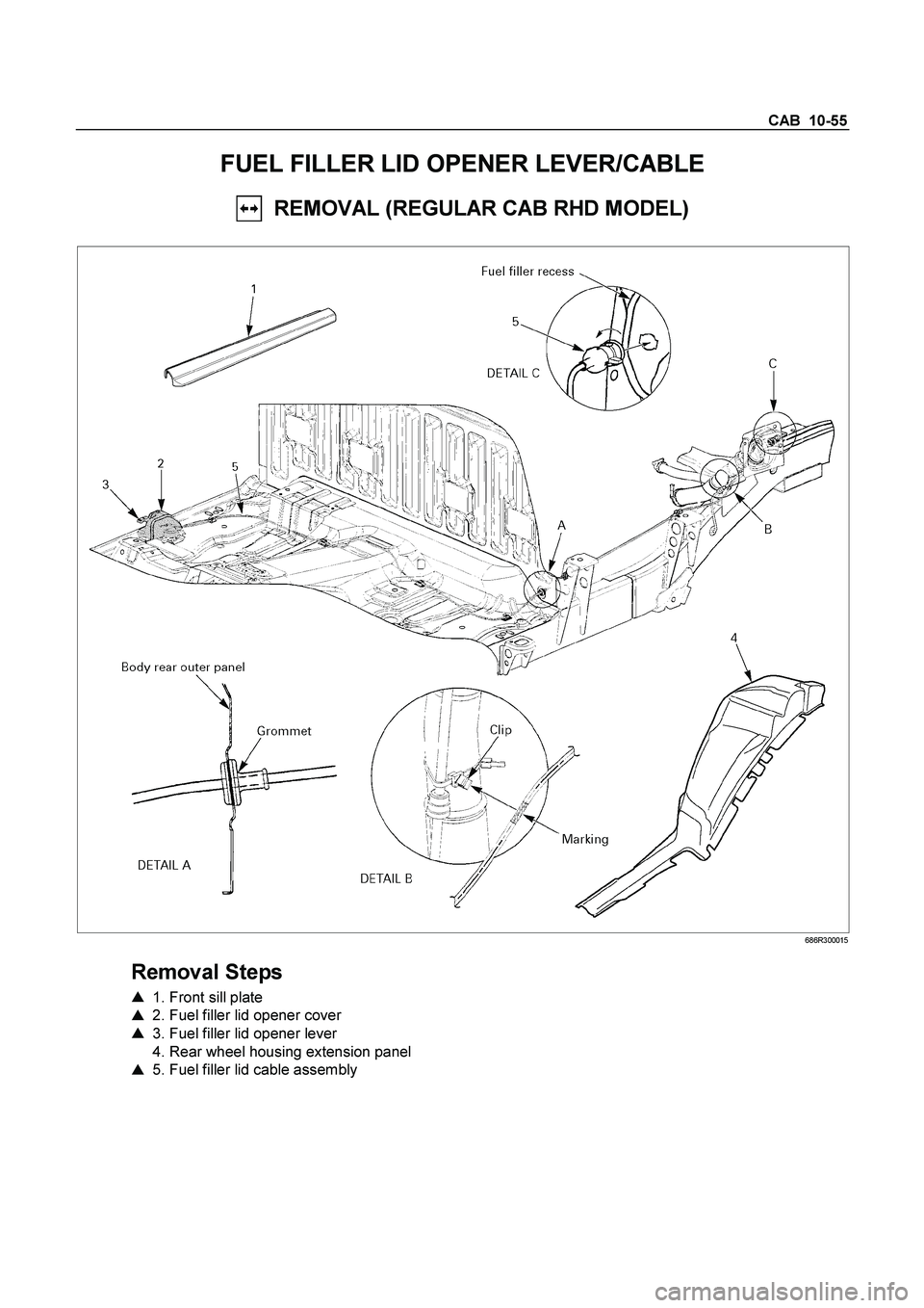
FUEL FILLER LID OPENER LEVER/CABLE
REMOVAL (REGULAR CAB RHD MODEL)
686R300015
Removal Steps
� 1. Front sill plate
� 2. Fuel filler lid opener cover
� 3. Fuel filler lid opener lever
4. Rear wheel housing extension panel
� 5. Fuel filler lid cable assembly
Page 564 of 4264
10-56 CAB
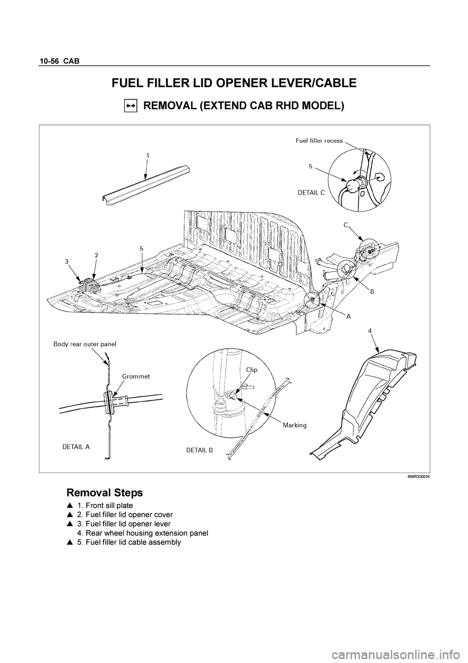
FUEL FILLER LID OPENER LEVER/CABLE
REMOVAL (EXTEND CAB RHD MODEL)
686R300016
Removal Steps
� 1. Front sill plate
� 2. Fuel filler lid opener cover
� 3. Fuel filler lid opener lever
4. Rear wheel housing extension panel
� 5. Fuel filler lid cable assembly
Page 565 of 4264
CAB 10-57
FUEL FILLER LID OPENER LEVER/CABLE
REMOVAL (REGULAR CAB LHD MODEL)
RTW4A0LF000101
Removal Steps
� 1. Front sill plate
� 2. Fuel filler lid opener cover
� 3. Fuel filler lid opener lever
4. Rear wheel housing extension panel
� 5. Fuel filler lid cable assembly
Page 566 of 4264
10-58 CAB
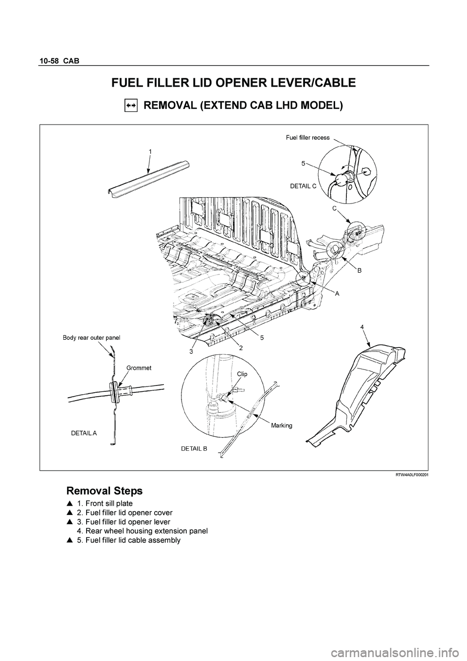
FUEL FILLER LID OPENER LEVER/CABLE
REMOVAL (EXTEND CAB LHD MODEL)
RTW4A0LF000201
Removal Steps
� 1. Front sill plate
� 2. Fuel filler lid opener cover
� 3. Fuel filler lid opener lever
4. Rear wheel housing extension panel
� 5. Fuel filler lid cable assembly