Page 402 of 4264
5A-86 BRAKE CONTROL SYSTEM
DTC C0282 (Flash Code 82) 4 Wheel Drive State Input Signal Failure
RTW35AMF000301
Step Action
Value(s) Yes No
1 Was the “Basic Diagnostic Flow Chart” performed?
- Go to Step 2 Go to Basic
Diagnostic
Flow Chart
2 1. Check for a poor connection at EHCU and 2-4WD
control unit.
2. If a problem is found, repair as necessary.
Was a problem found?
- Verify repair Go to Step 3
3 1. Ignition “OFF,” disconnect the EHCU and 2-4WD
control unit.
2. Check the circuit between EHCU and 2-4WD
control unit. (Circuit for an open, short to ground, or
short to voltage.)
3. If a problem is found, repair as necessary.
Was a problem found?
- Verify repair Go to Step 4
4 1. Check the 2-4WD Control system.
2. If a problem is found, repair as necessary.
Was a problem found?
- Verify repair Go to Step 5
Page 407 of 4264

ANTI-LOCK BRAKE SYSTEM 5B-1
SECTION 5B
BRAKES
ANTI-LOCK BRAKE SYSTEM
TABLE OF CONTENTS
PAGE
Service Precaution ...................................................................................................................... 5B – 2
Torque Specifications ................................................................................................................ 5B – 3
Electronic Hydraulic Control Unit ........................................................................................... 5B – 7
Electronic Hydraulic Control Unit and Associated Parts ............................................ 5B – 7
Removal .................................................................................................................................... 5B – 7
Installation ................................................................................................................................ 5B – 7
Front Wheel Speed Sensor ....................................................................................................... 5B – 8
Front Wheel Speed Sensor and Associated Parts ........................................................ 5B – 8
Removal .................................................................................................................................... 5B – 9
Inspection and Repair ........................................................................................................... 5B – 9
Installation ................................................................................................................................ 5B – 10
Rear Wheel Speed Sensor ........................................................................................................ 5B – 11
Rear Wheel Sensor and Associated Parts ....................................................................... 5B – 11
Removal .................................................................................................................................... 5B – 11
Inspection and Repair ........................................................................................................... 5B – 11
Installation ................................................................................................................................ 5B – 12
Front Speed Sensor Rotor ........................................................................................................ 5B – 13
Front Sensor Rotor and Associated Parts ....................................................................... 5B – 13
Removal .................................................................................................................................... 5B – 13
Inspection and Repair ........................................................................................................... 5B – 14
Installation ................................................................................................................................ 5B – 14
Rear Speed Sensor Rotor .......................................................................................................... 5B – 16
Rear Sensor Rotor and Associated Parts ........................................................................ 5B – 16
Removal .................................................................................................................................... 5B – 16
Inspection and Repair ........................................................................................................... 5B – 17
Installation ................................................................................................................................ 5B – 17
G-Sensor ........................................................................................................................................ 5B – 19
G-Sensor and Associated Parts ......................................................................................... 5B – 19
Page 413 of 4264
ANTI-LOCK BRAKE SYSTEM 5B-7
Electronic Hydraulic Control Unit
Electronic Hydraulic Control Unit and Associated Parts
RHD model LHD model
350R300001-X
Legend
1.
Flare Nut from master cylinder front
2.
Flare Nut to front right wheel cylinder
3. Flare Nut to front left wheel cylinder
4.
Flare Nut to rear wheel cylinder
5.
Electronic Hydraulic Control Unit (EHCU)
6.
Flare Nut from master cylinder rear
7.
Bolt
8.
Front
Removal
1. Disconnect the harness connector.
2. Loosen five flare nuts and remove brake pipes.
�
After disconnecting brake pipe, cap or tape the
openings of the brake pipe to prevent the entry o
f
foreign matter.
3. Remove three bracket fixing bolts.
Installation
1. Install EHCU and tighten the bolt to the specified
torque.
Torque : 8 N�
m (0.8 kg�
m /69 lb in)
2. Tighten the flare nuts to the specified torque.
Torque : 16 N�
m (1.6 kg�
m /12 lb ft)
3. Connect the harness connector.
Page 414 of 4264
5B -8 ANTI-LOCK BRAKE SYSTEM
Front Wheel Speed Sensor
Front Wheel Speed Sensor and Associated Parts
4�
�� �2
350R300005
Page 417 of 4264
ANTI-LOCK BRAKE SYSTEM 5B-11
Rear Wheel Speed Sensor
Rear Wheel Sensor and Associated Parts
420R300008
Legend
1.
Rear Speed Sensor Assembly
2.
Bolt : cable to frame
3.
Connector
4. Bolt : sensor to rear axle
5.
Speed Sensor
6. Bolt : cable to axle
7.
Bolt : sensor to rear axle
8.
Speed Sensor
Removal
1. Disconnect the harness connector (3).
2. Remove the cable fixing bolt (2)(6).
3. Disconnect the cable fixing clips (arrow marked).
4. Remove the speed sensor fixing bolts (4)(7) and
speed sensor (5)(8).
Inspection and Repair
1. Check speed sensor head for presence of foreign
materials; remove any dirt, etc.
2. Check the head for damage, and replace speed
sensor if necessary.
Page 419 of 4264
ANTI-LOCK BRAKE SYSTEM 5B-13
Front Speed Sensor Rotor
Front Sensor Rotor and Associated Parts
411R300010
Legend
1.
Sensor Rotor
2.
Hub and Disc
3.
Disc Rotor fixing Bolt
4. Hub and Disc Assembly
Removal
1. Remove the hub and disc assembly (4). (Refer to
the section Front wheel Drive).
2. Remove two disc rotor fixing bolts (3) on a diagonal.
3. Drive out the sensor rotor using a metal bar and
hammer through the two bolt holes.
�
Discard the used sensor rotor.
4. Install disc rotot fixing bolts and tighten them to the
specified torque.
Torque : 103 N�
m (10.5 kg�
m /76 lb ft)
Page 421 of 4264
ANTI-LOCK BRAKE SYSTEM 5B-15
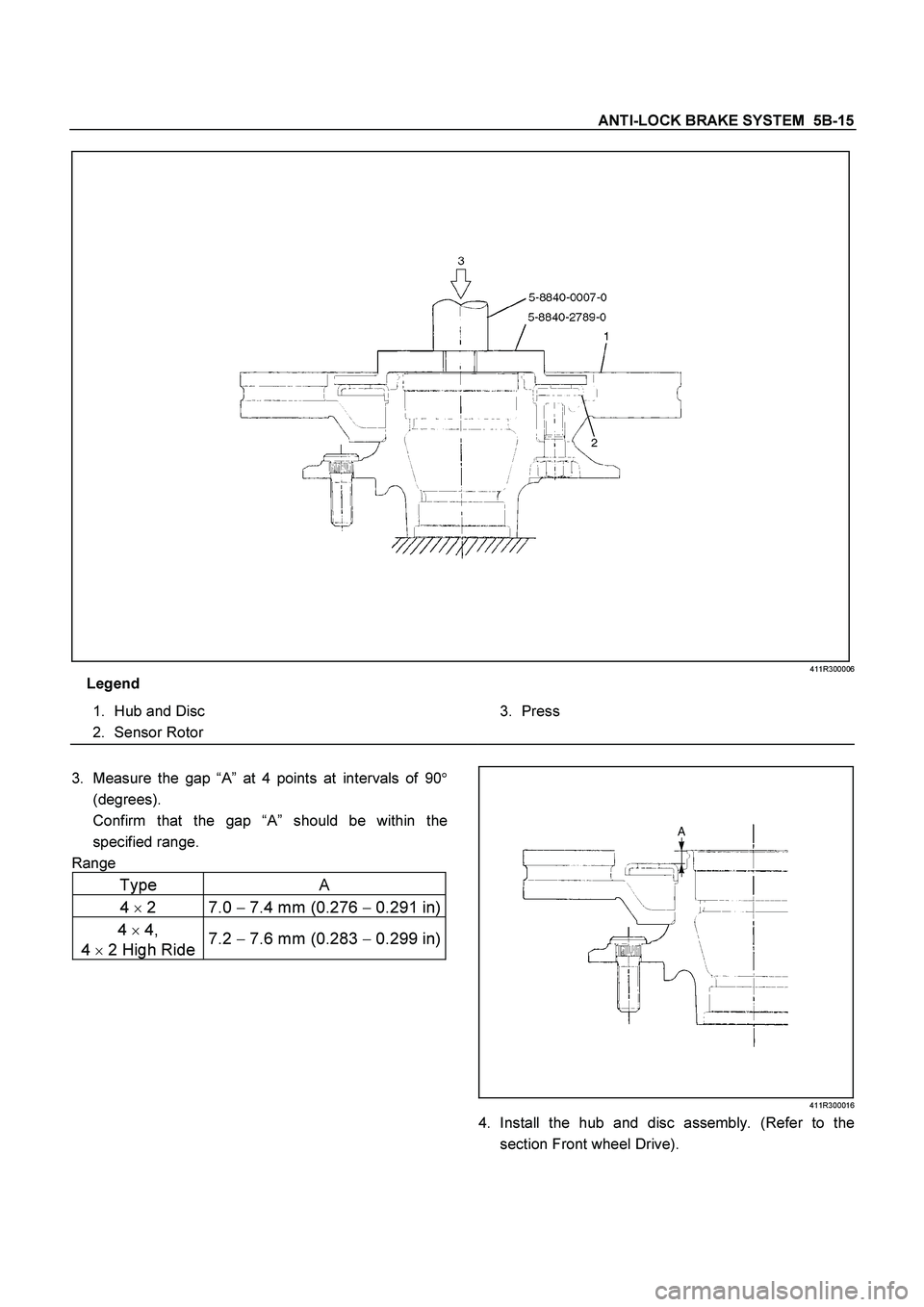
411R300006
Legend
1.
Hub and Disc
2.
Sensor Rotor
3.
Press
3.
Measure the gap “A” at 4 points at intervals of 90�
(degrees).
Confirm that the gap “A” should be within the
specified range.
Range
Type A
4
�
2 7.0 �
7.4 mm (0.276 �
0.291 in)
4
�
4,
4
�
2 High Ride 7.2
� 7.6 mm (0.283
� 0.299 in)
411R300016
4. Install the hub and disc assembly. (Refer to the
section Front wheel Drive).
Page 429 of 4264
BRAKES 5C-3
REAR WHEEL CYLINDER
LOAD SENSING PROPORTIONING VALVE (LSPV)
RTW35CMF000101
 4 Wheel Drive State Input Signal Failure
RTW35AMF000301
Step Action
Value(s) Yes No
1 Was the “Basic Diagnostic Flow Chart” p")


RTW35CMF000101")