Page 829 of 4264
ELECTRICAL-BODY AND CHASSIS 8A-171
HORN
1. Both sides of horn do not sound
Checkpoint Trouble Cause Countermeasure
Repair the grounding point
Poor ground contact
NG
Horn relay
Grounding point
Reinstall or replace fuse No.
EB-15 (10A)
Fuse No EB-15 (10A, Relay
and fuse box)
Poor fuse contact or blown
fuse
NG
OK OK
Reinstall or replace the horn
relay
Poor relay contact or faulty
horn relay
NG
Voltage between connector
3
X-3 - ground or 1 X-3
- ground (Should be battery
voltage present) OK
Repair open circuit or
reconnect the connector
Open circuit or poor connector
contact between fuse No. EB-
15 (10A) and horn relay
NG
Remove steering pad and
steering wheel
OK
Horn switch continuity
OK
Repair or replace the horn
switch
Poor switch point contact or
faulty switch
NG
Continuity between
4
X-3 - 10 B-60
2
X-3 - 1 C-20 (1 C-21) OK
Repair open circuit or
connector contact
Open circuit or poor connector
contact
NG
Page 834 of 4264
8A-176 ELECTRICAL-BODY AND CHASSIS
This illustration is based on RHD model
TURN SIGNAL SWITCH
Removal
1. Disconnect the battery ground cable.
2. Remove the steering wheel
1.
Refer to the “STEERING” Section of this Manual.
3. Remove the instruments panel lower cover
2.
4. Remove the steering column cover
3.
This illustration is based on RHD model
5. Disconnect the connector.
6. Remove the turn signal switch from the steering shaft.
Installation
Follow the removal procedure in the reverse order to install the
turn signal switch (lever).
Pay close attention to the important points mentioned in the
following paragraphs.
Connector
Be absolutely sure that the turn signal switch connector is
securely connected.
This will prevent a poor contact and at an open circuit.
Page 837 of 4264
ELECTRICAL-BODY AND CHASSIS 8A-179
HORN SWITCH
Removal
1. Disconnect the battery ground cable.
2. Disable the SRS (Refer to “Disabling the SRS”in this
section).
3. Check the both side hole of the steering cover.
4. Check the position of the pins in a hole. Push the pin in the
direction of an arrow.
5. Push the four pins at �5�6 mm bar.
6. Cancel the lock four pins.
7. Disconnect the SRS air bag connector and horn lead
connector located behind the air bag assembly and remove
the air bag assembly.
Installation
1. Connect the SRS bag connector and horn lead connector.
2.
Align the each snap stud of driver air bag to the hole of
steering wheel.
Page 1128 of 4264

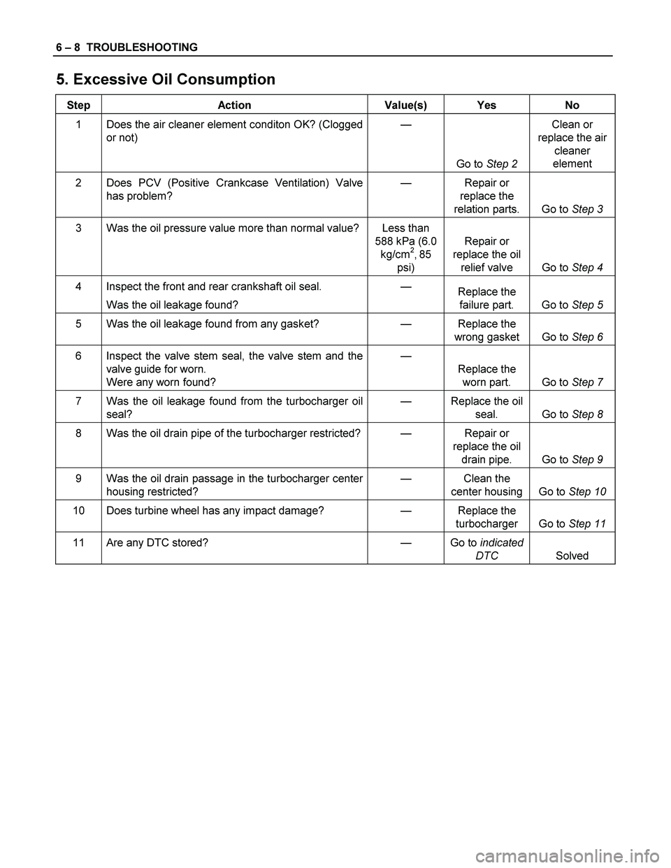
6 – 8 TROUBLESHOOTING
5. Excessive Oil Consumption
Step Action Value(s) Yes No
1 Does the air cleaner element conditon OK? (Clogged
or not) —
Go to Step 2 Clean or
replace the air
cleaner
element
2 Does PCV (Positive Crankcase Ventilation) Valve
has problem? — Repair or
replace the
relation parts. Go to Step 3
3 Was the oil pressure value more than normal value? Less than
588 kPa (6.0
kg/cm
2, 85
psi) Repair or
replace the oil
relief valve Go to Step 4
4 Inspect the front and rear crankshaft oil seal.
Was the oil leakage found? —
Replace the
failure part. Go to Step 5
5 Was the oil leakage found from any gasket? — Replace the
wrong gasket Go to Step 6
6 Inspect the valve stem seal, the valve stem and the
valve guide for worn.
Were any worn found? —
Replace the
worn part. Go to Step 7
7 Was the oil leakage found from the turbocharger oil
seal? — Replace the oil
seal. Go to Step 8
8 Was the oil drain pipe of the turbocharger restricted?— Repair or
replace the oil
drain pipe. Go to Step 9
9 Was the oil drain passage in the turbocharger center
housing restricted? — Clean the
center housing Go to Step 10
10 Does turbine wheel has any impact damage? — Replace the
turbocharger Go to Step 11
11 Are any DTC stored? — Go to indicated
DTC Solved
Page 1130 of 4264
6 – 10 TROUBLESHOOTING
8. Dark Exhaust Smoke
Step Action Value(s) Yes No
1 Was the air cleaner element normal condition? —
Go to Step 2 Clean or
replace the air
cleaner
element
2 Was the EGR valve sticking? — Replace the
EGR valve Go to Step 3
3 Was the injection nozzle pressure or the injection
spray pattern OK? —
Go to Step 4 Replace the
injection nozzle
4 Was the oil leakage found from the turbocharger oil
seal? — Replace the oil
seal Go to Step 5
5 Was the oil drain pipe of the turbocharger restricted?— Repair or
replace the oil
drain pipe Go to Step 6
6 Was restricted the oil drain passage in the
turbocharger center housing restricted? — Clean the
center housing Go to Step 7
7 Does turbine wheel has any impact damage? — Replace the
turbocharger Go to Step 8
8 Does PCV (Positive Crankcase Ventilation) Valve
has problem? — Repair or
replace the
relation parts Go to Step 9
9 Are any DTC stored? — Go to indicated
DTC Solved
Page 1133 of 4264

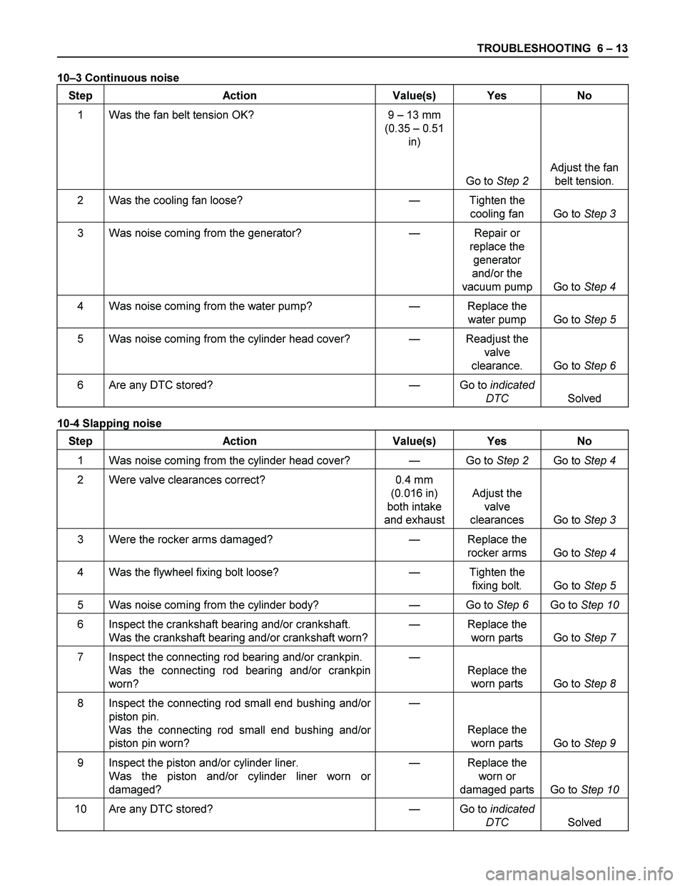
TROUBLESHOOTING 6 – 13
10–3 Continuous noise
Step Action Value(s) Yes No
1 Was the fan belt tension OK? 9 – 13 mm
(0.35 – 0.51
in)
Go to Step 2 Adjust the fan
belt tension.
2 Was the cooling fan loose? — Tighten the
cooling fan Go to Step 3
3 Was noise coming from the generator? — Repair or
replace the
generator
and/or the
vacuum pump Go to Step 4
4 Was noise coming from the water pump? — Replace the
water pump Go to Step 5
5 Was noise coming from the cylinder head cover? — Readjust the
valve
clearance. Go to Step 6
6 Are any DTC stored? — Go to indicated
DTC Solved
10-4 Slapping noise
Step Action Value(s) Yes No
1 Was noise coming from the cylinder head cover? — Go to Step 2 Go to Step 4
2 Were valve clearances correct? 0.4 mm
(0.016 in)
both intake
and exhaustAdjust the
valve
clearances Go to Step 3
3 Were the rocker arms damaged? — Replace the
rocker arms Go to Step 4
4 Was the flywheel fixing bolt loose? — Tighten the
fixing bolt. Go to Step 5
5 Was noise coming from the cylinder body? — Go to Step 6 Go to Step 10
6 Inspect the crankshaft bearing and/or crankshaft.
Was the crankshaft bearing and/or crankshaft worn?— Replace the
worn parts Go to Step 7
7 Inspect the connecting rod bearing and/or crankpin.
Was the connecting rod bearing and/or crankpin
worn? —
Replace the
worn parts Go to Step 8
8 Inspect the connecting rod small end bushing and/or
piston pin.
Was the connecting rod small end bushing and/or
piston pin worn? —
Replace the
worn parts Go to Step 9
9 Inspect the piston and/or cylinder liner.
Was the piston and/or cylinder liner worn or
damaged? — Replace the
worn or
damaged parts Go to Step 10
10 Are any DTC stored? — Go to indicated
DTC Solved
Page 1134 of 4264

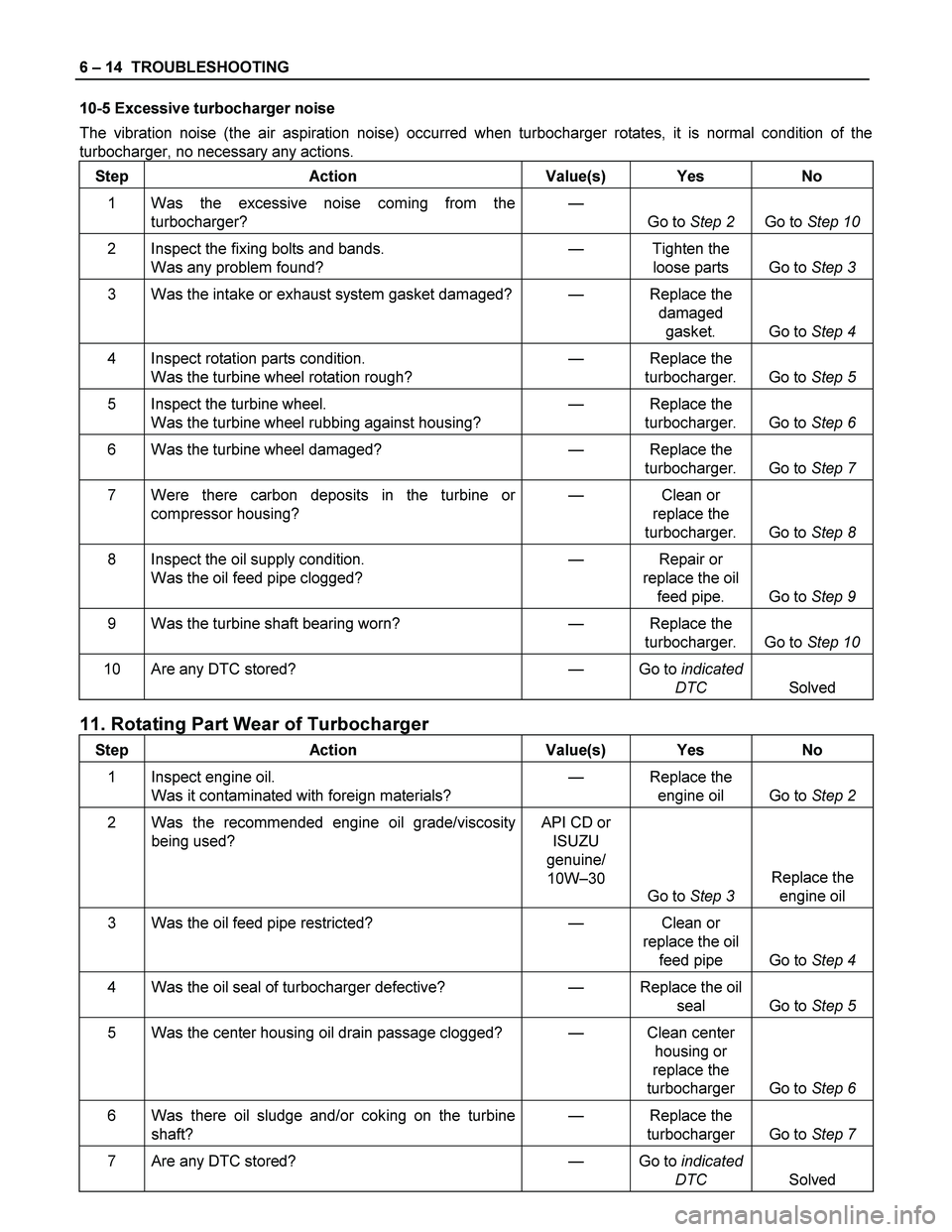
6 – 14 TROUBLESHOOTING
10-5 Excessive turbocharger noise
The vibration noise (the air aspiration noise) occurred when turbocharger rotates, it is normal condition of the
turbocharger, no necessary any actions.
Step Action Value(s) Yes No
1 Was the excessive noise coming from the
turbocharger? —
Go to Step 2 Go to Step 10
2 Inspect the fixing bolts and bands.
Was any problem found? — Tighten the
loose parts Go to Step 3
3 Was the intake or exhaust system gasket damaged?— Replace the
damaged
gasket. Go to Step 4
4 Inspect rotation parts condition.
Was the turbine wheel rotation rough? — Replace the
turbocharger. Go to Step 5
5 Inspect the turbine wheel.
Was the turbine wheel rubbing against housing? — Replace the
turbocharger. Go to Step 6
6 Was the turbine wheel damaged? — Replace the
turbocharger. Go to Step 7
7 Were there carbon deposits in the turbine or
compressor housing? — Clean or
replace the
turbocharger. Go to Step 8
8 Inspect the oil supply condition.
Was the oil feed pipe clogged? — Repair or
replace the oil
feed pipe. Go to Step 9
9 Was the turbine shaft bearing worn? — Replace the
turbocharger. Go to Step 10
10 Are any DTC stored? — Go to indicated
DTC Solved
11. Rotating Part Wear of Turbocharger
Step Action Value(s) Yes No
1 Inspect engine oil.
Was it contaminated with foreign materials? — Replace the
engine oil Go to Step 2
2 Was the recommended engine oil grade/viscosity
being used? API CD or
ISUZU
genuine/
10W–30
Go to Step 3 Replace the
engine oil
3 Was the oil feed pipe restricted? — Clean or
replace the oil
feed pipe Go to Step 4
4 Was the oil seal of turbocharger defective? — Replace the oil
seal Go to Step 5
5 Was the center housing oil drain passage clogged? — Clean center
housing or
replace the
turbocharger Go to Step 6
6 Was there oil sludge and/or coking on the turbine
shaft? — Replace the
turbocharger Go to Step 7
7 Are any DTC stored? — Go to indicated
DTC Solved
Page 1135 of 4264

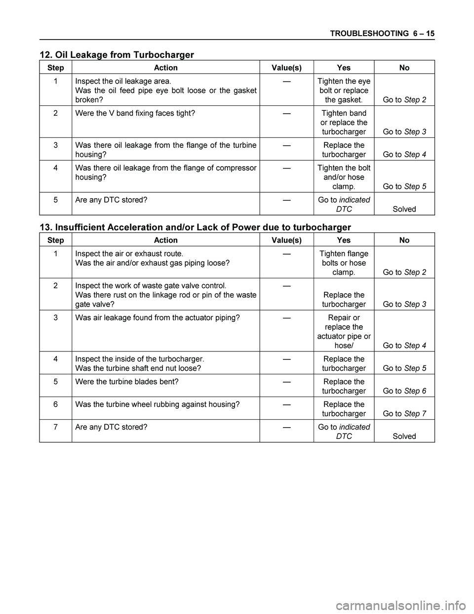
TROUBLESHOOTING 6 – 15
12. Oil Leakage from Turbocharger
Step Action Value(s) Yes No
1 Inspect the oil leakage area.
Was the oil feed pipe eye bolt loose or the gasket
broken? — Tighten the eye
bolt or replace
the gasket. Go to Step 2
2 Were the V band fixing faces tight? — Tighten band
or replace the
turbocharger Go to Step 3
3 Was there oil leakage from the flange of the turbine
housing? — Replace the
turbocharger Go to Step 4
4 Was there oil leakage from the flange of compressor
housing? — Tighten the bolt
and/or hose
clamp. Go to Step 5
5 Are any DTC stored? — Go to indicated
DTC Solved
13. Insufficient Acceleration and/or Lack of Power due to turbocharger
Step Action Value(s) Yes No
1 Inspect the air or exhaust route.
Was the air and/or exhaust gas piping loose? — Tighten flange
bolts or hose
clamp. Go to Step 2
2 Inspect the work of waste gate valve control.
Was there rust on the linkage rod or pin of the waste
gate valve? —
Replace the
turbocharger Go to Step 3
3 Was air leakage found from the actuator piping? — Repair or
replace the
actuator pipe or
hose/ Go to Step 4
4 Inspect the inside of the turbocharger.
Was the turbine shaft end nut loose? — Replace the
turbocharger Go to Step 5
5 Were the turbine blades bent? — Replace the
turbocharger Go to Step 6
6 Was the turbine wheel rubbing against housing? — Replace the
turbocharger Go to Step 7
7 Are any DTC stored? — Go to indicated
DTC Solved