Page 1307 of 4264

FUEL SYSTEM 6C – 7
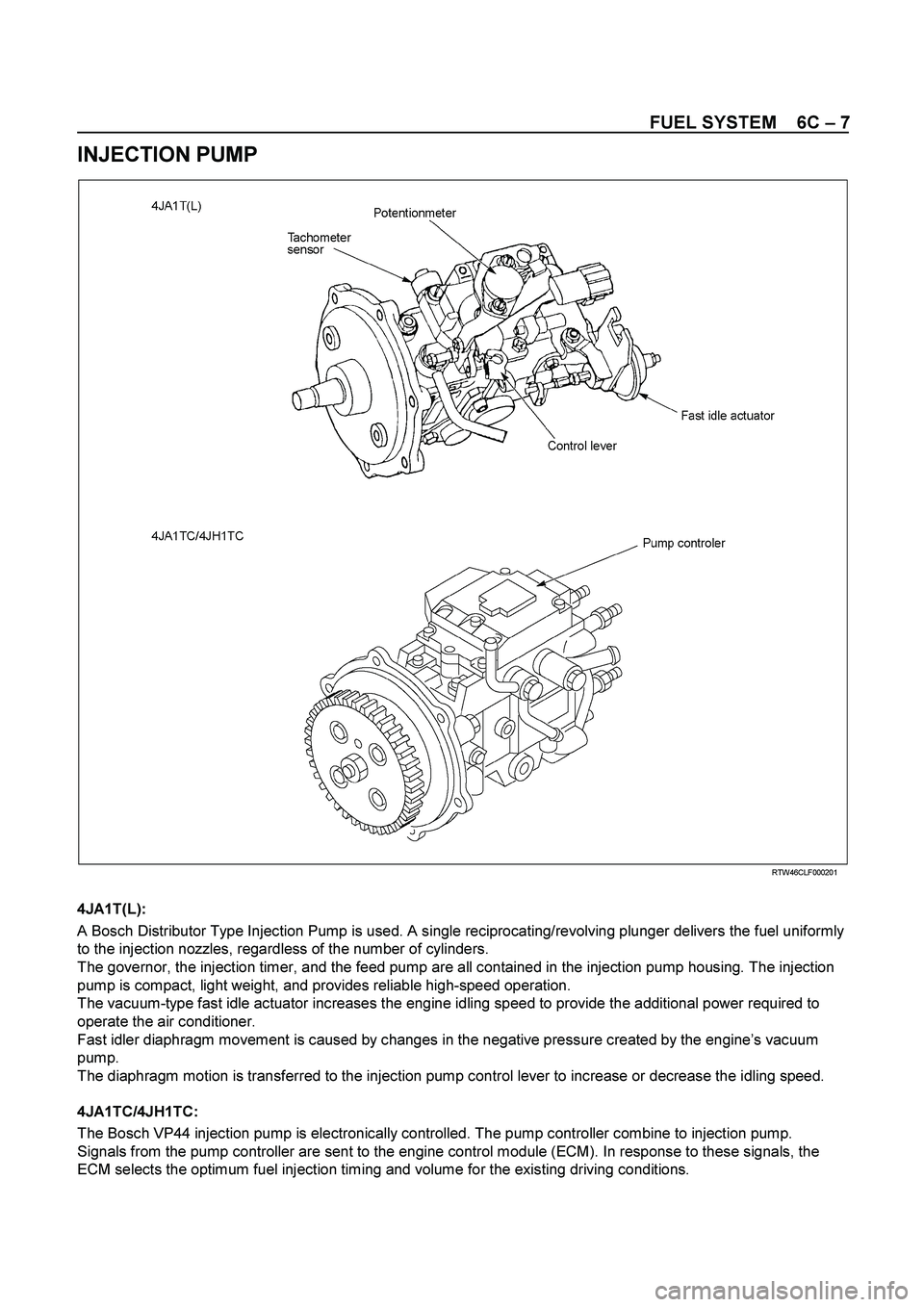
INJECTION PUMP
RTW46CLF000201
4JA1T(L):
A Bosch Distributor Type Injection Pump is used. A single reciprocating/revolving plunger delivers the fuel uniformly
to the injection nozzles, regardless of the number of cylinders.
The governor, the injection timer, and the feed pump are all contained in the injection pump housing. The injection
pump is compact, light weight, and provides reliable high-speed operation.
The vacuum-type fast idle actuator increases the engine idling speed to provide the additional power required to
operate the air conditioner.
Fast idler diaphragm movement is caused by changes in the negative pressure created by the engine’s vacuum
pump.
The diaphragm motion is transferred to the injection pump control lever to increase or decrease the idling speed.
4JA1TC/4JH1TC:
The Bosch VP44 injection pump is electronically controlled. The pump controller combine to injection pump.
Signals from the pump controller are sent to the engine control module (ECM). In response to these signals, the
ECM selects the optimum fuel injection timing and volume for the existing driving conditions.
Page 1340 of 4264
6D – 2 ENGINE ELECTRICAL
MAIN DATA AND SPECIFICATIONS
Description
Item
60A 80A
Generator
Type
AC generator with IC regulator and vacuum pump
Hitachi LR160-503E Hitachi LR180-513B
Voltage V
Drive and rotation
Ground polarity 12
V-belt, clockwise viewed from the drive pulley
Negative
Maximum output A 60 80
Engine speed ratio to 1 1.788
Maximum speed rpm 11,000
Weight with vacuum pump kg(lb) 5.8(12.8) 6.4(14.1)
Vacuum Pump
Delivery volume cm3/rev
Exhaust Characteristic
Maximum vacuum
50
-66.7 kPa (-500 mmHg) bulid up time 21 seconds or less at 1,000
rpm
7 seconds or less at 5,000 rpm
-90.7 kPa (-680 mmHg) or more
Starter Motor
Type
Solenoid controlled
Hitachi S13-555
12
2.3
8.76
300 Rated voltage V
Rated output kW
Load characteristics
Terminal voltage V
Load current A
Weight kg(Ib)
4.7 (10.4)
Page 1940 of 4264
6B-16 ENGINE COOLING (6VE1 3.5L)
Main Data and Specifications
General Specifications
M/T A/T
Cooling system Engine coolant forced circulation
Radiator Tube type corrugated
Heat radiation capacity 81.4 kw (70.004 kcal/h)
Heat radiation area 9.42m� (0.875ft�)
Radiator front area 0.28m� (0.026ft�)
Radiator dry weight 5.0kg (11.0lb) 5.2kg (11.4lb)
Radiator cap valve opening pressure 93.3 � 122.7kpa (13.5 � 17.8psi)
Engine coolant pump Centrifugal impeller type
Delivery 300 (317) or more
Pump speed 5000 � 50 rpm
Thermostat Wax pellet type with air hole
Valve opening temperature 74.5 � 78.5�C (166.1 � 173.3�F)
Engine coolant total capacity 12.3lit (13.0U.S qt) 12.2lit (12.9U.S qt)
Page 1985 of 4264
STARTING AND CHARGING SYSTEM (6VE1 3.5L) 6D3-13
Main Data and Specifications
General Specifications
Model ADX4IH
Rating
Voltage 12 V
Output 1.4 Kw
Time 30 sec
Number of teeth of pinion 9
Rotating direction(as viewed from pinion) Clockwise
Weight(approx.) 3.8kg (8.4lb)
No–load characteristics
Voltage /Current 11.5V/90A or less
Speed 3000rpm or more
Load characteristics
Voltage/current 8.5V/350A or less
Torque 13.2Nm (1.35kgm/9.77lb in.) or more
Speed 1000rpm or more
Locking characteristics
Voltage/current 2.4V/500A or less
Torque 11.8N�
�� �m (1.2kg�
�� �m/8.68lb in) or more
Page 1995 of 4264
STARTING AND CHARGING SYSTEM (6VE1 3.5L) 6D3-23
Main Data and Specifications
General Specifications
Parts Number 102211-1740
Model ACJV74
Rated voltage 12 V
Rated output 90 A
Rotating direction (As viewed from pulled) Clockwise
Pulley effective diameter 57.5 mm (2.26 in)
Weight 5.1 kg (11 lb)
Page 2052 of 4264

6E-56 3.5L ENGINE DRIVEABILITY AND EMISSIONS
GENERAL DESCRIPTION FOR FUEL
METERING
The fuel metering system starts with the fuel in the fuel
tank. An electric fuel pump, located in the fuel tank,
pumps fuel to the fuel rail through an in-line fuel filter.
The pump is designed to provide fuel at a pressure
above the pressure needed by the injectors.
A fuel pressure regulator in the fuel rail keeps fuel
available to the fuel injectors at a constant pressure.
A return line delivers unused fuel back to the fuel tank.
The basic function of the air/fuel metering system is to
control the air/fuel delivery to the engine. Fuel is
delivered to the engine by individual fuel injectors
mounted in the intake manifold.
The main control sensor is the heated oxygen senso
r
located in the exhaust system. The heated oxygen
sensor reports to the ECM how much oxygen is in the
exhaust gas. The ECM changes the air/fuel ratio to the
engine by controlling the amount of time that fuel
injector is "On".
The best mixture to minimize exhaust emissions is 14.7
parts of air to 1 part of gasoline by weight, which allows
the catalytic converter to operate most efficiently.
Because of the constant measuring and adjusting of the
air/fuel ratio, the fuel injection system is called a "closed
loop" system.
The ECM monitors signals from several sensors in
order to determine the fuel needs of the engine. Fuel is
delivered under one of several conditions called
"mode". All modes are controlled by the ECM.
Acceleration Mode
The ECM provides extra fuel when it detects a rapid
increase in the throttle position and the air flow.
Battery Voltage Correction Mode
When battery voltage is low, the ECM will compensate
for the weak spark by increasing the following:
� The amount of fuel delivered.
� The idle RPM.
� Ignition dwell time.
Clear Flood Mode
Clear a flooded engine by pushing the accelerator pedal
down all the way. The ECM then de-energizes the fuel
injectors. The ECM holds the fuel injectors de-
energized as long as the throttle remains above 80%
and the engine speed is below 800 RPM. If the throttle
position becomes less than 80%, the ECM again begins
to pulse the injectors "ON" and "OFF," allowing fuel into
the cylinders.
Deceleration Mode
The ECM reduces the amount of fuel injected when i
t
detects a decrease in the throttle position and the air
flow. When deceleration is very fast, the ECM may cu
t
off fuel completely for short periods.
Engine Speed/Vehicle Speed/Fuel Disable Mode
The ECM monitors engine speed. It turns off the fuel
injectors when the engine speed increase above 6400
RPM. The fuel injectors are turned back on when
engine speed decreases below 6150 RPM.
Fuel Cutoff Mode
No fuel is delivered by the fuel injectors when the
ignition is "OFF." This prevents engine run-on. In
addition, the ECM suspends fuel delivery if no reference
pulses are detected (engine not running) to preven
t
engine flooding.
Run Mode
The run mode has the following two conditions:
� Open loop
� Closed loop
When the engine is first started the system is in "open
loop" operation. In "open loop," the ECM ignores the
signal from the heated oxygen sensor (HO2S). I
t
calculates the air/fuel ratio based on inputs from the TP,
ECT, and MAF sensors.
The system remains in "open loop" until the following
conditions are met:
� The HO2S has a varying voltage output showing
that it is hot enough to operate properly (this
depends on temperature).
� The ECT has reached a specified temperature.
�
A specific amount of time has elapsed since
starting the engine.
� Engine speed has been greater than a specified
RPM since start-up.
The specific values for the above conditions vary with
different engines and are stored in the programmable
read only memory (PROM). When these conditions are
met, the system enters "closed loop" operation. In
"closed loop," the ECM calculates the air/fuel ratio
(injector on-time) based on the signal from the HO2S.
This allows the air/fuel ratio to stay very close to 14.7:1.
Page 2432 of 4264

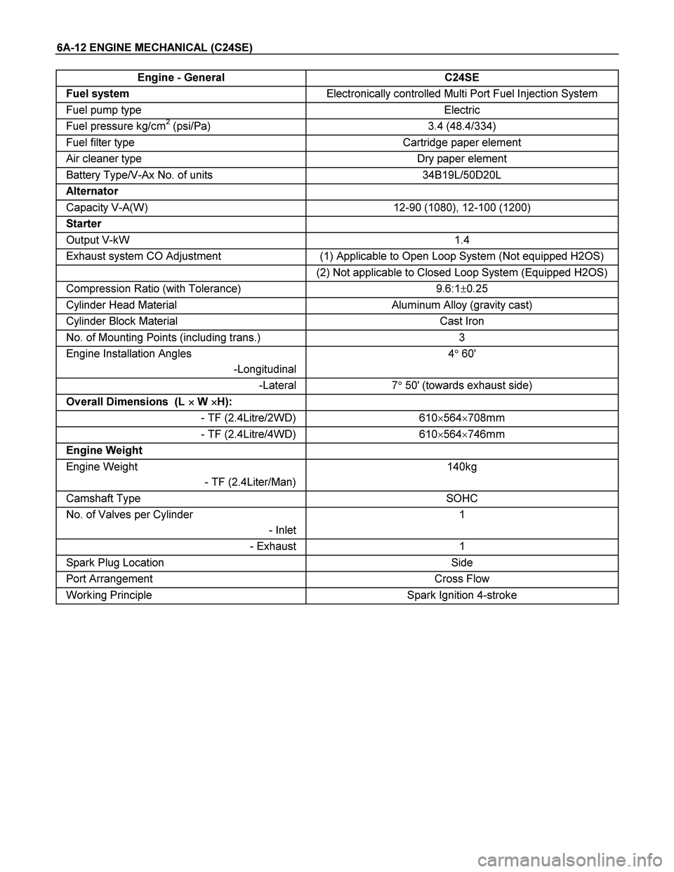
6A-12 ENGINE MECHANICAL (C24SE)
Engine - General C24SE
Fuel system Electronically controlled Multi Port Fuel Injection System
Fuel pump type Electric
Fuel pressure kg/cm2 (psi/Pa) 3.4 (48.4/334)
Fuel filter type Cartridge paper element
Air cleaner type Dry paper element
Battery Type/V-Ax No. of units 34B19L/50D20L
Alternator
Capacity V-A(W) 12-90 (1080), 12-100 (1200)
Starter
Output V-kW 1.4
Exhaust system CO Adjustment (1) Applicable to Open Loop System (Not equipped H2OS)
(2) Not applicable to Closed Loop System (Equipped H2OS)
Compression Ratio (with Tolerance) 9.6:1�0.25
Cylinder Head Material Aluminum Alloy (gravity cast)
Cylinder Block Material Cast Iron
No. of Mounting Points (including trans.) 3
Engine Installation Angles
-Longitudinal4� 60'
-Lateral 7� 50' (towards exhaust side)
Overall Dimensions (L �
�� � W �
�� �H):
- TF (2.4Litre/2WD) 610�564�708mm
- TF (2.4Litre/4WD) 610�564�746mm
Engine Weight
Engine Weight
- TF (2.4Liter/Man)140kg
Camshaft Type SOHC
No. of Valves per Cylinder
- Inlet1
- Exhaust 1
Spark Plug Location Side
Port Arrangement Cross Flow
Working Principle Spark Ignition 4-stroke
Page 2434 of 4264

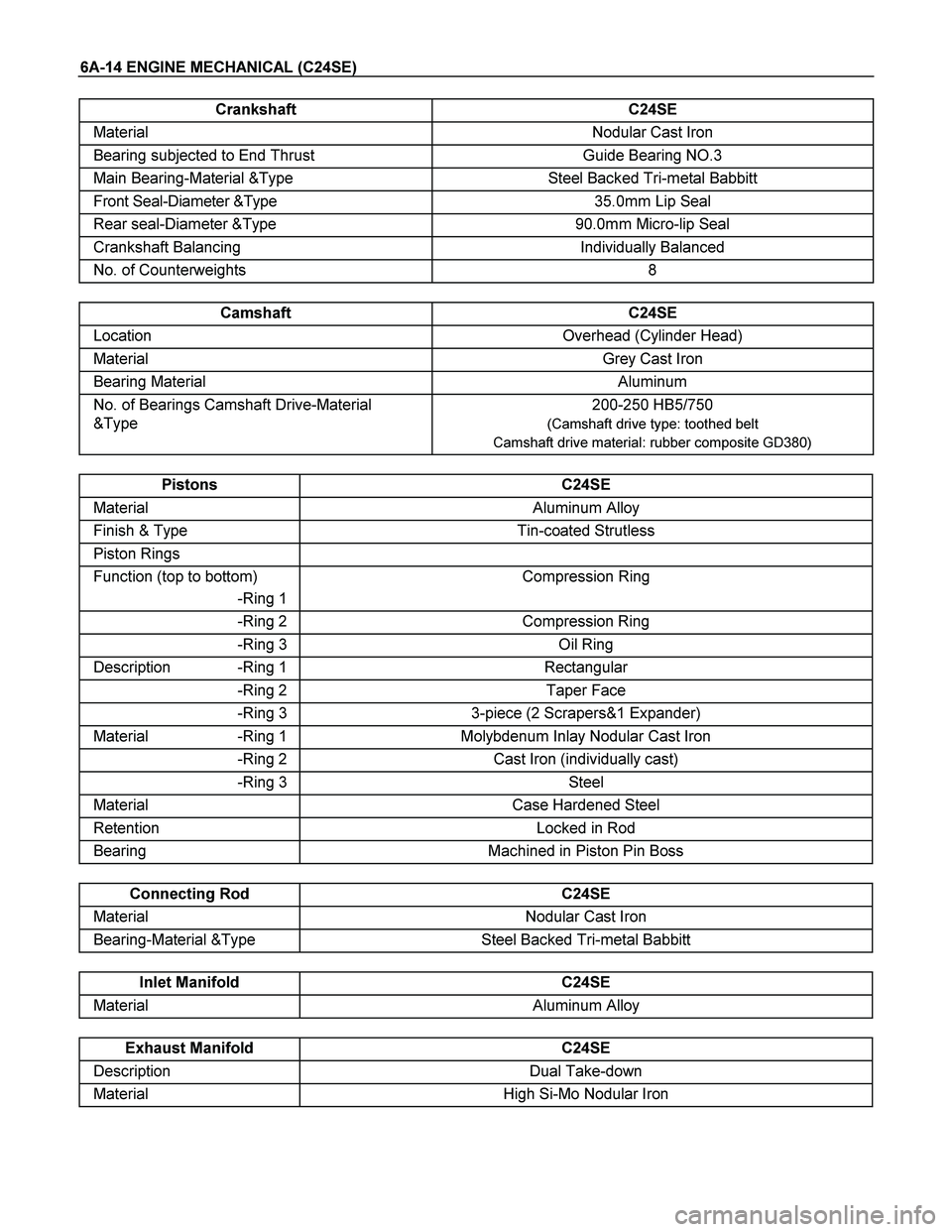
6A-14 ENGINE MECHANICAL (C24SE)
Crankshaft C24SE
Material Nodular Cast Iron
Bearing subjected to End Thrust Guide Bearing NO.3
Main Bearing-Material &Type Steel Backed Tri-metal Babbitt
Front Seal-Diameter &Type 35.0mm Lip Seal
Rear seal-Diameter &Type 90.0mm Micro-lip Seal
Crankshaft Balancing Individually Balanced
No. of Counterweights 8
Camshaft C24SE
Location Overhead (Cylinder Head)
Material Grey Cast Iron
Bearing Material Aluminum
No. of Bearings Camshaft Drive-Material
&Type 200-250 HB5/750
(Camshaft drive type: toothed belt
Camshaft drive material: rubber composite GD380)
Pistons C24SE
Material Aluminum Alloy
Finish & Type Tin-coated Strutless
Piston Rings
Function (top to bottom)
-Ring 1Compression Ring
-Ring 2 Compression Ring
-Ring 3 Oil Ring
Description -Ring 1 Rectangular
-Ring 2 Taper Face
-Ring 3 3-piece (2 Scrapers&1 Expander)
Material -Ring 1 Molybdenum Inlay Nodular Cast Iron
-Ring 2 Cast Iron (individually cast)
-Ring 3 Steel
Material Case Hardened Steel
Retention Locked in Rod
Bearing Machined in Piston Pin Boss
Connecting Rod C24SE
Material Nodular Cast Iron
Bearing-Material &Type Steel Backed Tri-metal Babbitt
Inlet Manifold C24SE
Material Aluminum Alloy
Exhaust Manifold C24SE
Description Dual Take-down
Material High Si-Mo Nodular Iron