2004 ISUZU TF SERIES key
[x] Cancel search: keyPage 2652 of 4264
6E–76 ENGINE DRIVEABILITY AND EMISSIONS
MISCELLANEOUS TEST
The state of each circuit can be tested by using
miscellaneous test menus. Especially when DTC
cannot be detected, a faulty circuit can be diagnosed by
testing each circuit by means of these menus.
Even DTC has been detected, the circuit tests using
these menus could help discriminate between a
mechanical trouble and an electrical trouble.
Connect Tech 2 and select “Powertrain”, “2.XL L4
HV240” & “Miscellaneous Test”.
F0: Lamps
F0: Malfunction Indicator Lamp
When the Tech 2 is operated, “Malfunction Indicator
Lamp (Check Engine Lamp)” is turned on or off.
The circuit is normal if the “Malfunction Indicator Lamp
(Check Engine Lamp)” in the instrument panel is turned
on or off in accordance with this operation.
F1: Relays
F0: Fuel Pump Relay
When the Tech 2 is operated, fuel pump relay signal
turns ON or OFF.
The circuit is normal if fuel pump sound is generated in
accordance with this operation when key switch is
turned ON.
F1: A /C Clutch Relay
When the Tech 2 is operated, A/C clutch relay signal
turns ON or OFF.
The circuit is normal if A/C compressor clutch is
energized in accordance with this operation when the
engine is running.
F2: EVAP
F0: Purge Solenoid
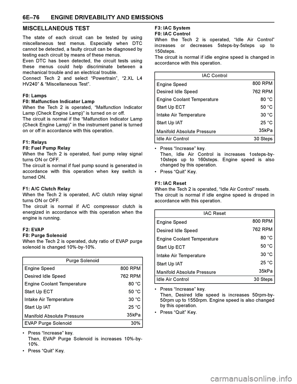
When the Tech 2 is operated, duty ratio of EVAP purge
solenoid is changed 10%-by-10%.
Press “Increase” key.
Then, EVAP Purge Solenoid is increases 10%-by-
10%.
Press “Quit” Key.F3: IAC System
F0: IA C Control
When the Tech 2 is operated, “Idle Air Control”
increases or decreases 5steps-by-5steps up to
150steps.
The circuit is normal if idle engine speed is changed in
accordance with this operation.
Press “Increase” key.
Then, Idle Air Control is increases 1osteps-by-
10steps up to 160steps. Engine speed is also
changed by this operation.
Press “Quit” Key.
F1: IA C Reset
When the Tech 2 is operated, “Idle Air Control” resets.
The circuit is normal if idle engine speed is droped in
accordance with this operation.
Press “Increase” key.
Then, Desired Idle speed is increases 50rpm-by-
50rpm up to 1550rpm. Engine speed is also changed
by this operation.
Press “Quit” Key. Purge Solenoid
Engine Speed 800 RPM
Desired Idle Speed 762 RPM
Engine Coolant Temperature 80 °C
Start Up ECT 50 °C
Intake Air Temperature 30 °C
Start Up IAT 25 °C
Manifold Absolute Pressure 35kPa
EVAP Purge Solenoid 30%
IAC Control
Engine Speed 800 RPM
Desired Idle Speed 762 RPM
Engine Coolant Temperature 80 °C
Start Up ECT 50 °C
Intake Air Temperature 30 °C
Start Up IAT25 °C
Manifold Absolute Pressure 35kPa
Idle Air Control 30 Steps
IAC Reset
Engine Speed 800 RPM
Desired Idle Speed 762 RPM
Engine Coolant Temperature 80 °C
Start Up ECT 50 °C
Intake Air Temperature 30 °C
Start Up IAT 25 °C
Manifold Absolute Pressure 35kPa
Idle Air Control 30 Steps
Page 2653 of 4264
ENGINE DRIVEABILITY AND EMISSIONS 6E–77
F4: Injector Balance Test
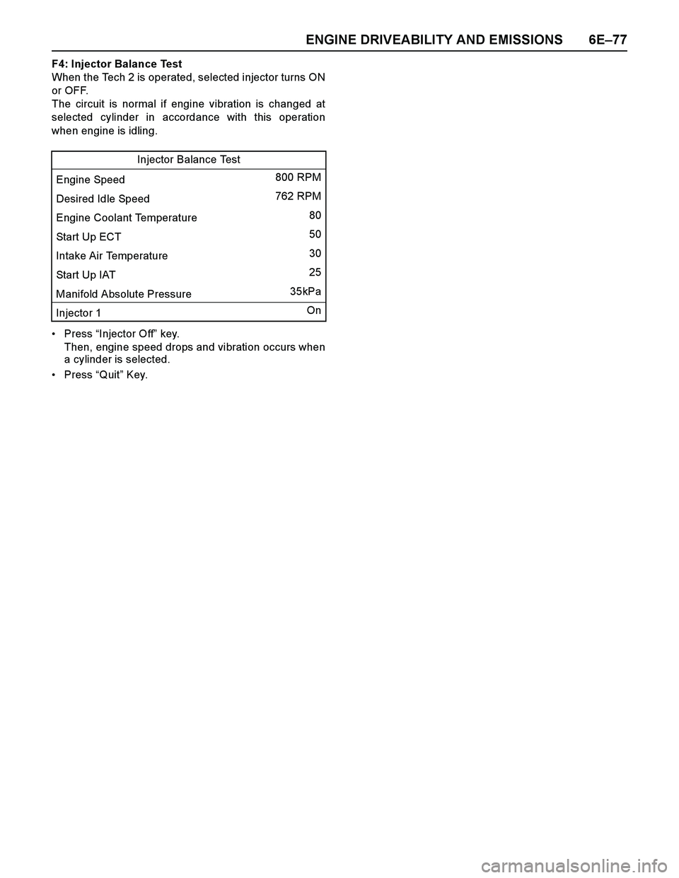
When the Tech 2 is operated, selected injector turns ON
or OFF.
The circuit is normal if engine vibration is changed at
selected cylinder in accordance with this operation
when engine is idling.
Press “Injector Off” key.
Then, engine speed drops and vibration occurs when
a cylinder is selected.
Press “Quit” Key.Injector Balance Test
Engine Speed 800 RPM
Desired Idle Speed 762 RPM
Engine Coolant Temperature 80
Start Up ECT 50
Intake Air Temperature 30
Start Up IAT 25
Manifold Absolute Pressure 35kPa
Injector 1 On
Page 2660 of 4264
6E–84 ENGINE DRIVEABILITY AND EMISSIONS
SERVICE PROGRAMMING SYSTEM (SPS)
The procedure to program the control unit by using the
Service Programming System (SPS) software contained
in TIS2000 is ex plained below.
NOTE:
If the Engine Control Module (ECM) was
programmed, the Immobilizer System must be
linked to the ECM: Refer to section 11
“Immobilizer System-ECM replacement” for the
ECM/Immobilizer linking procedure.
Should Tech2 display "SPS Procedure was not
successful", engine will not start, but no DTCs
are present, low battery voltage or poor electrical
connections should be the primary suspects.
Perform the SPS procedure again after rectifying
the fault/s.IMPORTANT:
Perform the following checks before attempting to
program the control unit:
The Tech2 PCMCIA card is programmed with The
latest software release.
The latest release of TIS2000 is loaded on the PC.
The vehicle battery is fully charged.
The control unit to be programmed is connected
to the vehicle.
1. Preparations of TIS 2000
1. Connect Tech 2 to P/C.
2. Check to see if Hardware Key is plugged into Port.
3. Activate TIS 2000 by P/C.
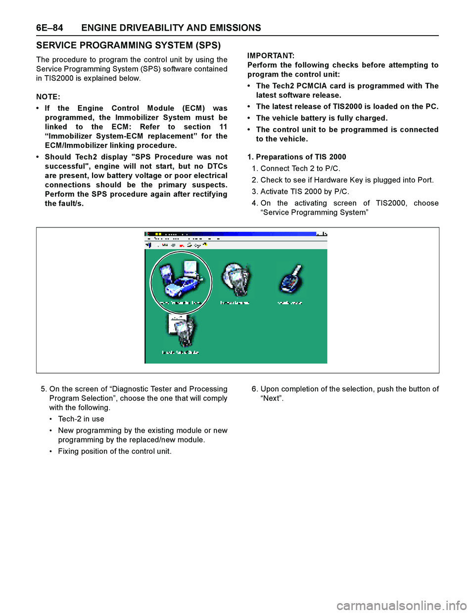
4. On the activating screen of TIS2000, choose
“Service Programming System”
5. On the screen of “Diagnostic Tester and Processing
Program Selection”, choose the one that will comply
with the following.
Tech-2 in use
New programming by the ex isting module or new
programming by the replaced/new module.
Fix ing position of the control unit.6. Upon completion of the selection, push the button of
“Nex t”.
Page 2694 of 4264
6E–118 ENGINE DRIVEABILITY AND EMISSIONSP1167 D Fuel Supply System Rich During
Deceleration Fuel Cutoff1. No DTC relating to MAP sensor, TPS,
EVAP purge, ECT sensor, CKP sensor,
VSS, injector control circuit and ignition
control circuit.
2. O
2 sensor bank 1 output voltage is more
than 550mV in deceleration fuel cutoff
mode.No fail-safe function. O
2 sensor output voltage is below 550mV. 1. Sensor harness open or short to ground
circuit.
2. O
2 sensor malfunction.
3. MAF sensor output is incorrect.
4. Air intake line malfunction.
5. IAC valve malfunction.
6. Low fuel pressure.
7. Injector malfunction.
8. EVAP purge solenoid valve malfunction.
9. Ignition system malfunction.
10. Spark plug malfunction.
11. ECM malfunction.J2-6/
J2-21
P1171 D Fuel Supply System Lean During Power
Enrichment 1. No DTC relating to MAP sensor, TPS,
EVAP purge, ECT sensor, CKP sensor,
VSS, injector control circuit and ignition
control circuit.
2. Engine coolant temperature is more than
60deg. C.
3. Mass air flow is below 13.5m/s.
4. O
2 sensor bank 1 output voltage is below
350mV in power enrichment mode. No fail-safe function. O
2 sensor output voltage is more than
350mV.1. Sensor harness open or short to ground
circuit.
2. O
2 sensor malfunction.
3. MAF sensor output is incorrect.
4. Air intake line malfunction.
5. IAC valve malfunction.
6. Low fuel pressure.
7. Injector malfunction.
8. ECM malfunction.J2-6/
J2-21
P1625 B ECM System Reset ECM reset has occurred other than “On”. Engine control disabled. Memory are is OK. 1. Electrical interference.
2. Magnetic interference.
3. ECM malfunction.-
P1626 - Immobilizer No Signal No response from immobilizer control unit. 1. Engine does not start.
2. Check engine lamp flash.No recovery. 1. ECM and immobilizer control unit
communication circuit open circuit, short to
ground circuit or short to voltage circuit.
2. ECM malfunction.
3. Immobilizer control unit malfunction.
4. Transponder key malfunction.J2-23/
J2-32
P1631 - Immobilizer Wrong Signal Received response is not correct.1. ECM malfunction.
2. Immobilizer control unit malfunction.
3. Transponder key malfunction.-
P1648 - Wrong Security Code Entered Received incorrect security code.1. ECM malfunction.
2. Immobilizer control unit malfunction.
3. Transponder key malfunction.-
P1649 - Immobilizer Function Not Programmed Immobilizer function is not programmed in the
ECM.ECM malfunction. -
P1693 B Tachometer Output Low Voltage Tacho output circuit short to ground circuit. No fail-safe function. Tacho output circuit is correct condition. 1. Tacho output circuit short to ground circuit.
2. Poor connector connection.
3. ECM malfunction.J2-25 Code Type DTC Name DTC Setting Condition Fail-Safe (Back Up) Recovery Condition Related Failure Parts Related
ECM
Pin No.
Page 2802 of 4264
6E–226 ENGINE DRIVEABILITY AND EMISSIONS
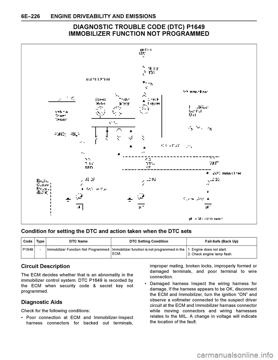
DIAGNOSTIC TROUBLE CODE (DTC) P1649
IMMOBILIZER FUNCTION NOT PROGRAMMED
Condition for setting the DTC and action taken when the DTC sets
Circuit Description
The ECM decides whether that is an abnomality in the
immobilizer control system. DTC P1649 is recorded by
the ECM when security code & secret key not
programmed.
Diagnostic Aids
Check for the following conditions:
Poor connection at ECM and Immobilizer-Inspect
harness connectors for backed out terminals,improper mating, broken locks, improperly formed or
damaged terminals, and poor terminal to wire
connection.
Damaged harness Inspect the wiring harness for
damage, If the harness appears to be OK, disconnect
the ECM and Immobilizer, turn the ignition “ON” and
observe a voltmeter connected to the suspect driver
circuit at the ECM and Immobilizer harnass connector
while moving connectors and wiring harnesses
relates to the MIL. A change in voltage will indicate
the location of the fault.
Code Type DTC Name DTC Setting Condition Fail-Safe (Back Up)
P1649 - Immobilizer Function Not Programmed Immobilizer function is not programmed in the
ECM.1. Engine doe s no t start.
2. Check engine lamp flash.
Page 2837 of 4264
ENGINE DRIVEABILITY AND EMISSIONS 6E–261
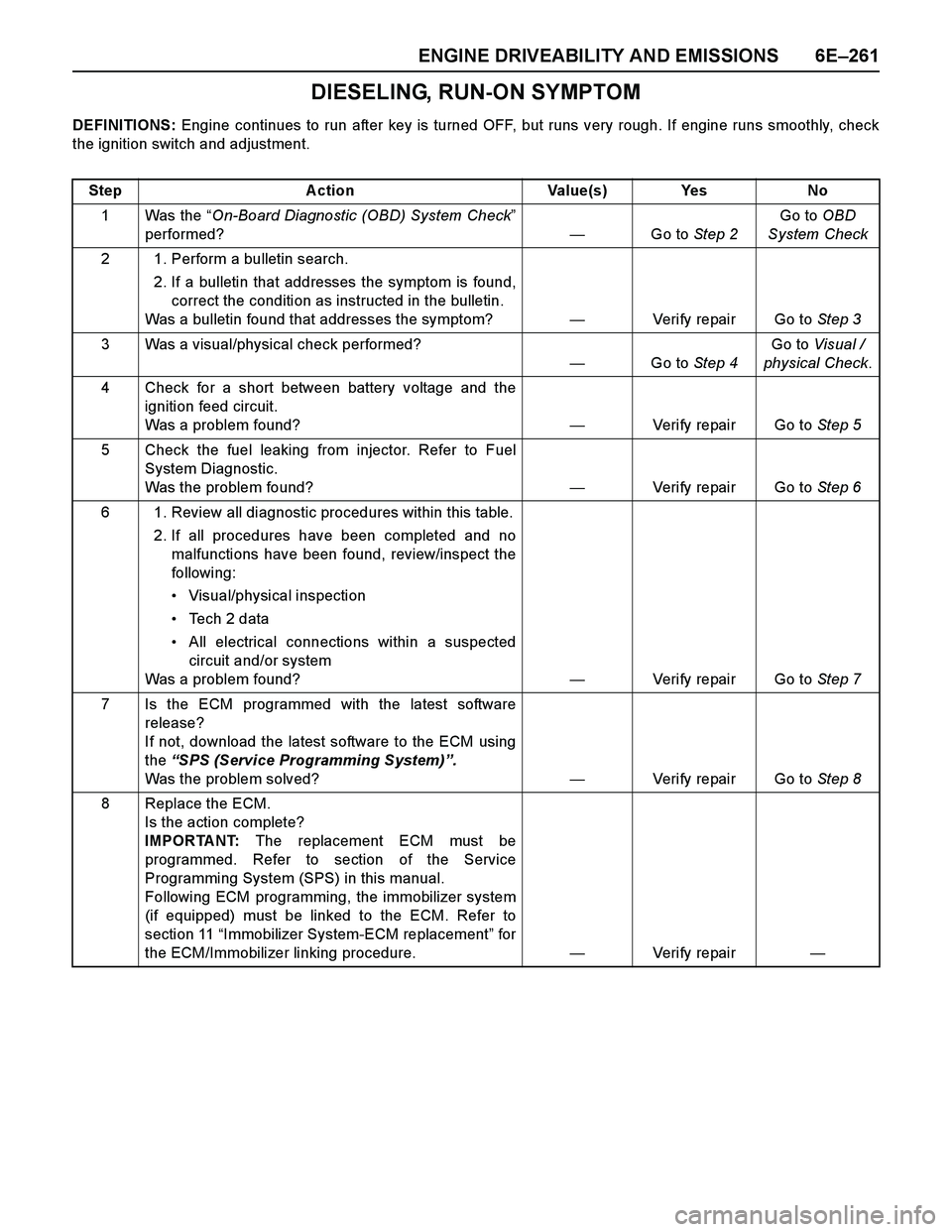
DIESELING, RUN-ON SYMPTOM
DEFINITIONS: Engine continues to run after key is turned OFF, but runs very rough. If engine runs smoothly, check
the ignition switch and adjustment.
Step Action Value(s) Yes No
1Was the “On-Board Diagnostic (OBD) System Check”
performed?—Go to Step 2Go to OBD
System Check
2 1. Perform a bulletin search.
2. If a bulletin that addresses the symptom is found,
correct the condition as instructed in the bulletin.
Was a bulletin found that addresses the symptom?—Verify repair Go to Step 3
3 Was a visual/physical check performed?
—Go to Step 4Go to Visual /
physical Check.
4 Check for a short between battery voltage and the
ignition feed circuit.
Was a problem found?—Verify repair Go to Step 5
5 Check the fuel leaking from injector. Refer to Fuel
System Diagnostic.
Was the problem found?—Verify repair Go to Step 6
6 1. Review all diagnostic procedures within this table.
2. If all procedures have been completed and no
malfunctions have been found, review/inspect the
followi ng:
Visual/physical inspection
Te c h 2 d a t a
All electrical connections within a suspected
circuit and/or system
Was a problem found?—Verify repair Go to Step 7
7 Is the ECM programmed with the latest software
release?
If not, download the latest software to the ECM using
the “SPS (Service Programming System)”.
Was the problem solved?—Verify repair Go to Step 8
8 Replace the ECM.
Is the action complete?
IMPORTANT: The replacement ECM must be
programmed. Refer to section of the Service
Programming System (SPS) in this manual.
Following ECM programming, the immobilizer system
(if equipped) must be linked to the ECM. Refer to
section 11 “Immobilizer System-ECM replacement” for
the ECM/Immobilizer linking procedure.—Veri fy repai r—
Page 3287 of 4264
IMMOBILIZER SYSTEM 11A-1
SECTION 11A
IMMOBILIZER SYSTEM
CONTENTS
Service Precaution.................................................
11A-2
General Description...............................................
11A-3
What happens without proper transponder
operation? ..........................................................
11A-6
No proper transponder is available, what
should be done for the system? ......................
11A-6
Caution to the operation.....................................
11A-6
Summary of operation........................................
11A-6
What your organization should provide for
your customer ....................................................
11A-6
Car Pass .............................................................
11A-6
Security code management ..............................
11A-6
Essential tool (Scan tool : Tech-2) ..................
11A-6
Circuit Diagram .................................................
11A-7
Parts Location.........................................................
11A-10
Immobilizer control unit (ICU); For Electronic
Control Engine (6VE1, C24SE, 4JH1-TC,
4JA1-TC) .......................................................... 11A-11
Pin-outs; For Electronic Control Engine
(6VE1, C24SE, 4JH1-TC, 4JA1-TC)...............
11A-12
Immobilizer control unit (ICU); Mechanical
Control Engine (4JA1-T) .................................. 11A-13
Immobilizer coil (Antenna) ...................................
11A-15
Transponder (Key) ............................................ 11A-15
Immobilizer warning lamp ................................. 11A-15
Engine control module (ECM) .......................... 11A-15
Car Pass Card .................................................. 11A-16
Loss of car pass card.........................................
11A-16
Instructions on Filling Out the form "Data
request, car pass" .............................................
11A-16
Important Instructions ........................................
11A-17
lmportant information on Programming .............
11A-19
Security code ......................................................
11A-19
Entering a code ..................................................
11A-19
Transponder (Key) .............................................
11A-19
Important .............................................................
11A-19
Tech-2 Scan Tool ..................................................
11A-20
Tech-2 Features .................................................
11A-21
Getting Started ...................................................
11A-21
Operating Procedure .........................................
11A-22
Menu ....................................................................
11A-23
DTC ......................................................................
11A-23
Clear DTC Information .......................................
11A-23
Tech-2 Data Display ...........................................
11A-23
Check Vehicle Identification Number (VIN) ....
11A-23
Reset Immobilizer (Reset Immobilizer
Control Unit) .......................................................
11A-23
Reset Engine Control Module (Reset ECM) ...
11A-24
Erase transponder key .......................................
11A-24
Programming Immobilizer Function .................
11A-25
Programming ICU ...............................................
11A-26
Programming ECM .............................................
11A-27
Programming ICU and ECM .............................
11A-28
Transponder program ........................................
11A-28
Data List ...............................................................
11A-30
Diagnostic procedure ............................................
11A-31
Clearing Diagnostic Trouble Codes ....................
11A-31
Verifying Vehicle Repair ........................................
11A-31
Diagnostic Aids ......................................................
11A-31
Check the condition for system parts ..............
11A-31
Check the Electro-Magnetic Interference
(EMI) ....................................................................
11A-31
Check the other items ........................................
11A-31
Check the operation ...........................................
11A-31
Diagnostic Trouble Code (DTC) list ....................
11A-32
IMMOBILIZER SYSTEM CHECK ........................
11A-33
NO IMMOBILIZER WARNING LAMP .................
11A-36
IMMOBILIZER WARNING LAMP ON STEADY 11A-37
B0001 REPLACE ELECTRONIC CONTROL
UNIT (ECU) (IMMOBILIZER FAULT) ................
11A-38
B0002 IMMOBILIZER NOT PROGRAMMED ....
11A-39
B0003 TRANSPONDER KEY PROBLEM ..........
11A-40
B0004 IMMOBILIZER COIL CIRCUIT
(ANTENNA COIL FAULT) ...................................
11A-42
B0005 COMMUNICATION LINE W VOLTAGE
LOW .......................................................................
11A-43
B0006 COMMUNICATION LINE W VOLTAGE
HIGH .......................................................................
11A-44
B0007 NO ENGINE REQUEST RECEIVED ......
11A-45
B0008 WRONG TRANSPONDER KEY .............
11A-47
B0009 NO TRANSPONDER KEY
PROGRAMMED ...................................................
11A-48
Page 3288 of 4264
11A-2 IMMOBILIZER SYSTEM
B0010 UNKNOWN TRANSPONDER KEY .......
11A-49
B0011 TRANSPONDER KEY PROBLEM
(Only 4JA1-T Engine) ...................................... 11A-50
B0012 WRONG TRANSPONDER KEY
(Only 4JA1-T Engine) ...................................... 11A-52
B0013 IMMOBILIZER NOT PROGRAMMED
(Only 4JA1-T Engine) ...................................... 11A-53
B0014 NO TRANSPONDER KEY
PROGRAMMED (Only 4JA1-T Engine) ........... 11A-54
B0015 VEHICLE SPEED SIGNAL LOW
(Only 4JA1-T Engine) ....................................... 11A-55
B0016 VEHICLE SPEED SIGNAL HIGH
(Only 4JA1-T Engine) ...................................... 11A-56
B0023 IMMOBILIZER COIL CIRCUIT
(ANTENNA COIL FAULT)
(Only 4JA1-T Engine) ...................................... 11A-57
B0024 WRONG TRANSPONDER KEY
(Only 4JA1-T Engne) ....................................... 11A-58
B0055 EEPROM ERROR ................................. 11A-59
Special Tool ............................................................
11A-60
Service Precaution
WARNING: THIS VEHICLE HAS A SUPPLEMENTAL
RESTRAINT SYSTEM (SRS). REFER TO THE SRS
COMPONENT AND WIRING LOCATION VIEW IN
ORDER TO DETERMINE WHETHER YOU ARE
PERFORMING SERVICE ON OR NEAR THE SRS
COMPONENTS OR THE SRS WIRING. WHEN YOU
ARE PERFORMING SERVICE ON OR NEAR THE
SRS COMPONENTS OR THE SRS WIRING, REFE
R
TO THE SRS SERVICE INFORMATION. FAILURE TO
FOLLOW WARNINGS COULD RESULT IN
POSSIBLE AIR BAG DEPLOYMENT, PERSONAL
INJURY, OR OTHERWISE UNNEEDED SRS SYSTEM
REPAIRS.
CAUTION: Always use the correct fastener in the
proper location. When you replace a fastener, use
ONLY the exact part number for that application.
ISUZU will call out those fasteners that require a
replacement after removal. ISUZU will also call out
the fasteners that require thread lockers or thread
sealant. UNLESS OTHERWISE SPECIFIED, do not
use supplemental coatings (Paints, greases, o
r
other corrosion inhibitors) on threaded fasteners o
r
fastener joint interfaces. Generally, such coatings
adversely affect the fastener torque and the joint
clamping force, and may damage the fastener.
When you install fasteners, use the correct
tightening sequence and specifications. Following
these instructions can help you avoid damage to
parts and systems.