Page 1006 of 4264
8A-348 ELECTRICAL-BODY AND CHASSIS
Door mirror side
D-2 D-7
2. Door Mirror Connector Circuit
Disconnect the door mirror connector, apply the battery
voltage to the door mirror side connector (
D-2 and D-7)
terminals and check its function.
Connector No.
D-2 D-7
Terminal No.
Operation 1 2 4
Up - +
Down + -
Left + -
Right - +
Page 1011 of 4264

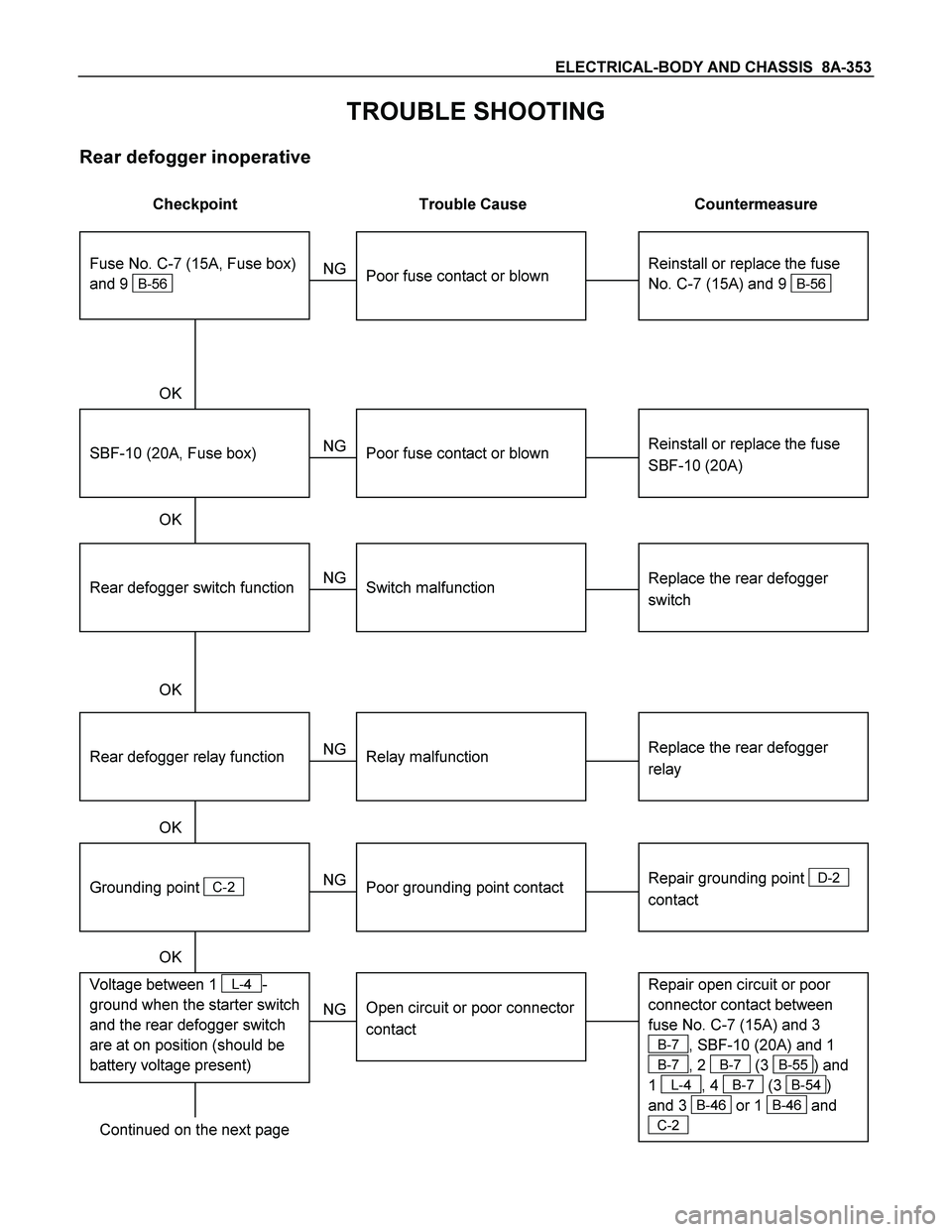
ELECTRICAL-BODY AND CHASSIS 8A-353
TROUBLE SHOOTING
Rear defogger inoperative
Checkpoint Trouble Cause Countermeasure
Reinstall or replace the fuse
No. C-7 (15A) and 9
B-56
Poor fuse contact or blown
NG
Reinstall or replace the fuse
SBF-10 (20A)
SBF-10 (20A, Fuse box)
Poor fuse contact or blown
Replace the rear defogger
switch
Rear defogger switch function
Switch malfunction
NG NG OK
OK OK
Fuse No. C-7 (15A, Fuse box)
and 9
B-56
Replace the rear defogger
relay
Relay malfunction
NG
Continued on the next page
Rear defogger relay function
Repair grounding point
D-2
contact
Grounding point
C-2
Poor grounding point contact
NG OK
Repair open circuit or poor
connector contact between
fuse No. C-7 (15A) and 3
B-7, SBF-10 (20A) and 1
B-7, 2 B-7 (3 B-55) and
1
L-4, 4 B-7 (3 B-54)
and 3
B-46 or 1 B-46 and
C-2
Voltage between 1 L-4-
ground when the starter switch
and the rear defogger switch
are at on position (should be
battery voltage present)
Open circuit or poor connector
contact
NG OK
Page 1014 of 4264
8A-356 ELECTRICAL-BODY AND CHASSIS
INSPECTION AND REPAIR
Switch side
B-57
REAR DEFOGGER SWITCH
Rear Defogger Switch Connections
Terminal No.
SW position 9 7 8
ON
OFF
B-7
REAR DEFOGGER RELAY
Check continuity between the relay terminals.
2- 1......................... No continuity
(When battery voltage is applied between
4 and 3)
2- 1......................... Continuity
INSPECTION OF REAR DEFOGGER HEAT
WIRE
� Heat wires are printed on the inner side of glass.
To clean, use a soft cloth and wipe horizontally along the
wires.
� Never use glass cleaner or equivalent.
� When measuring voltage, wind a piece of tin foil around the
tip of the negative probe and press the foil against the wire
with your finger as shown.
(1) Turn the ignition switch on.
(2) Turn the defogger switch on.
(3) Measure the voltage between the three points on the hea
t
wire and the (-) terminal with a voltmeter.
(4) Check that the voltage becomes smaller from
A to B to C.
Page 1049 of 4264
ELECTRICAL-BODY AND CHASSIS 8A-391
Remote key
Remove Key Assembly
Replacing the battery in the remote control unit
Replace the battery as soon as the range of the remote control
starts to become reduced.
Open the underside of the remote control unit by removing the
battery cover with a screwdriver as shown in the illustration.
Replace the battery, ensuring that it is inserted correctly.
Replace the battery cover so that it engages audibly. The
battery change must be performed within 3 minutes, otherwise
the remote control will have to be reprogrammed. Make sure
that you dispose of old batteries in accordance with
environmental protection regulations.
604RW055
Page 1068 of 4264
8A-410 ELECTRICAL-BODY AND CHASSIS
ANTI THEFT INDICATOR
Removal
1. Disconnect the battery ground cable.
RTW3A0SH001301
2. Remove the side ventilation grille.
RTW08ASH000101
3. Disconnect the indicator connector and screw from the
backside of the side ventilation grille to remove the anti thef
t
indicator.
Installation
To install, follow the removal steps in the reverse order, noting
the following point.
1. Push in the switch with your fingers until it locks securely.
Page 1091 of 4264
ELECTRICAL-BODY AND CHASSIS 8A-433
No. Connector face No. Connector face
H-1
White
Battery (+) ~ Engine room H-10
WhiteINST ~ Front Door-RH
H-2
NOT USED H-11
NOT USED
H-3
(6VE1,
4JH1-TC)
White Battery (+) ~ Engine room H-12
BlackINST ~ Roof
H-4
(C24SE)
White Engine room ~ Mission H-13
WhiteINST ~ Door -LH
H-4
(6VE1,
4JA1-TC,
4JH1-TC)
White
Engine ~ Engine room H-14
WhiteRear body ~ Rear door-LH
H-5
NOT USED H-15
White
Engine room ~ Chassis
H-6
White
Engine room ~ INST H-16
WhiteRear body ~ Rear door-RH
H-7
White
Engine room ~ INST H-17
WhiteChassis ~ License plate lamp
H-8
NOT USED H-18
White
Engine room ~ INST
H-9
Blue
Engine room ~ Chassis H-19
~
H-21 NOT USED
Page 1092 of 4264
8A-434 ELECTRICAL-BODY AND CHASSIS
No. Connector face No. Connector face
H-22
(6VE1)
(4JH1-TC)
White Engine ~ Engine room C H-31
(C24SE)
Engine room ~ Mission
H-23
(6VE1)
(4JH1-TC)
White Engine ~ Engine room B H-32
(C24SE)
(6VE1)
Engine room ~ Rear body
H-23
(4JA1-L)
White Engine room B ~ T/misson H-33
(4JH1-TC)
Engine ~ Engine room
H-24
Black
INST ~ Front door-RH H-34
(C24SE)
Engine ~ Engine room
H-25
Black
INST ~ Front door-LH H-35
Trailer
H-26
White
INST ~ Rear body
H-27
Black
INST ~ Rear body
H-28
White
Sub harness connector
H-29
(C24SE)
Battery(+) ~ Engine room
H-30
(6VE1)
(4JH1-TC)
Engine room ~ INST
Page 1095 of 4264
ELECTRICAL-BODY AND CHASSIS 8A-437
No. Connector face No. Connector face
P-1
Silver
Battery (+) P-9
SilverACG (B)
P-2
Silver
Relay & Fuse box P-10
SilverEngine ground
P-3
Brown
Starter (S) P-11
SilverFuse & relay box
P-4
Silver
Starter (B) P-12
NOT USED
P-4
Silver
Starter (B) P-13
Gray Shift on the fly actuator
P-5
Silver
Battery (-) P-14
WhiteFuse & relay box
P-6
Silver
Body earth (Ground) P-15
Silver2nd battery (+)
P-7
NOT USED P-16
Silver
2nd battey (-)
P-8
(C24SE)
(4JH1-TC
Green ACG (L)
P-8
(6VE1)
White ACG (L)