Page 1101 of 4264
. REFER TO THE SRS
COMPONENT AND WIRING LOCATION VIEW IN ORDER TO DETERMINE WHETHER YOU")
CRUISE CONTROL SYSTEM 8B-3
Service Precaution
WARNING: THIS VEHICLE HAS A SUPPLEMENTAL RESTRAIN SYSTEM (SRS). REFER TO THE SRS
COMPONENT AND WIRING LOCATION VIEW IN ORDER TO DETERMINE WHETHER YOU ARE
PERFORMING SERVICE ON OR NEAR THE SRS COMPONENTS OR THE SRS WIRING. WHEN YOU ARE
PERFORMING SERVICE ON OR NEAR THE SRS COMPONENTS OR THE SRS WIRING, REFER TO THE SRS
SERVICE INFORMATION. FAILURE TO FOLLOW WARNINGS COULD RESULT IN POSSIBLE AIR BAG
DEPLOYMENT, PERSONAL INJURY, OR OTHER WISE UNNEEDED SRS SYSTEM REPAIRS.
CAUTION: Always use the correct fastener in the proper location. When you replace a faster, use ONLY the
exact part number for that application. Dealer will call out those fasteners that require a replacement after
removal. Dealer will also call out the fasteners that require thread lockers or thread sealant. UNLESS
OTHERWISE SPECIFIED, do not use supplemental coatings (Paints, greases, or other corrosion inhibitors)
on threaded fasteners or fastener joint interfaces. Generally, such coatings adversely affect the fastener
torque and joint Clamping force, and may damaged the fastener. When you install fasteners, use the
correct tightening sequence and specifications. Following these instructions can help you avoid damage to
parts and systems.
General Description
The cruise control keeps the vehicle running at a fixed speed until a signal canceling this fixed speed is received.
When the main switch “AUTO CRUISE” is turned on with the vehicle in the running mode, the battery voltage is
applied to the control unit. When a signal from the control unit while the vehicle is in this state, the cruise control
actuator is activated to operate the system. Also, while the system is operating, the “AUTO CRUISE” indicator light
in the meter assembly lights up.
LTW48BSH000101
1. SET/COAST Switch Function
1. Set Function: When the SET/COAST switch is pressed and released with the main switch on, the speed at
which the vehicle is running at that moment is stored in the memory, and the vehicle automatically runs at the
stored speed.
2. COAST-down Function: When the SET/COAST switch is kept on while the vehicle in running, the vehicle
decelerates during that time. The speed at which vehicle is running when the control switch is pressed in the
memory, and the vehicle automatically returns to the stored speed.
3. Tap-down Function: When the SET/COAST switch is pressed and released instantaneously while the
vehicle is running, the vehicle decelerates a mile for each on/off operation. The vehicle speed at which the
vehicle was running when the SET/COAST was released last is stored in the memory, and the vehicle
automatically returns to this stored speed.
Page 1103 of 4264
CRUISE CONTROL SYSTEM 8B-5
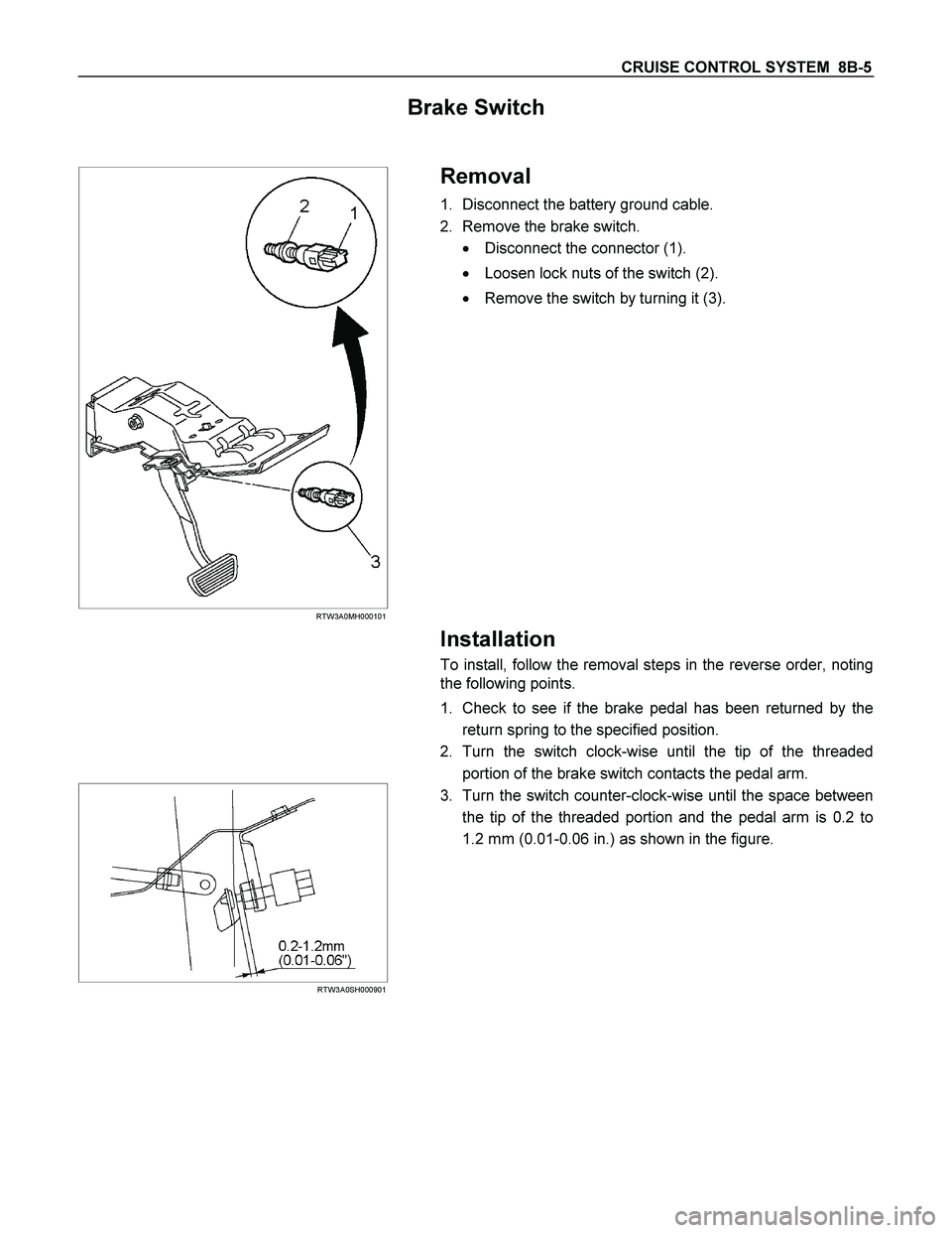
Brake Switch
RTW3A0MH000101
Removal
1. Disconnect the battery ground cable.
2. Remove the brake switch.
� Disconnect the connector (1).
� Loosen lock nuts of the switch (2).
� Remove the switch by turning it (3).
Installation
To install, follow the removal steps in the reverse order, noting
the following points.
1. Check to see if the brake pedal has been returned by the
return spring to the specified position.
2. Turn the switch clock-wise until the tip of the threaded
portion of the brake switch contacts the pedal arm.
RTW3A0SH000901
3. Turn the switch counter-clock-wise until the space between
the tip of the threaded portion and the pedal arm is 0.2 to
1.2 mm (0.01-0.06 in.) as shown in the figure.
Page 1105 of 4264
CRUISE CONTROL SYSTEM 8B-7
Cruise Control Main Switch
Removal
1. Disconnect the battery ground cable.
RTW3A0SH001301
2. Remove the side ventilation grille.
RTW3A0SH001401
3. Disconnect the switch connector and push the lock from the
backside of the side ventilation grille to remove the cruise
control main switch.
Installation
To install, follow the removal steps in the reverse order, noting
the following point.
1. Push in the switch with your fingers until it locks securely.
Cruise Control Switch (Combination Switch)
Removal and Installation
Refer to the Lighting Switch (Combination Switch) removal and
installation steps of Lighting System in Body and Accessories
section.
Page 1106 of 4264
8B-8 CRUISE CONTROL SYSTEM
Cruise Control Unit
RTW3A0SH001101
Removal
1. Disconnect the battery ground cable.
2. Remove the dash side trim panel (LH) (1).
3. Disconnect the connector.
4. Remove a fixing nut to remove the cruise control unit (2).
Installation
To install, follow the removal steps in the reverse order.
Cruise Actuator
Actuator Cable Diagram
RTW3A0SF000301
Legend
(1) Cruise Actuator Assembly
(2) Cruise Control Cable
(3) Accelerator Cable
(4) Throttle Link (Cruise Control Side)
Page 1107 of 4264
.
� Disconnect the connector (3).
� Remove the cable end (1) f")
CRUISE CONTROL SYSTEM 8B-9
RTW3A0SH001001
Removal
1. Disconnect the battery cable.
2. Remove the cruise actuator Assembly (4).
� Disconnect the connector (3).
� Remove the cable end (1) from the throttle link (cruise
control side).
� Loosen a fixing nut of the cruise control cable (2).
� Remove fixing screws of the actuator (5).
Installation
To install, follow the removal steps in the reverse order, noting
the following point.
1. Take care not to bend the cable excessively.
RTW3A0SH001501
Adjustment
After installing the cruise actuator, the following steps must be
carried out for cruise control cable adjustment.
1. Install the cruise control cable end (3) to the throttle link (4).
2. Put the screw portion of the cable in the bracket (5).
3. Put the nut (1) to the bracket and then tighten the nut (2).
CAUTION: Don't move a position of the nut (1) from
supplied condition.
4. If the distance between the throttle link (4) and the throttle
link lever (6) is out of the specified range, loosen the nut (2)
to adjust it.
Mode Switch
Removal and Installation
Refer to the Mode Switch removal and installation steps in
Automatic Transmission section.
Page 1113 of 4264
 YES NO
1
1. Turn the starter switch off.
2. Disconnect the actuator connector C–119.
3. Connect the battery p")
CRUISE CONTROL SYSTEM 8B-15
DTC 1–3 Mechanical Defect
Step Action Value(s) YES NO
1
1. Turn the starter switch off.
2. Disconnect the actuator connector C–119.
3. Connect the battery positive terminal with the
actuator side connector terminal 3 and the battery
negative terminal with terminal 4.
Does the control plate move by hand?
—
Replace the
actuator
Go to Step 2
2 Connect the battery positive terminal with the
actuator side connector terminal 1 and 3, and the
battery negative terminal with terminal 2 and 4.
Does the control plate move to full open side?
—
Go to Step 3
Replace the
actuator
3 Connect the battery positive terminal with the
actuator side connector terminal 2 and 3, and the
battery negative terminal with terminal 1 and 4.
Does the control plate move to full close side?
—
Go to Step 4
Replace the
actuator
4 Is there continuity between harness side connector
C–119 terminal 1 and connector C–120 terminal 7,
connector C–119 terminal 2 and connector C–120
terminal 15?
—
Replace the
control unit
Repair or
replace
harness
Page 1121 of 4264

TROUBLESHOOTING 6 – 1
SECTION 6
TROUBLESHOOTING
TABLE OF CONTENTS
PAGE PAGE
BASIC INSPECTION PROCEDURE ... 6– 2
1. HARD STARTING ........................... 6– 3
1-1.Starter Motor Inoperative ......... 6– 3
1-2. Starter Motor Operates But
Engine Does Not Turn Over .......... 6– 3
1-3. Engine Turns Over But Does
Not Start Engine ............................. 6– 4
2. UNSTABLE IDLING ........................ 6– 5
3. INSUFFICIENT POWER ................. 6– 6
4. EXCESSIVE FUEL
CONSUMPTION ................................. 6– 7
5. EXCESSIVE OIL CONSUMPTION.. 6– 8
6. OVERHEATING............................... 6– 9
7. WHITE EXHAUST SMOKE ............. 6– 9
8. DARK EXHAUST SMOKE .............. 6– 10
9. OIL PRESSURE DOES NOT RISE . 6– 11
10. ABNORMAL ENGINE NOISE ....... 6– 12
10-1. Engine Knocking.................... 6– 12
10-2. Gas Leakage Noise ................ 6– 12
10-3. Continuous Noise .................. 6– 13
10-4. Slapping Noise ....................... 6– 13
10-5. Excessive Turbocharger
Noise ............................................... 6– 14
11. ROTATING PART WEAR OF
TURBOCHARGER ............................. 6– 14
12. OIL LEAKAGE FROM
TURBOCHRGER ............................... 6– 15
13. INSUFFICIENT ACCELERATION
AND/OR LACK OF POWER DUE
TO TURBOCHARGER ....................... 6– 15
14. BATTERY CHARGING AND
NOISE PROBLEM.............................. 6– 16
14-1. Battery No Charging .............. 6– 16
14-2. Battery Overcharging ............ 6– 16
14-3. Battery Under Charging......... 6– 17
14-4. Battery Unstable Charging
Current ............................................ 6– 17
14-5. Charging System Noise ......... 6– 18
15. STARTER MOTOR PROBLEM..... 6– 19
15-1. Starter Motor Pinion Engages
to Ring Gear But Engine Does
Not Turn Over ................................. 6– 19
15-2. Incorrect Pinion And Ring
Gear Engagement .......................... 6– 19
15-3. Starter Motor Continues To
Run After The Starter Switch Is
Turned Off ....................................... 6– 20
15-4. Excessive Commutator
Sparking .......................................... 6– 20
Page 1122 of 4264

6 – 2 TROUBLESHOOTING
Basic Inspection Procedure
Follow the under inspection procedure, when the problem vehicle comes workshop.
Step Inspection point Inspection result YES NO
1 Check the check engine lamp Is the check engine lamp turn
ON ? Go to section
6E “On Board
Diagnostic
(OBD) System
Check" Go to Step 2
2 The battery fluid level and the
gravity Was the problem found? Re-charge the
battery or
replace the
battery Go to Step 3
3 The engine coolant capacity Was the problem found? Replenish the
engine coolant Go to Step 4
4 The engine oil level Was the problem found? Replenish the
engine oil Go to Step 5
5 The air cleaner element Was the problem found? Clean or
replace Go to Step 6
6 The piping fixing condition (oil,
vacuum and fuel piping) Was the problem found? Return normal
condition Go to Step 7
7 The drive belt tension and break Was the problem found? Re-adjust the
tension or
replace Go to Step 8
8 Go to section 6E “On Board
Diagnostic (OBD) System
Check” Was the problem found?
Verify repair Go to Step 9
9 Go to mechanical
troubleshooting chart Was the problem found?
Verify repair —

 (1).
3. Disconnect the connector.")