2004 ISUZU TF SERIES battery
[x] Cancel search: batteryPage 1451 of 4264
4JA1/4JH1 ENGINE DRIVEABILITY AND EMISSIONS 6E–79
–Are there areas subjected to vibration or
movement (engine, transmission or
suspension)?
–Are there areas ex posed to moisture, road salt
or other corrosives (battery acid, oil or other
fluids)?
–Are there common mounting areas with other
systems/components?
–Have previous repairs been performed to wiring,
connectors, components or mounting areas
(causing pinched wires between panels and
drivetrain or suspension components without
causing and immediate problem)?
–Does the vehicle have aftermarket or dealer-
installed equipment (radios, telephone, etc.)
Step 2: Isolate the problem
At this point, you should have a good idea of what could
cause the present condition, as well as could not cause
the condition. Actions to take include the following:
Divide (and separate, where possible) the system or
circuit into smaller sections
Confine the problem to a smaller area of the vehicle
(start with main harness connections while removing
panels and trim as necessary in order to eliminate
large vehicle sections from further investigation)
For two or more circuits that do not share a common
power or ground, concentrate on areas where
harnesses are routed together or connectors are
shared (refer to the following hints)
Hints
Though the symptoms may vary, basic electrical failures
are generally caused by:
Loose connections:
–Open/high resistance in terminals, splices,
connectors or grounds
Incorrect connector/harness routing (usually in new
vehicles or after a repair has been made):
–Open/high resistance in terminals, splices,
connectors of grounds
Corrosion and wire damage:
–Open/high resistance in terminals, splices,
connectors of grounds
Component failure:
–Opens/short and high resistance in relays,
modules, switches or loads
Aftermarket equipment affecting normal operation of
other systems
You may isolate circuits by:
Unplugging connectors or removing a fuse to
separate one part of the circuit from another part
Operating shared circuits and eliminating those that
function normally from the suspect circuit
If only one component fails to operate, begin testingat the component
If a number of components do no operate, begin tests
at the area of commonality (such as power sources,
ground circuits, switches or major connectors)
What resources you should use
Whenever appropriate, you should use the following
resources to assist in the diagnostic process:
Service manual
Technical equipment (for data analysis)
Ex perience
Technical Assistance
Circuit testing tools
5d. Intermittent Diagnosis
By definition, an intermittent problem is one that does
not occur continuously and will occur when certain
conditions are met. All these conditions, however, may
not be obvious or currently known. Generally,
intermittents are caused by:
Faulty electrical connections and wiring
Malfunctioning components (such as sticking relays,
solenoids, etc.)
EMI/RFI (Electromagnetic/radio frequency
interference)
Aftermarket equipment
Intermittent diagnosis requires careful analysis of
suspected systems to help prevent replacing good
parts. This may involve using creativity and ingenuity to
interpret customer complaints and simulating all
ex ternal and internal system conditions to duplicate the
problem.
What you should do
Step 1: A cquire information
A thorough and comprehensive customer check sheet
is critical to intermittent problem diagnosis. You should
require this, since it will dictate the diagnostic starting
point. The vehicle service history file is another
source for accumulating information about the
complaint.
Step 2: A nalyze the intermittent problem
Analyze the customer check sheet and service history
file to determine conditions relevant to the suspect
system(s).
Using service manual information, you must identify,
trace and locate all electrical circuits related to the
malfunctioning system(s). If there is more than one
system failure, you should identify, trace and locate
areas of commonality shared by the suspect circuits.
Page 1471 of 4264
4JA1/4JH1 ENGINE DRIVEABILITY AND EMISSIONS 6E–99
SERVICE PROGRAMMING SYSTEM (SPS)
The procedure to program the control unit by using the
Service Programming System (SPS) software contained
in TIS2000 is ex plained below.
NOTE:
If the Engine Control Module (ECM) was
programmed, the Immobilizer System must be
linked to the ECM: Refer to section 11
“Immobilizer System-ECM replacement” for the
ECM/Immobilizer linking procedure.
Should Tech2 display "SPS Procedure was not
successful", engine will not start, but no DTCs
are present, low battery voltage or poor electrical
connections should be the primary suspects.
Perform the SPS procedure again after rectifying
the fault/s.IMPORTANT:
Perform the following checks before attempting to
program the control unit:
The Tech2 PCMCIA card is programmed with The
latest software release.
The latest release of TIS2000 is loaded on the PC.
The vehicle battery is fully charged.
The control unit to be programmed is connected
to the vehicle.
1. Preparations of TIS 2000
1. Connect Tech 2 to P/C.
2. Check to see if Hardware Key is plugged into Port.
3. Activate TIS 2000 by P/C.
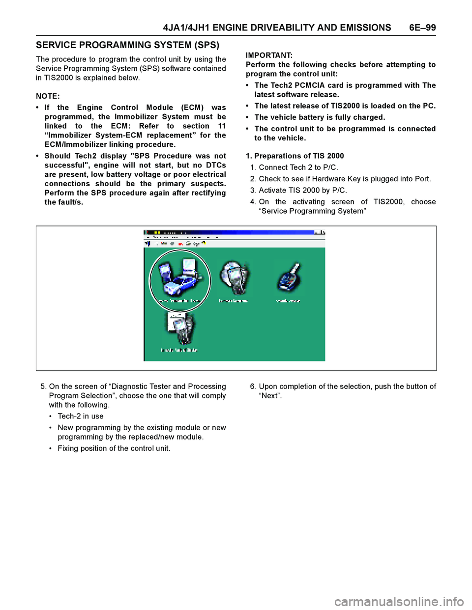
4. On the activating screen of TIS2000, choose
“Service Programming System”
5. On the screen of “Diagnostic Tester and Processing
Program Selection”, choose the one that will comply
with the following.
Tech-2 in use
New programming by the ex isting module or new
programming by the replaced/new module.
Fix ing position of the control unit.6. Upon completion of the selection, push the button of
“Nex t”.
Page 1479 of 4264
4JA1/4JH1 ENGINE DRIVEABILITY AND EMISSIONS 6E–107
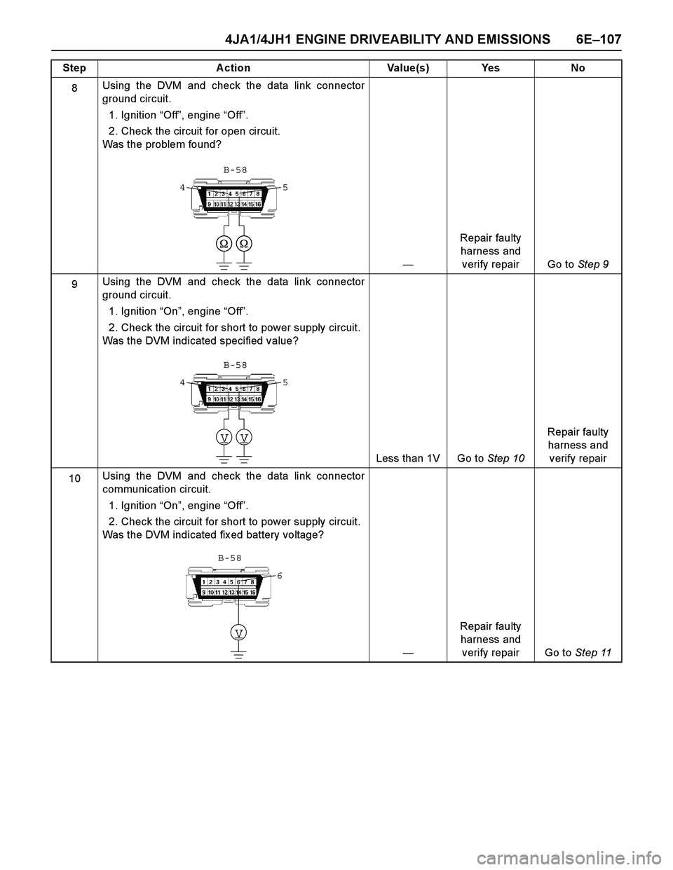
8Using the DVM and check the data link connector
ground circuit.
1. Ignition “Off”, engine “Off”.
2. Check the circuit for open circuit.
Was the problem found?
—Repair faulty
harness and
verify repair Go to Step 9
9Using the DVM and check the data link connector
ground circuit.
1. Ignition “On”, engine “Off”.
2. Check the circuit for short to power supply circuit.
Was the DVM indicated specified value?
Less than 1V Go to Step 10Repair faulty
harness and
verify repair
10Using the DVM and check the data link connector
communication circuit.
1. Ignition “On”, engine “Off”.
2. Check the circuit for short to power supply circuit.
Was the DVM indicated fix ed battery voltage?
—Repair faulty
harness and
verify repair Go to Step 11 Step Action Value(s) Yes No
5 4
B-58
VV
5 4
B-58
V
6
B-58
Page 1481 of 4264
4JA1/4JH1 ENGINE DRIVEABILITY AND EMISSIONS 6E–109
NO CHECK ENGINE LAMP (MIL)
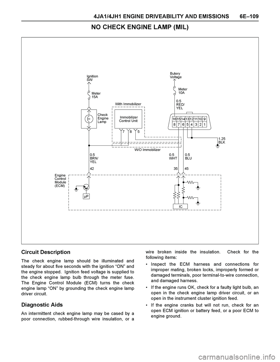
Circuit Description
The check engine lamp should be illuminated and
steady for about five seconds with the ignition “ON” and
the engine stopped. Ignition feed voltage is supplied to
the check engine lamp bulb through the meter fuse.
The Engine Control Module (ECM) turns the check
engine lamp “ON” by grounding the check engine lamp
driver circuit.
Diagnostic Aids
An intermittent check engine lamp may be cased by a
poor connection, rubbed-through wire insulation, or awire broken inside the insulation. Check for the
following items:
Inspect the ECM harness and connections for
improper mating, broken locks, improperly formed or
damaged terminals, poor terminal-to-wire connection,
and damaged harness.
If the engine runs OK, check for a faulty light bulb, an
open in the check engine lamp driver circuit, or an
open in the instrument cluster ignition feed.
If the engine cranks but will not run, check for an
open ECM ignition or battery feed, or a poor ECM to
engine ground.
Page 1486 of 4264
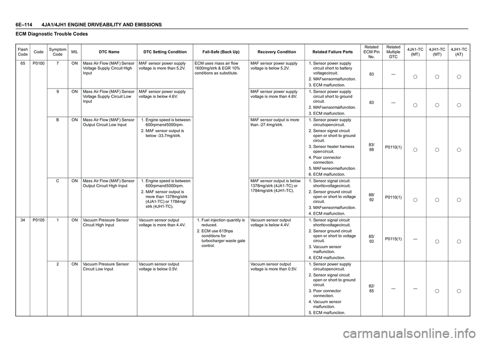
6E–114 4JA1/4JH1 ENGINE DRIVEABILITY AND EMISSIONSECM Diagnostic Trouble CodesFlash
CodeCodeSymptom
CodeMILDTC Name DTC Setting Condition Fail-Safe (Back Up) Recovery Condition Related Failure PartsRelated
ECM Pin
No.Related
Multiple
DTC4JA1-TC
(MT)4JH1-TC
(MT)4JH1-TC
(AT)
65 P0100 7 ON Mass Air Flow (MAF) Sensor
Voltage Supply Circuit High
InputMAF sensor power supply
voltage is more than 5.2V.ECM uses mass air flow
1600mg/strk & EGR 10%
conditions as substitute.MAF sensor power supply
voltage is below 5.2V.1. Sensor power supply
circuit short to battery
voltage circuit.
2. MAF sensor malfunction.
3. ECM malfunction.83 —
9 ON Mass Air Flow (MAF) Sensor
Voltage Supply Circuit Low
InputMAF sensor power supply
voltage is below 4.6V.MAF sensor power supply
voltage is more than 4.6V.1. Sensor power supply
circuit short to ground
c i r c u i t .
2. MAF sensor malfunction.
3. ECM malfunction.83 —
B ON Mass Air Flow (MAF) Sensor
Output Circuit Low Input1. Engine speed is between
600rpm and 5000rpm.
2. MAF sensor output is
below -33.7mg/strk.MAF sensor output is more
than -27.4mg/strk.1. Sensor power supply
circuit open circuit.
2. Sensor signal circuit
open or short to ground
c i r c u i t .
3. Sensor heater harness
o p e n c i r c u i t .
4. Poor connector
c o n n e c t i o n .
5. MAF sensor malfunction.
6. ECM malfunction.8 3 /
88P0110(1)
C ON Mass Air Flow (MAF) Sensor
Output Circuit High Input1. Engine speed is between
600rpm and 5000rpm.
2. MAF sensor output is
more than 1378mg/strk
(4JA1-TC) or 1784mg/
strk (4JH1-TC).MAF sensor output is below
1378mg/strk (4JA1-TC) or
1784mg/strk (4JH1-TC).1. Sensor signal circuit
short to voltage circuit.
2. Sensor ground circuit
open or short to voltage
c i r c u i t .
3. MAF sensor malfunction.
4. ECM malfunction.8 8 /
92P0110(1)
34 P0105 1 ON Vacuum Pressure Sensor
Circuit High InputVacuum sensor output
voltage is more than 4.4V.1. Fuel injection quantity is
r e d u c e d .
2. ECM use 615hpa
conditions for
turbocharger waste gate
control.Vacuum sensor output
voltage is below 4.4V.1. Sensor signal circuit
short to voltage circuit.
2. Sensor ground circuit
open or short to voltage
c i r c u i t .
3. Vacuum sensor
m a l f u n c t i o n .
4. ECM malfunction.8 5 /
93P0115(1) —
2 ON Vacuum Pressure Sensor
Circuit Low InputVacuum sensor output
voltage is below 0.5V.Vacuum sensor output
voltage is more than 0.5V.1. Sensor power supply
circuit open circuit.
2. Sensor signal circuit
open or short to ground
c i r c u i t .
3. Poor connector
c o n n e c t i o n .
4. Vacuum sensor
m a l f u n c t i o n .
5. ECM malfunction.8 2 /
85——
Page 1487 of 4264
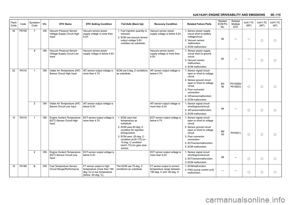
4JA1/4JH1 ENGINE DRIVEABILITY AND EMISSIONS 6E–115
34 P0105 7 ON Vacuum Pressure Sensor
Voltage Supply Circuit High
InputVacuum sensor power
supply voltage is more than
5.2V.1. Fuel injection quantity is
r e d u c e d .
2. ECM use vacuum sensor
output voltage 5.0V
condition as substitute.Vacuum sensor power
supply voltage is below 5.2V.1. Sensor power supply
circuit short to battery
voltage circuit.
2. Vacuum sensor
m a l f u n c t i o n .
3. ECM malfunction.82 — —
9 ON Vacuum Pressure Sensor
Voltage Supply Circuit Low
InputVacuum sensor power
supply voltage is below 4.5V.Vacuum sensor power
supply voltage is more than
4.5V.1. Sensor power supply
circuit short to ground
c i r c u i t .
2. Vacuum sensor
m a l f u n c t i o n .
3. ECM malfunction.82 — —
23 P0110 1 ON Intake Air Temperature (IAT)
Sensor Circuit High InputIAT sensor output voltage is
more than 4.7V.ECM use 0 deg. C conditions
as substitute.IAT sensor output voltage is
below 4.7V.1. Sensor signal circuit
open or short to voltage
c i r c u i t .
2. Sensor ground circuit
open or short to voltage
c i r c u i t .
3. Poor connector
c o n n e c t i o n
4. IAT sensor malfunction.
5. ECM malfunction.8 4 /
92P0100(B)/
P0100(C)
2 ON Intake Air Temperature (IAT)
Sensor Circuit Low InputIAT sensor output voltage is
below 0.3V.IAT sensor output voltage is
more than 0.3V.1. Sensor signal circuit
short to ground circuit.
2. IAT sensor malfunction.
3. ECM malfunction.84 —
14 P0115 1 ON Engine Coolant Temperature
(ECT) Sensor Circuit High
InputECT sensor output voltage is
more than 4.7V.1. ECM uses fuel
temperature as
s u b s t i t u t e .
2. ECM uses 60 deg. C
condition for injection
t i m i n g c o n t r o l .
3. ECM uses -25 deg. C
condition (4JA1-TC) or -
15 deg. C condition
(4JH1-TC) for glow time
control.ECT sensor output voltage is
below 4.7V.1. Sensor signal circuit
open or short to voltage
c i r c u i t .
2. Sensor ground circuit
open or short to voltage
c i r c u i t .
3. Poor connector
c o n n e c t i o n
4. ECT sensor malfunction.
5. ECM malfunction.8 9 /
93P0105(1)
2 ON Engine Coolant Temperature
(ECT) Sensor Circuit Low
InputECT sensor output voltage is
below 0.3V.ECT sensor output voltage is
more than 0.3V.1. Sensor signal circuit
short to ground circuit.
2. ECT sensor malfunction.
3. ECM malfunction.89 —
15 P0180 B ON Fuel Temperature Sensor
Circuit Range/PerformanceFT sensor output is high
temperature (more than 150
deg. C) or low temperature
(below -40 deg. C).The ECM use 75 deg. C
conditions as substitute.FT sensor output is correct
temperature range between
150 deg. C and -40 deg. C.1 . E C M m a l f u n c t i o n .
2. PSG (pump control unit)
malfunction.—— Flash
CodeCodeSymptom
CodeMILDTC Name DTC Setting Condition Fail-Safe (Back Up) Recovery Condition Related Failure PartsRelated
ECM Pin
No.Related
Multiple
DTC4JA1-TC
(MT)4JH1-TC
(MT)4JH1-TC
(AT)
Page 1492 of 4264
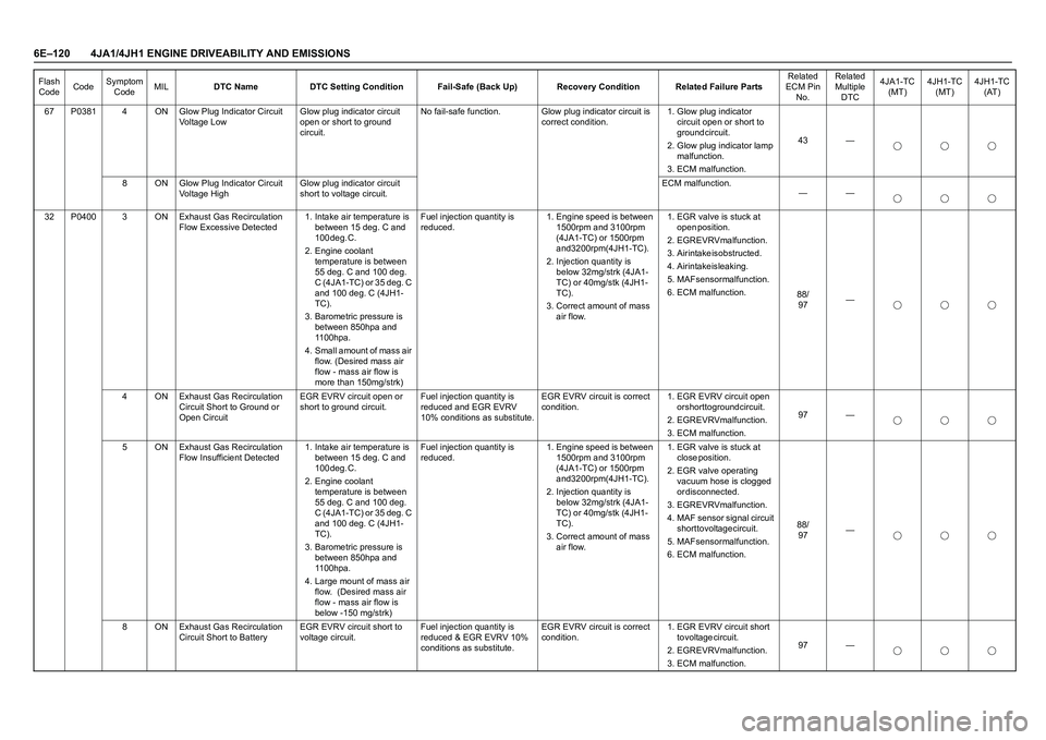
6E–120 4JA1/4JH1 ENGINE DRIVEABILITY AND EMISSIONS
67 P0381 4 ON Glow Plug Indicator Circuit
Voltage LowGlow plug indicator circuit
open or short to ground
circuit.No fail-safe function. Glow plug indicator circuit is
correct condition.1. Glow plug indicator
circuit open or short to
g r o u n d c i r c u i t .
2. Glow plug indicator lamp
m a l f u n c t i o n .
3. ECM malfunction.43 —
8 ON Glow Plug Indicator Circuit
Voltage HighGlow plug indicator circuit
short to voltage circuit.ECM malfunction.
——
32 P0400 3 ON Exhaust Gas Recirculation
Flow Excessive Detected1. Intake air temperature is
between 15 deg. C and
1 0 0 d e g . C .
2. Engine coolant
temperature is between
55 deg. C and 100 deg.
C (4JA1-TC) or 35 deg. C
and 100 deg. C (4JH1-
T C ) .
3. Barometric pressure is
between 850hpa and
1 1 0 0 h p a .
4. Small amount of mass air
flow. (Desired mass air
flow - mass air flow is
more than 150mg/strk)Fuel injection quantity is
reduced. 1. Engine speed is between
1500rpm and 3100rpm
(4JA1-TC) or 1500rpm
and 3200rpm (4JH1-TC).
2. Injection quantity is
below 32mg/strk (4JA1-
TC) or 40mg/stk (4JH1-
T C ) .
3. Correct amount of mass
air flow.1. EGR valve is stuck at
o p e n p o s i t i o n .
2. EGR EVRV malfunction.
3 . A i r i n t a k e i s o b s t r u c t e d .
4. Air intake is leaking.
5. MAF sensor malfunction.
6. ECM malfunction.
8 8 /
97—
4 ON Exhaust Gas Recirculation
Circuit Short to Ground or
Open CircuitEGR EVRV circuit open or
short to ground circuit.Fuel injection quantity is
reduced and EGR EVRV
10% conditions as substitute.EGR EVRV circuit is correct
condition.1. EGR EVRV circuit open
or short to ground circuit.
2. EGR EVRV malfunction.
3. ECM malfunction.97 —
5 ON Exhaust Gas Recirculation
Flow Insufficient Detected1. Intake air temperature is
between 15 deg. C and
100 deg. C.
2. Engine coolant
temperature is between
55 deg. C and 100 deg.
C (4JA1-TC) or 35 deg. C
and 100 deg. C (4JH1-
T C ) .
3. Barometric pressure is
between 850hpa and
1 1 0 0 h p a .
4. Large mount of mass air
flow. (Desired mass air
flow - mass air flow is
below -150 mg/strk)Fuel injection quantity is
reduced. 1. Engine speed is between
1500rpm and 3100rpm
(4JA1-TC) or 1500rpm
and 3200rpm (4JH1-TC).
2. Injection quantity is
below 32mg/strk (4JA1-
TC) or 40mg/stk (4JH1-
T C ) .
3. Correct amount of mass
air flow.1. EGR valve is stuck at
c l o s e p o s i t i o n .
2. EGR valve operating
vacuum hose is clogged
or disconnected.
3. EGR EVRV malfunction.
4. MAF sensor signal circuit
short to voltage circuit.
5. MAF sensor malfunction.
6. ECM malfunction.8 8 /
97—
8 ON Exhaust Gas Recirculation
Circuit Short to BatteryEGR EVRV circuit short to
voltage circuit.Fuel injection quantity is
reduced & EGR EVRV 10%
conditions as substitute.EGR EVRV circuit is correct
condition.1. EGR EVRV circuit short
t o v o l t a g e c i r c u i t .
2. EGR EVRV malfunction.
3. ECM malfunction.97 — Flash
CodeCodeSymptom
CodeMILDTC Name DTC Setting Condition Fail-Safe (Back Up) Recovery Condition Related Failure PartsRelated
ECM Pin
No.Related
Multiple
DTC4JA1-TC
(MT)4JH1-TC
(MT)4JH1-TC
(AT)
Page 1493 of 4264
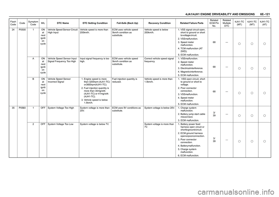
4JA1/4JH1 ENGINE DRIVEABILITY AND EMISSIONS 6E–121
24 P0500 1 ON
at
next
igniti
on
cycleVehicle Speed Sensor Circuit
High InputVehicle speed is more than
200km/h.ECM uses vehicle speed
5km/h condition as
substitute.Vehicle speed is below
200km/h.1. VSS signal circuit open,
short to ground or short
t o v o l t a g e c i r c u i t .
2. VSS malfunction.
3. Speed meter
m a l f u n c t i o n .
4. TCM malfunction (AT
2 W D ) .
5. ECM malfunction.68 —
A O N
at
next
igniti
on
cycleVehicle Speed Sensor Input
Signal Frequency Too HighInput signal frequency is too
high.ECM uses vehicle speed
5km/h condition as
substitute.Correct vehicle speed signal
frequency. 1. VSS malfunction.
2. Speed meter
m a l f u n c t i o n .
3. Electrical interference.
4. Magnetic interference.
5. ECM malfunction.68 —
B O N
at
next
igniti
on
cycleVehicle Speed Sensor
Incorrect Signal1. Engine speed is more
than 3200rpm (4JA1-TC)
or 3600rpm (4JH1-TC).
2. Fuel injection quantity is
more than 30mg/strk
(4JA1-TC) or 41mg/strk
( 4 J H 1 - T C ) .
3. Vehicle speed is below
1.5km/h.Fuel injection quantity is
reduced.Vehicle speed is more than
1.5km/h.1. VSS open circuit, short
to ground or short to
voltage.
2. Poor connector
c o n n e c t i o n .
3. VSS malfunction.
4. Speed meter
m a l f u n c t i o n .
5. ECM malfunction.68 —
35 P0560 1 OFF System Voltage Too High System voltage is more than
20V.ECM uses 9V conditions as
substitute.System voltage is below 20V. 1. Charge system
m a l f u n c t i o n .
2. Battery jump start cable
misconnect.
3. ECM malfunction.3 /
39—
2 OFF System Voltage Too Low System voltage is below 7V. System voltage is more than
7V.1. Battery power feed
harness open circuit or
short to ground circuit.
2. ECM ground harness
open or poor connection.
3. Poor connector
c o n n e c t i o n .
4 . B a t t e r y m a l f u n c t i o n .
5. Charge system
m a l f u n c t i o n .
6. ECM malfunction.3 /
39— Flash
CodeCodeSymptom
CodeMILDTC Name DTC Setting Condition Fail-Safe (Back Up) Recovery Condition Related Failure PartsRelated
ECM Pin
No.Related
Multiple
DTC4JA1-TC
(MT)4JH1-TC
(MT)4JH1-TC
(AT)