Page 1123 of 4264

TROUBLESHOOTING 6 – 3
1. Hard Starting
Inspect the following items before diagnosis.
1. The battery conditions.
The terminal connection condition.
The battery charge condition or battery power weakness.
2. The fan belt loosen or broken.
3. The main fuse condition (open or not).
4. Fuel quantity level.
1–1 Starter motor inoperative
Step Action Value(s) Yes No
1 Check the starter switch.
Does the starter switch work? —
Go to Step 2 Repair or
replace the
starter switch
2 Check the starter relay.
Does the starter relay work? —
Go to Step 3 Repair or
replace the
starter relay
3 Check the magnetic switch.
Does the magnetic switch work? —
Go to Step 4 Repair or
replace the
magnetic
switch
4 Check the pinion gear condition on the starter motor.
Was the condition normal? —
Go to Step 5 Replace the
pinion gear
5 Check the brush wear or brush spring weakness.
Was the condition normal? —
Replace the
starter motor
assembly Repair or
replace the
brush or brush
spring
1-2 Starter motor operates but engine does not turn over
Step Action Value(s) Yes No
1 Check the engine internal seizure.
Was the engine seized? —
Repair or
replace seized
parts Check other
DTC by Tech
2 and go to
indicated DTC
Page 1136 of 4264

6 – 16 TROUBLESHOOTING
14. Battery Charging and Noise Problem
Visual/physical check the following items before diagnosis.
The drive belt tension.
The battery terminals connection condition.
The ground connection condition.
The generator and the battery fastener condition.
The battery fluid level and specific gravity.
14-1 Battery No Charging
Step Action Value(s) Yes No
1 Was “Visual/Physical Check" performed.
—
Go to Step 2 Go to
visual/physical
check
2 Inspect the brush contact condition on the generator.
Was there poor contact between the brush and the
slip ring? — Repair or
replace the
brush and/or
the slip ring. Go to Step 3
3 Inspect the stator coil on the generator.
Was there an open circuit or the scorching on the
stator coil? —
Replace the
stator coil. Go to Step 4
4 Inspect the rotor coil on the generator.
Was there an open circuit or the scorching on the
rotor coil? —
Replace the
rotor coil. Go to Step 5
5 Inspect the rectifier on the generator.
Was the rectifier defective? — Replace the
rectifier Go to Step 6
6 Inspect the IC regulator.
Was the IC regulator defective? — Replace the IC
regulator. Go to Step 7
7 Are any DTC stored? — Go to indicated
DTC. Solved
14-2 Battery Overcharging
Step Action Value(s) Yes No
1 Was “Visual/Physical Check" performed.
—
Go to Step 2 Go to
visual/physical
check
2 Inspect the terminal circuit.
Were the B and F terminals shorted? — Repair the
short circuit. Go to Step 3
3 Check the regulating voltage.
Was the IC regulator voltage excessive? — Replace the IC
regulator. Go to Step 4
4 Are any DTC stored? — Go to indicated
DTC. Solved
Page 1137 of 4264
 Yes No
1 Was “Visual/Physical Check\" performed.
—
Go to Step 2 Go to
visual/physical
check
2 Inspect the brush")
TROUBLESHOOTING 6 – 17
14-3 Battery Under Charging
Step Action Value(s) Yes No
1 Was “Visual/Physical Check" performed.
—
Go to Step 2 Go to
visual/physical
check
2 Inspect the brush contact condition on the generator.
Was there intermittent contact between the brush
and the slip ring? — Repair or
replace the
brush holder
assembly. Go to Step 3
3 Inspect the rotor coil on the generator.
Was there a short circuit in the rotor coil? — Repair or
replace the
rotor coil. Go to Step 4
4 Inspect the stator coil on the generator.
Was there an open circuit or the short circuit on the
stator coil? — Repair or
replace the
stator coil. Go to Step 5
5 Inspect the rectifier on the generator.
Was the rectifier defective? — Replace the
rectifier Go to Step 6
6 Inspect the IC regulator on the generator.
Was the IC regulator defective? — Replace the IC
regulator. Go to Step 7
7 Was the electrical load excessive? — Replace more
higher capacity
generator. Go to Step 8
8 Are any DTC stored? — Go to indicated
DTC. Solved
14-4 Battery Unstable Charging Current
Step Action Value(s) Yes No
1 Was “Visual/Physical Check" performed.
—
Go to Step 2 Go to
visual/physical
check
2 Inspect the brush contact condition on the generator.
Was there poor contact between the brush and the
slip ring? — Repair or
replace the
brush and/or
the slip ring. Go to Step 3
3 Inspect the rotor coil on the generator.
Was there the short circuit or an open circuit in the
rotor coil? — Repair or
replace the
rotor coil. Go to Step 4
4 Inspect the stator coil on the generator.
Was there an open circuit or the short circuit in the
stator coil? — Repair or
replace the
stator coil. Go to Step 5
5 Inspect the connection between the rectifier and
stator coil on the generator.
Was there a loose connection between the rectifier
and stator coil ? —
Repair the
loose
connection. Go to Step 6
6 Inspect the IC regulator on the generator.
Was the IC regulator defective? — Replace the IC
regulator. Go to Step 7
7 Are any DTC stored? — Go to indicated
DTC. Solved
Page 1139 of 4264

TROUBLESHOOTING 6 – 19
15. Starter Motor Problem
Visual/physical check the following items before diagnosis.
The battery terminals connection condition.
The ground connection condition.
The starter motor or the battery fastener condition.
The battery fluid level and specific gravity.
15-1 Starter motor pinion engages to ring gear but engine does not turn over
Step Action Value(s) Yes No
1 Was “Visual/Physical Check" performed.
—
Go to Step 2 Go to
visual/physical
check
2 Check the contact condition between the brush and
the commutator.
Was the brush and the commutator contact
intermittent? — Replace the
brush or repair
the
commutator. Go to Step 3
3 Were the brush and the commutator contact faces
dirty?
—
Clean contact
face Go to Step 4
4 Was the pinion clutch slipped? — Replace the
pinion clutch Go to Step 5
5 Inspect the armature field coil.
Was there an open circuit or a short circuit in the
armature field coil? — Repair or
replace the
armature field
coil. Go to Step 6
6 Are any DTC stored? — Go to indicated
DTC. Solved
15-2 Incorrect pinion and ring gear engagement
Step Action Value(s) Yes No
1 Was “Visual/Physical Check" performed.
—
Go to Step 2 Go to
visual/physical
check
2 Inspect the pinion and the ring gear teeth.
Were the pinion and/or the ring gear teeth worn or
broken? —
Replace the
wron parts. Go to Step 3
3 Inspect the pinion gear return movement.
Was the pinion gear return movement incorrect? — Adjust or
replace the
movement
parts. Go to Step 4
4 Are any DTC stored? — Go to indicated
DTC. Solved
Page 1145 of 4264
ENGINE MECHANICAL 6A – 5
Engine model
Item 4JA1T (L) 4JA1TC
Oil pump type
Oil filter type
Oil capacity lit (US/UK gal)
Oil cooler type Gear
Cartridge paper element
6.2 (1.64/1.36)
Water cooled
Cooling system
Water pump type Centrifugal
Thermostat type Wax pellet with jiggle valve
Air cleaner type Dry paper element Viscous paper element
Battery type/voltage � No. of units 80D26L � 1
95D31L � 1 (OPT)
Generator capacity V-A 12 – 60
12 – 80
Starter motor output V-Kw 12 – 2.3
Turbocharger model
Turbine type
Compressor type *IHI RHF 4H
Mixed flow type
Backward & rake
*IHI : Ishikawajima-Harima Heavy Industries., Ltd.
Page 1147 of 4264
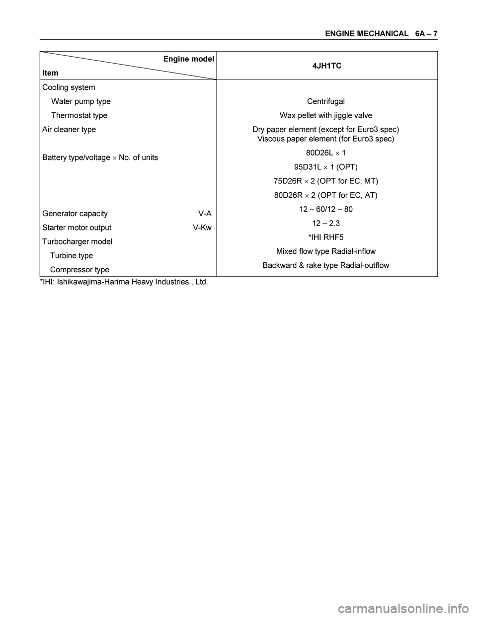
ENGINE MECHANICAL 6A – 7
Engine model
Item 4JH1TC
Cooling system
Water pump type
Thermostat type
Air cleaner type
Battery type/voltage � No. of units
Generator capacity V-A
Starter motor output V-Kw
Turbocharger model
Turbine type
Compressor type
Centrifugal
Wax pellet with jiggle valve
Dry paper element (except for Euro3 spec)
Viscous paper element (for Euro3 spec)
80D26L � 1
95D31L � 1 (OPT)
75D26R � 2 (OPT for EC, MT)
80D26R � 2 (OPT for EC, AT)
12 – 60/12 – 80
12 – 2.3
*IHI RHF5
Mixed flow type Radial-inflow
Backward & rake type Radial-outflow
*IHI: Ishikawajima-Harima Heavy Industries., Ltd.
Page 1177 of 4264

ENGINE MECHANICAL 6A – 37
REMOVAL AND INSTALLATION
Read this section carefully before performing any removal and installation procedure. This section gives
you important points as well as the order of operation. Be sure that you understand everything in this section before
you begin.
Removal
P1010011
1. Battery
1) Disconnect the battery cable and the grounding cable from the battery terminals.
2) Remove the battery clamp. Take care not to accidentally short the battery with the wrench or some
other tool.
3) Remove the battery.
4) Disconnect the battery cable at the starter motor and the ground cable at the cylinder body.
2. Engine Hood Apply setting marks to the engine hood and the engine
hood hinges before removing the engine hood. This will
facilitate reinstallation of the engine hood to its original
position.
3. Supporting the Vehicle 1) Jack up the vehicle.
2) Place chassis stands at the front and the rear of the vehicle.
4. Under cover (for 4x4 model) 5. Rear propeller shaft 1) Remove the propeller shaft flange yoke at the rear differential.
2) Remove the center bearing retainer bolts.
3) Remove the propeller shaft together with the center bearing from the transmission mainshaft spline.
F06R300006 P1010002
Page 1296 of 4264
6B – 16 ENGINE COOLING
P1010064
Removal
1. Disconnect battery ground cable.
2. Loosen a drain plug to drain EC.
3. Disconnect oil cooler hose on automatic transmission (A/T).
4. Disconnect radiator inlet hose and outlet hose from the engine.
PTW46BSH000101
5. Remove fan guide(1), clips(2) on both sides and the bottom
lock, then remove lower fan guide(3) with fan shroud(4).
6. Disconnect the reserve tank hose(6) from radiator.
RTW36BMH000101
7. Remove bracket(5).
8. Lift up and remove the radiator assembly with hose, taking
care not to damage the radiator core with a fan blade.
 4JA1TC
Oil pump type
Oil filter type
Oil capacity lit (US/UK gal)
Oil cooler type Gear
Cartridge paper element
6.2 (1.64/1.36")
.
4. Discon")