Page 1641 of 3371
EC-450Revision: August 2007
DTC P1273, P1283 A/F SENSOR 1
2004 QX56
Specification data are reference values and are measured between each terminal and ground.
CAUTION:
Do not use ECM ground terminals when measuring input/output voltage. Doing so may result in dam-
age to the ECM's transistor. Use a ground other than ECM terminals, such as the ground.
Diagnostic ProcedureUBS00H9Y
1. CHECK GROUND CONNECTIONS
1. Turn ignition switch OFF.
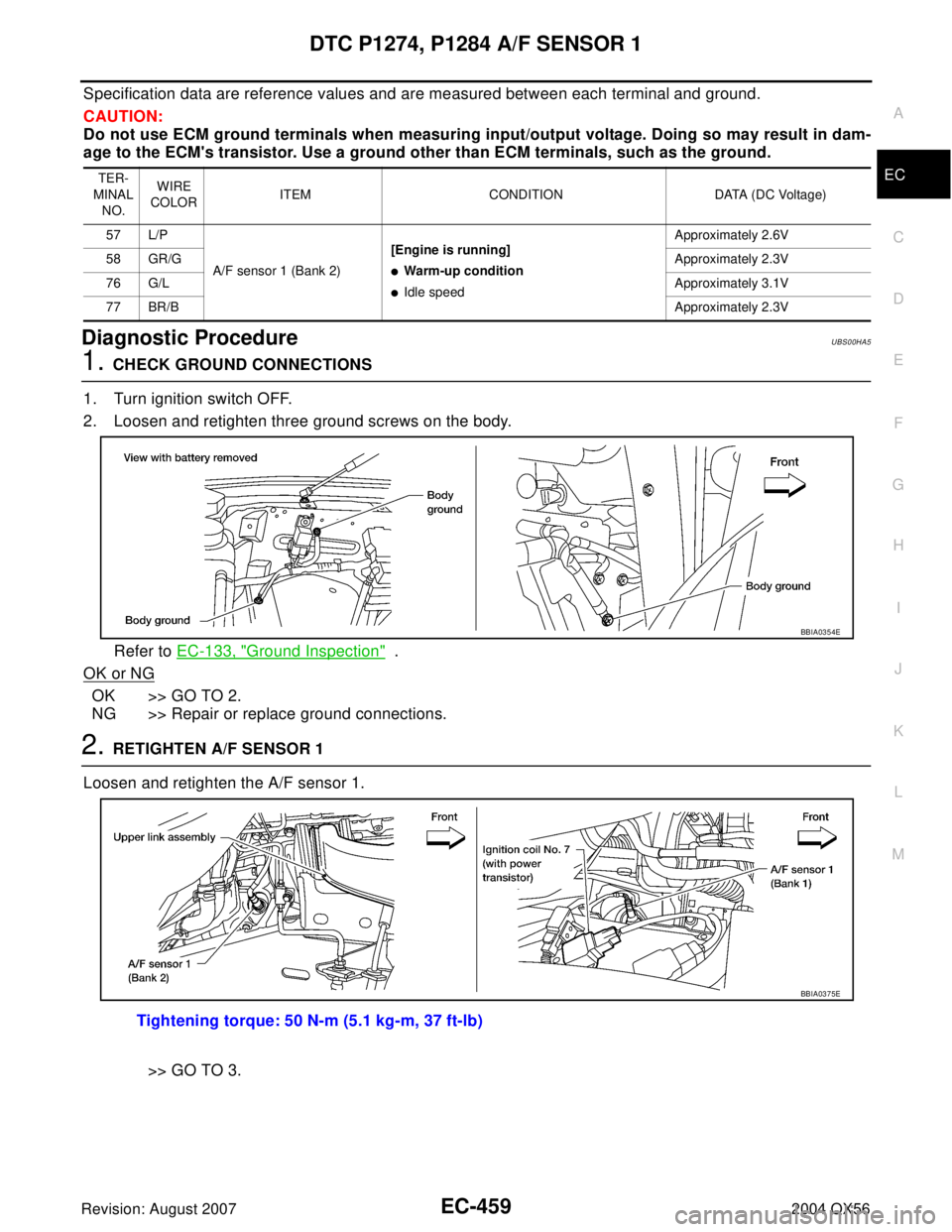
2. Loosen and retighten three ground screws on the body.
Refer to EC-133, "
Ground Inspection" .
OK or NG
OK >> GO TO 2.
NG >> Repair or replace ground connections.
2. RETIGHTEN A/F SENSOR 1
Loosen and retighten the A/F sensor 1.
>> GO TO 3.
TER-
MINAL
NO.WIRE
COLORITEM CONDITION DATA (DC Voltage)
57 L/P
A/F sensor 1 (Bank 2)[Engine is running]
�Warm-up condition
�Idle speedApproximately 2.6V
58 GR/GApproximately 2.3V
76 G/LApproximately 3.1V
77 BR/BApproximately 2.3V
BBIA0354E
Tightening torque: 50 N-m (5.1 kg-m, 37 ft-lb)
BBIA0375E
Page 1650 of 3371

DTC P1274, P1284 A/F SENSOR 1
EC-459
C
D
E
F
G
H
I
J
K
L
MA
EC
Revision: August 20072004 QX56
Specification data are reference values and are measured between each terminal and ground.
CAUTION:
Do not use ECM ground terminals when measuring input/output voltage. Doing so may result in dam-
age to the ECM's transistor. Use a ground other than ECM terminals, such as the ground.
Diagnostic ProcedureUBS00HA5
1. CHECK GROUND CONNECTIONS
1. Turn ignition switch OFF.
2. Loosen and retighten three ground screws on the body.
Refer to EC-133, "
Ground Inspection" .
OK or NG
OK >> GO TO 2.
NG >> Repair or replace ground connections.
2. RETIGHTEN A/F SENSOR 1
Loosen and retighten the A/F sensor 1.
>> GO TO 3.
TER-
MINAL
NO.WIRE
COLORITEM CONDITION DATA (DC Voltage)
57 L/P
A/F sensor 1 (Bank 2)[Engine is running]
�Warm-up condition
�Idle speedApproximately 2.6V
58 GR/GApproximately 2.3V
76 G/LApproximately 3.1V
77 BR/BApproximately 2.3V
BBIA0354E
Tightening torque: 50 N-m (5.1 kg-m, 37 ft-lb)
BBIA0375E
Page 1660 of 3371
DTC P1276, P1286 A/F SENSOR 1
EC-469
C
D
E
F
G
H
I
J
K
L
MA
EC
Revision: August 20072004 QX56
Specification data are reference values and are measured between each terminal and ground.
CAUTION:
Do not use ECM ground terminals when measuring input/output voltage. Doing so may result in dam-
age to the ECM's transistor. Use a ground other than ECM terminals, such as the ground.
Diagnostic ProcedureUBS00HAD
1. CHECK GROUND CONNECTIONS
1. Turn ignition switch OFF.
2. Loosen and retighten three ground screws on the body.
Refer to EC-133, "
Ground Inspection" .
OK or NG
OK >> GO TO 2.
NG >> Repair or replace ground connections.
TER-
MINAL
NO.WIRE
COLORITEM CONDITION DATA (DC Voltage)
57 L/P
A/F sensor 1 (Bank 2)[Engine is running]
�Warm-up condition
�Idle speedApproximately 2.6V
58 GR/GApproximately 2.3V
76 G/LApproximately 3.1V
77 BR/BApproximately 2.3V
BBIA0354E
Page 1669 of 3371
EC-478Revision: August 2007
DTC P1278, P1288 A/F SENSOR 1
2004 QX56
Specification data are reference values and are measured between each terminal and ground.
CAUTION:
Do not use ECM ground terminals when measuring input/output voltage. Doing so may result in dam-
age to the ECM's transistor. Use a ground other than ECM terminals, such as the ground.
Diagnostic ProcedureUBS00HAK
1. CHECK GROUND CONNECTIONS
1. Turn ignition switch OFF.
2. Loosen and retighten three ground screws on the body.
Refer to EC-133, "
Ground Inspection" .
OK or NG
OK >> GO TO 2.
NG >> Repair or replace ground connections.
2. RETIGHTEN A/F SENSOR 1
Loosen and retighten the A/F sensor 1.
>> GO TO 3.
TER-
MINAL
NO.WIRE
COLORITEM CONDITION DATA (DC Voltage)
57 L/P
A/F sensor 1 (Bank 2)[Engine is running]
�Warm-up condition
�Idle speedApproximately 2.6V
58 GR/GApproximately 2.3V
76 G/LApproximately 3.1V
77 BR/BApproximately 2.3V
BBIA0354E
Tightening torque: 50 N-m (5.1 kg-m, 37 ft-lb)
BBIA0375E
Page 1681 of 3371
EC-490Revision: August 2007
DTC P1279, P1289 A/F SENSOR 1
2004 QX56
Specification data are reference values and are measured between each terminal and ground.
CAUTION:
Do not use ECM ground terminals when measuring input/output voltage. Doing so may result in dam-
age to the ECM's transistor. Use a ground other than ECM terminals, such as the ground.
Diagnostic ProcedureUBS00HAR
1. CHECK GROUND CONNECTIONS
1. Turn ignition switch OFF.
2. Loosen and retighten three ground screws on the body.
Refer to EC-133, "
Ground Inspection" .
OK or NG
OK >> GO TO 2.
NG >> Repair or replace ground connections.
2. RETIGHTEN A/F SENSOR 1
Loosen and retighten the A/F sensor 1.
>> GO TO 3.
TER-
MINAL
NO.WIRE
COLORITEM CONDITION DATA (DC Voltage)
57 L/P
A/F sensor 1 (Bank 2)[Engine is running]
�Warm-up condition
�Idle speedApproximately 2.6V
58 GR/GApproximately 2.3V
76 G/LApproximately 3.1V
77 BR/BApproximately 2.3V
BBIA0354E
Tightening torque: 50 N-m (5.1 kg-m, 37 ft-lb)
BBIA0375E
Page 1750 of 3371

DTC P2122, P2123 APP SENSOR
EC-559
C
D
E
F
G
H
I
J
K
L
MA
EC
Revision: August 20072004 QX56
Specification data are reference values and are measured between each terminal and ground.
CAUTION:
Do not use ECM ground terminals when measuring input/output voltage. Doing so may result in dam-
age to the ECM's transistor. Use a ground other than ECM terminals, such as the ground.
Diagnostic ProcedureUBS00HC9
1. CHECK GROUND CONNECTIONS
1. Turn ignition switch OFF.
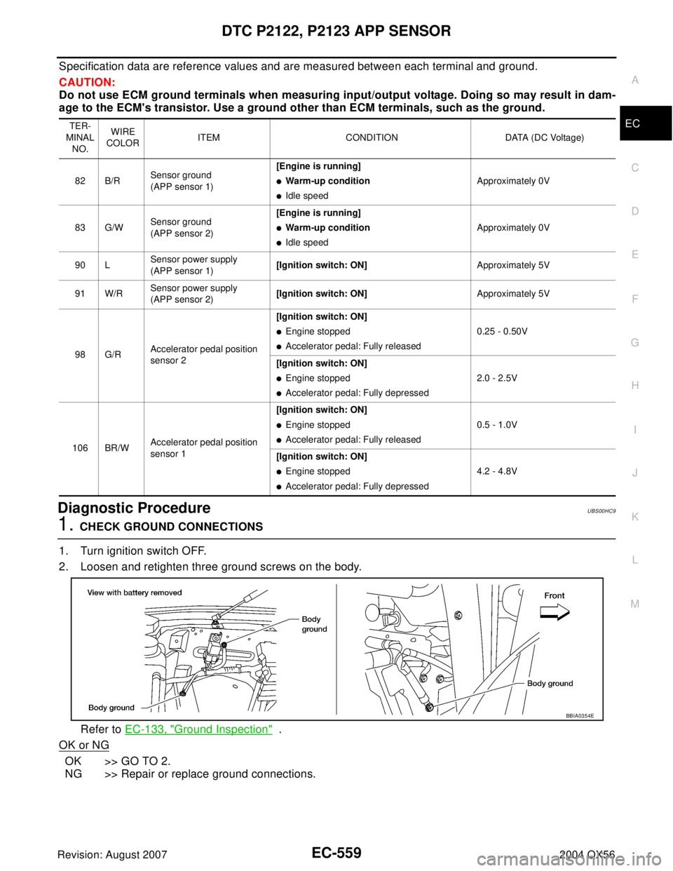
2. Loosen and retighten three ground screws on the body.
Refer to EC-133, "
Ground Inspection" .
OK or NG
OK >> GO TO 2.
NG >> Repair or replace ground connections.
TER-
MINAL
NO.WIRE
COLORITEM CONDITION DATA (DC Voltage)
82 B/RSensor ground
(APP sensor 1)[Engine is running]
�Warm-up condition
�Idle speedApproximately 0V
83 G/WSensor ground
(APP sensor 2)[Engine is running]
�Warm-up condition
�Idle speedApproximately 0V
90 LSensor power supply
(APP sensor 1)[Ignition switch: ON]Approximately 5V
91 W/RSensor power supply
(APP sensor 2)[Ignition switch: ON]Approximately 5V
98 G/RAccelerator pedal position
sensor 2[Ignition switch: ON]
�Engine stopped
�Accelerator pedal: Fully released0.25 - 0.50V
[Ignition switch: ON]
�Engine stopped
�Accelerator pedal: Fully depressed2.0 - 2.5V
106 BR/WAccelerator pedal position
sensor 1[Ignition switch: ON]
�Engine stopped
�Accelerator pedal: Fully released0.5 - 1.0V
[Ignition switch: ON]
�Engine stopped
�Accelerator pedal: Fully depressed4.2 - 4.8V
BBIA0354E
Page 1756 of 3371

DTC P2127, P2128 APP SENSOR
EC-565
C
D
E
F
G
H
I
J
K
L
MA
EC
Revision: August 20072004 QX56
Specification data are reference values and are measured between each terminal and ground.
CAUTION:
Do not use ECM ground terminals when measuring input/output voltage. Doing so may result in dam-
age to the ECM's transistor. Use a ground other than ECM terminals, such as the ground.
Diagnostic ProcedureUBS00HCH
1. CHECK GROUND CONNECTIONS
1. Turn ignition switch OFF.
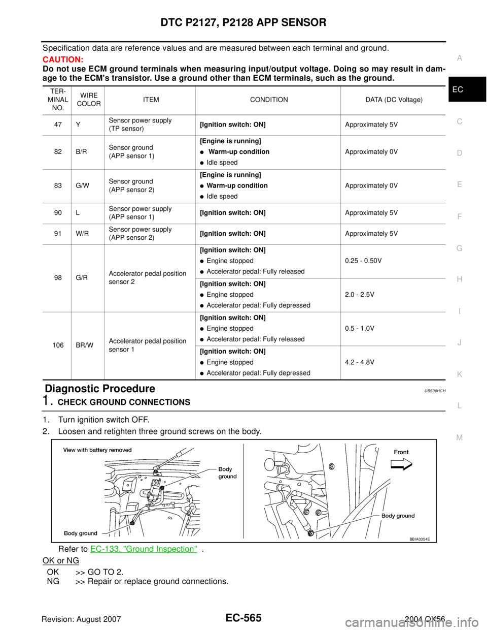
2. Loosen and retighten three ground screws on the body.
Refer to EC-133, "
Ground Inspection" .
OK or NG
OK >> GO TO 2.
NG >> Repair or replace ground connections.
TER-
MINAL
NO.WIRE
COLORITEM CONDITION DATA (DC Voltage)
47 YSensor power supply
(TP sensor)[Ignition switch: ON]Approximately 5V
82 B/RSensor ground
(APP sensor 1)[Engine is running]
� Warm-up condition
�Idle speedApproximately 0V
83 G/WSensor ground
(APP sensor 2)[Engine is running]
�Warm-up condition
�Idle speed Approximately 0V
90 LSensor power supply
(APP sensor 1)[Ignition switch: ON]Approximately 5V
91 W/RSensor power supply
(APP sensor 2)[Ignition switch: ON]Approximately 5V
98 G/RAccelerator pedal position
sensor 2[Ignition switch: ON]
�Engine stopped
�Accelerator pedal: Fully released0.25 - 0.50V
[Ignition switch: ON]
�Engine stopped
�Accelerator pedal: Fully depressed2.0 - 2.5V
106 BR/WAccelerator pedal position
sensor 1[Ignition switch: ON]
�Engine stopped
�Accelerator pedal: Fully released0.5 - 1.0V
[Ignition switch: ON]
�Engine stopped
�Accelerator pedal: Fully depressed4.2 - 4.8V
BBIA0354E
Page 1763 of 3371

EC-572Revision: August 2007
DTC P2135 TP SENSOR
2004 QX56
Specification data are reference values and are measured between each terminal and ground.
CAUTION:
Do not use ECM ground terminals when measuring input/output voltage. Doing so may result in dam-
age to the ECM's transistor. Use a ground other than ECM terminals, such as the ground.
Diagnostic ProcedureUBS00HCP
1. CHECK GROUND CONNECTIONS
1. Turn ignition switch OFF.
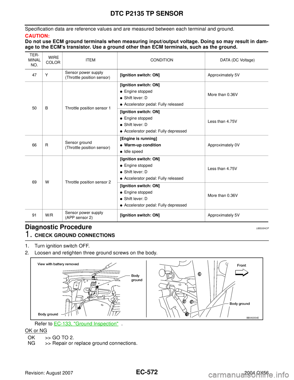
2. Loosen and retighten three ground screws on the body.
Refer to EC-133, "
Ground Inspection" .
OK or NG
OK >> GO TO 2.
NG >> Repair or replace ground connections.
TER-
MINAL
NO. WIRE
COLORITEM CONDITION DATA (DC Voltage)
47 YSensor power supply
(Throttle position sensor)[Ignition switch: ON]Approximately 5V
50 B Throttle position sensor 1[Ignition switch: ON]
�Engine stopped
�Shift lever: D
�Accelerator pedal: Fully releasedMore than 0.36V
[Ignition switch: ON]
�Engine stopped
�Shift lever: D
�Accelerator pedal: Fully depressedLess than 4.75V
66 RSensor ground
(Throttle position sensor)[Engine is running]
�Warm-up condition
�Idle speedApproximately 0V
69 W Throttle position sensor 2[Ignition switch: ON]
�Engine stopped
�Shift lever: D
�Accelerator pedal: Fully releasedLess than 4.75V
[Ignition switch: ON]
�Engine stopped
�Shift lever: D
�Accelerator pedal: Fully depressedMore than 0.36V
91 W/RSensor power supply
(APP sensor 2)[Ignition switch: ON]Approximately 5V
BBIA0354E