Page 2055 of 3371

FL-10Revision: August 2007
FUEL TANK
2004 QX56
REMOVAL
WAR NIN G:
Follow the “General Precautions” before working on the fuel system. Refer to FL-3, "
General Precau-
tions" .
1. Drain the fuel from the fuel tank, if necessary.
�Position the vehicle so it is level.
2. Remove the fuel filler cap to release the pressure from inside the fuel tank.
3. Check the fuel level on level gauge. If the fuel gauge indicates
more than the level as shown (full or almost full), drain the fuel
from the fuel tank until the fuel gauge indicates the level as
shown, or less.
�If the fuel pump does not operate, use the following procedure
to drain the fuel to the specified level after disconnecting the
fuel filler hose from the fuel filler pipe.
a. Insert a suitable hose of less than 15 mm (0.59 in) diameter into
the fuel filler pipe through the fuel filler opening to drain the fuel
from fuel filler pipe.
b. Insert a suitable hose into the fuel tank through the fuel filler
hose to drain the fuel from the fuel tank.
�As a guide, the fuel level reaches the fuel gauge position as shown, or less, when approximately 14
liters (3 3/4 US gal, 3 1/8 Imp gal) of fuel are drained from the fuel tank.
4. Remove the LH rear wheel and tire. Refer to WT-6, "
Rotation" .
5. Remove the four clips and remove the rear fender protector, front.
6. Disconnect the fuel filler hose from the fuel filler pipe and dis-
connect the vent hose quick connector.
7. Release the fuel pressure from the fuel lines. Refer to EC-46, "
FUEL PRESSURE RELEASE" .
8. Remove the second row LH rear seat and the third row rear seat. Refer to SE-103, "
REAR SEAT" .
9. Remove the second and third row rear seat belt buckles mounted on the floor. Refer to SB-3, "
SEAT
BELTS" .
10. Remove the LH center pillar trim, the LH rear trim panel, and the LH rear side door kick plate and weather
stripping. Refer to EI-34, "
BODY SIDE TRIM" .
11. Remove the second row rear center console and base. Refer to EI-36, "
FLOOR TRIM" .
12. Reposition the floor carpet out of the way to access the inspection hole cover, located under the center LH
rear seat.
10. Fuel filler hose 11. Fuel filler pipe 12. Fuel filler cup
13. Fuel filler hose grommet 14. Fuel filler cap 15. Fuel tank shield
WBIA0390E
LBIA0386E
Page 2076 of 3371
 of each comp")
KNUCKLE
FSU-17
C
D
F
G
H
I
J
K
L
MA
B
FSU
Revision: August 20072004 QX56
KNUCKLEPFP:40014
On-Vehicle Inspection and ServiceEES0010R
Make sure the mounting conditions (looseness, backlash) of each component and component status (wear,
damage) are within specifications. Refer to FSU-21, "
Ball Joint" .
Removal and InstallationEES0010S
REMOVAL
1. Remove wheel and tire from vehicle using power tool.
2. Without disconnecting the hydraulic lines, remove brake caliper using power tool. Reposition it aside with
wire. Refer to BR-22, "
Removal and Installation of Brake Caliper and Disc Rotor" .
CAUTION:
It is not necessary to remove bolts on torque member and brake hose except for disassembly or
replacement of caliper assembly. In this case, hang cylinder body with a wire so that the brake
hose in not under tension.
NOTE:
Avoid depressing brake pedal while brake caliper is removed.
3. Put alignment marks on disc rotor and wheel hub and bearing
assembly, then remove disc rotor.
4. Remove ABS sensor from steering knuckle. Refer to BRC-64, "
Removal and Installation" .
CAUTION:
Do not pull on ABS sensor harness.
5. Remove cotter pin, then remove lock nut from drive shaft using power tool.
6. Remove steering outer socket cotter pin at steering knuckle, then loosen mounting nut using power tool.
1. Disc rotor 2. Wheel hub and bearing assembly 3. Wheel stud
4. Splash guard 5. Steering knuckle
WDIA0043E
WDIA0044E
Page 2091 of 3371
 and contain tightening torques,
lubrication points, secti")
GI-10
HOW TO USE THIS MANUAL
Revision: August 20072004 QX56
ComponentsEAS001QX
�THE LARGE ILLUSTRATIONS are exploded views (see the following) and contain tightening torques,
lubrication points, section number of the PA R T S C ATA L O G (e.g. SEC. 440) and other information neces-
sary to perform repairs.
The illustrations should be used in reference to service matters only. When ordering parts, refer to the
appropriate PA R T S C ATA L O G .
Components shown in an illustration may be identified by a circled number. When this style of illustration
is used, the text description of the components will follow the illustration.
SYMBOLS
1. Union bolt 2. Copper washer 3. Brake hose
4. Cap 5. Bleed valve 6. Sliding pin bolt
7. Piston seal 8. Piston 9. Piston boot
10. Cylinder body 11. Sliding pin 12. Torque member mounting bolt
13. Washer 14. Sliding pin boot 15. Bushing
16. Torque member 17. Inner shim cover 18. Inner shim
19. Inner pad 20. Pad retainer 21. Pad wear sensor
22. Outer pad 23. Outer shim 24. Outer shim cover
1: PBC (Poly Butyl Cuprysil) grease
or silicone-based grease2: Rubber grease : Brake fluid
Refer to GI section for additional symbol definitions.
SFIA2959E
SAIA0749E
Page 2098 of 3371

HOW TO USE THIS MANUAL
GI-17
C
D
E
F
G
H
I
J
K
L
MB
GI
Revision: August 20072004 QX56
Optional Splice
DESCRIPTION
SG I9 42
Num-
berItem Description
1 Power condition
�This shows the condition when the system receives battery positive voltage (can be oper-
ated).
2 Fusible link
�The double line shows that this is a fusible link.
�The open circle shows current flow in, and the shaded circle shows current flow out.
3Fusible link/fuse loca-
tion
�This shows the location of the fusible link or fuse in the fusible link or fuse box. For arrange-
ment, refer to PG section, POWER SUPPLY ROUTING.
4Fuse
�The single line shows that this is a fuse.
�The open circle shows current flow in, and the shaded circle shows current flow out.
5 Current rating
�This shows the current rating of the fusible link or fuse.
6 Connectors
�This shows that connector E3 is female and connector M1 is male.
�The G/R wire is located in the 1A terminal of both connectors.
�Terminal number with an alphabet (1A, 5B, etc.) indicates that the connector is SMJ connec-
tor. Refer to PG section, SMJ (SUPER MULTIPLE JUNCTION).
7 Optional splice
�The open circle shows that the splice is optional depending on vehicle application.
8 Splice
�The shaded circle shows that the splice is always on the vehicle.
9 Page crossing
�This arrow shows that the circuit continues to an adjacent page.
�The A will match with the A on the preceding or next page.
10 Common connector
�The dotted lines between terminals show that these terminals are part of the same connector.
11 Option abbreviation
�This shows that the circuit is optional depending on vehicle application.
12 Relay
�This shows an internal representation of the relay. For details, refer to PG section, STAN-
DARDIZED RELAY.
13 Connectors
�This shows that the connector is connected to the body or a terminal with bolt or nut.
Page 2115 of 3371

GI-34
SERVICE INFORMATION FOR ELECTRICAL INCIDENT
Revision: August 20072004 QX56
Control Unit Circuit Test
System Description:When the switch is ON, the control unit lights up the lamp.
INPUT-OUTPUT VOLTAGE CHART
The voltage value is based on the body ground.
*:If high resistance exists in the switch side circuit (caused by a single strand), terminal 1 does not detect battery voltage. Control unit
does not detect the switch is ON even if the switch does not turn ON. Therefore, the control unit does not supply power to light up the
lamp.
INPUT-OUTPUT VOLTAGE CHART
The voltage value is based on the body ground.
*:If high resistance exists in the switch side circuit (caused by a single strand), terminal 2 does not detect approx. 0V. Control unit does
not detect the switch is ON even if the switch does not turn ON. Therefore, the control unit does not control ground to light up the lamp.
MGI034A
Pin
No.Item ConditionVo l ta g e
value [V]In case of high resistance such as single strand [V] *
1SwitchSwitch ON Battery voltage Lower than battery voltage Approx. 8 (Example)
Switch OFF Approx. 0 Approx. 0
2 LampSwitch ON Battery voltage Approx. 0 (Inoperative lamp)
Switch OFF Approx. 0 Approx. 0
MGI035A
Pin
No.Item ConditionVo l ta g e
value [V]In case of high resistance such as single strand [V] *
1LampSwitch ON Approx. 0 Battery voltage (Inoperative lamp)
Switch OFF Battery voltage Battery voltage
2SwitchSwitch ON Approx. 0 Higher than 0 Approx. 4 (Example)
Switch OFF Approx. 5 Approx. 5
Page 2121 of 3371
GI-40
LIFTING POINT
Revision: August 20072004 QX56
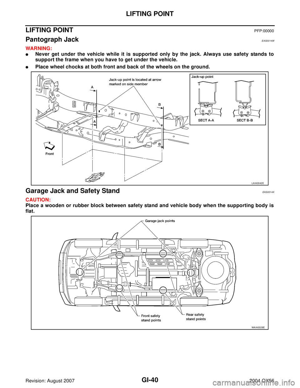
LIFTING POINTPFP:00000
Pantograph JackEAS0014W
WAR NIN G:
�Never get under the vehicle while it is supported only by the jack. Always use safety stands to
support the frame when you have to get under the vehicle.
�Place wheel chocks at both front and back of the wheels on the ground.
Garage Jack and Safety StandEAS0014X
CAUTION:
Place a wooden or rubber block between safety stand and vehicle body when the supporting body is
flat.
LAIA0042E
WAIA0028E
Page 2124 of 3371

TOW TRUCK TOWING
GI-43
C
D
E
F
G
H
I
J
K
L
MB
GI
Revision: August 20072004 QX56
4WD MODELS
NISSAN does not recommend towing automatic transmission
equipped vehicles with the drive wheels on the ground.
CAUTION:
�When towing with the front wheels on the ground or rear
wheels on the ground (If you do not use towing dollies): Set
the free-running hubs to the free position and move the
transfer case shift lever into the “2H” position.
�When towing with the front on the ground: Turn the ignition
key to the OFF position and secure the steering wheel in a
straight ahead position with a rope or similar device. Never
place the ignition key in the LOCK position. This will result
in damage to the steering lock mechanism.
Observe the following restricted towing speeds and distances.
Towing Point
CAUTION:
Never tow the vehicle using only the towing points. To avoid
damaging the vehicle body, use proper towing equipment when
towing.
Vehicle Recovery (Freeing a stuck vehicle)EAS00150
�Tow chains or cables must be attached only to the main structural members of the vehicle or the
towing hooks (if so equipped). Otherwise, the vehicle body will be damaged.
�Use the towing hook (if so equipped) only to free a vehicle stuck in sand, snow, mud, etc. Never
tow the vehicle for a long distance using only the towing hook.
�The towing hook is under tremendous force when used to free a stuck vehicle. Never pull the hook
at an angle.
�Always pull the cable straight out from the front or rear of the vehicle.
�Pulling devices should be routed so they do not touch any part of the suspension, steering, brake,
or cooling systems.
�Pulling devices such as ropes or canvas straps are not recommended for use in vehicle towing or
recovery.
WA RN ING:
�Stand clear of a stuck vehicle.
�Do not spin your tires at high speed. This could cause them to explode and result in serious injury.
Parts of your vehicle could also overheat and be damaged.Speed : Below 95 km/h (60 MPH)
Distance : Less than 800 km (500 miles)
WAIA0032E
WAIA0055E
Page 2127 of 3371
GI-46
IDENTIFICATION INFORMATION
Revision: August 20072004 QX56
IDENTIFICATION INFORMATIONPFP:00010
Model VariationEAS00153
WAIA0058E
Drive Type Body Engine Transmission Destination Grade Model
4X2 Wagon VK56DE RE5R05A (5A/T) U.S.A. LE JPKALVK-EUA
4X4 Wagon VK56DE RE5R05A (5A/T)U.S.A.
LEJPKWLVK-EUA
Canada JPKWLVK-ENA