Page 2539 of 3371

LT-108
PARKING, LICENSE PLATE AND TAIL LAMPS
Revision: August 20072004 QX56
PARKING, LICENSE PLATE AND TAIL LAMPSPFP:26550
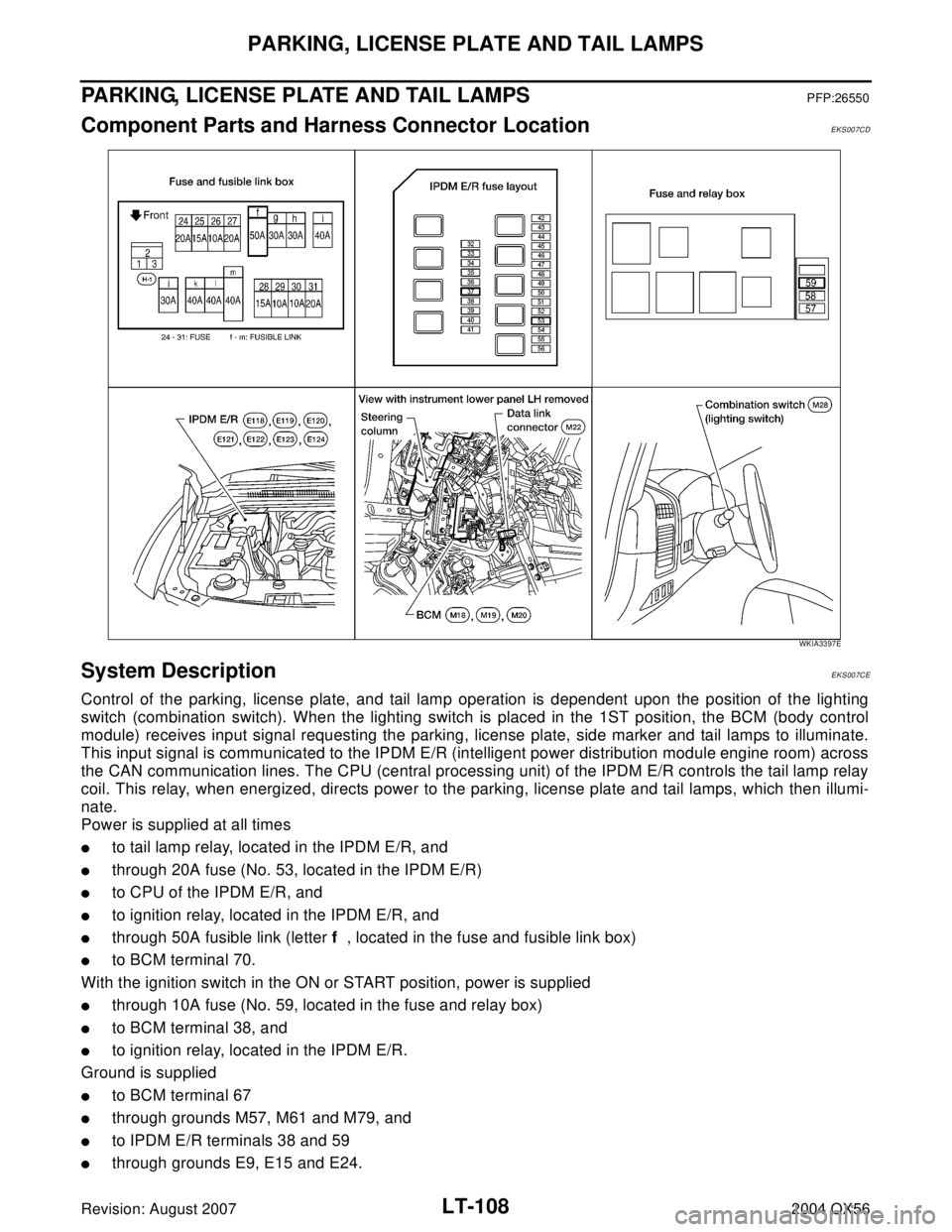
Component Parts and Harness Connector LocationEKS007CD
System DescriptionEKS007CE
Control of the parking, license plate, and tail lamp operation is dependent upon the position of the lighting
switch (combination switch). When the lighting switch is placed in the 1ST position, the BCM (body control
module) receives input signal requesting the parking, license plate, side marker and tail lamps to illuminate.
This input signal is communicated to the IPDM E/R (intelligent power distribution module engine room) across
the CAN communication lines. The CPU (central processing unit) of the IPDM E/R controls the tail lamp relay
coil. This relay, when energized, directs power to the parking, license plate and tail lamps, which then illumi-
nate.
Power is supplied at all times
�to tail lamp relay, located in the IPDM E/R, and
�through 20A fuse (No. 53, located in the IPDM E/R)
�to CPU of the IPDM E/R, and
�to ignition relay, located in the IPDM E/R, and
�through 50A fusible link (letter f , located in the fuse and fusible link box)
�to BCM terminal 70.
With the ignition switch in the ON or START position, power is supplied
�through 10A fuse (No. 59, located in the fuse and relay box)
�to BCM terminal 38, and
�to ignition relay, located in the IPDM E/R.
Ground is supplied
�to BCM terminal 67
�through grounds M57, M61 and M79, and
�to IPDM E/R terminals 38 and 59
�through grounds E9, E15 and E24.
WKIA3397E
Page 2554 of 3371
TRAILER TOW
LT-123
C
D
E
F
G
H
I
J
L
MA
B
LT
Revision: August 20072004 QX56
TRAILER TOWPFP:93020
Component Parts and Harness Connector LocationEKS007CT
System DescriptionEKS007CU
Power is supplied at all times
�through 50A fusible link (letter f , located in the fuse and fusible link box)
�to BCM (body control module) terminal 70, and
�through 10A fuse [No. 32, located in the IPDM E/R (intelligent power distribution module engine room)]
�through IPDM E/R terminal 61
�to trailer tow relay 1 terminal 3, and
�through 20A fuse (No. 53, located in the IPDM E/R)
�to CPU of the IPDM E/R, and
�through 30A fusible link (letter j , located in the fuse and fusible link box)
�to trailer tow relay 2 terminals 3 and 6, and
�through 40A fusible link (letter k , located in the fuse and fusible link box)
�to electric brake (pre-wiring) terminal 5.
With the ignition switch in the ON or START position, power is supplied
WKIA3398E
Page 2561 of 3371

LT-130
INTERIOR ROOM LAMP
Revision: August 20072004 QX56
System DescriptionEKS007CY
When room lamp and personal lamp switch is in DOOR position, room lamp and personal lamp ON/OFF is
controlled by timer according to signals from switches including key switch and key lock solenoid, front door
switch LH, unlock signal from keyfob, door lock and unlock switch, front door lock assembly LH (key cylinder
switch), ignition switch, and glass hatch ajar switch.
When room lamp and personal lamp turns ON, there is a gradual brightening over 1 second. When room lamp
and personal lamp turns OFF, there is a gradual dimming over 1 second.
The room lamp and personal lamp timer is controlled by the BCM (body control module).
Room lamp and personal lamp timer control settings can be changed with CONSULT-II.
Ignition keyhole illumination turns ON when front door LH is opened (door switch ON) or key is removed from
key cylinder. Illumination turns OFF when front door LH is closed (door switch OFF).
Step and foot lamp turns ON when front or rear doors are opened (door switch ON). Lamp turns OFF when
front and rear doors are closed (all door switches OFF).
POWER SUPPLY AND GROUND
Power is supplied at all times
�through 10A fuse [No. 19, located in the fuse block (J/B)]
�to key switch and key lock solenoid terminal 3, and
�through 15A fuse [No. 22, located in the fuse block (J/B)]
�to BCM terminal 57, and
�through 50A fusible link (letter f , located in the fuse and fusible link box)
�to BCM terminal 70.
When the key is inserted in key switch and key lock solenoid, power is supplied
�through the key switch and key lock solenoid terminal 4
�to BCM terminal 37.
With the ignition switch in the ON or START position, power is supplied
�through 10A fuse (No. 59, located in the fuse and relay box)
�to BCM terminal 38.
Ground is supplied
�to BCM terminal 67
�through grounds M57, M61 and M79.
When the front door LH is opened, ground is supplied
�to BCM terminal 47
�through case ground of front door switch LH.
When the front door RH is opened, ground is supplied
�to BCM terminal 12
�through case ground of front door switch RH.
When the rear door LH is opened, ground is supplied
�to BCM terminal 48
�through case ground of rear door switch LH.
When the rear door RH is opened, ground is supplied
�to BCM terminal 13
�through case ground of rear door switch RH.
When the liftgate is opened, ground is supplied
�to BCM terminal 43
�through back door latch (door ajar switch) terminal 7
�through back door latch (door ajar switch) terminal 8
�through grounds B7 and B19.
When the glass hatch is opened, ground is supplied
�to BCM terminal 42
�through case ground of glass hatch ajar switch.
Page 2583 of 3371

LT-152
ILLUMINATION
Revision: August 20072004 QX56
ILLUMINATIONPFP:27545
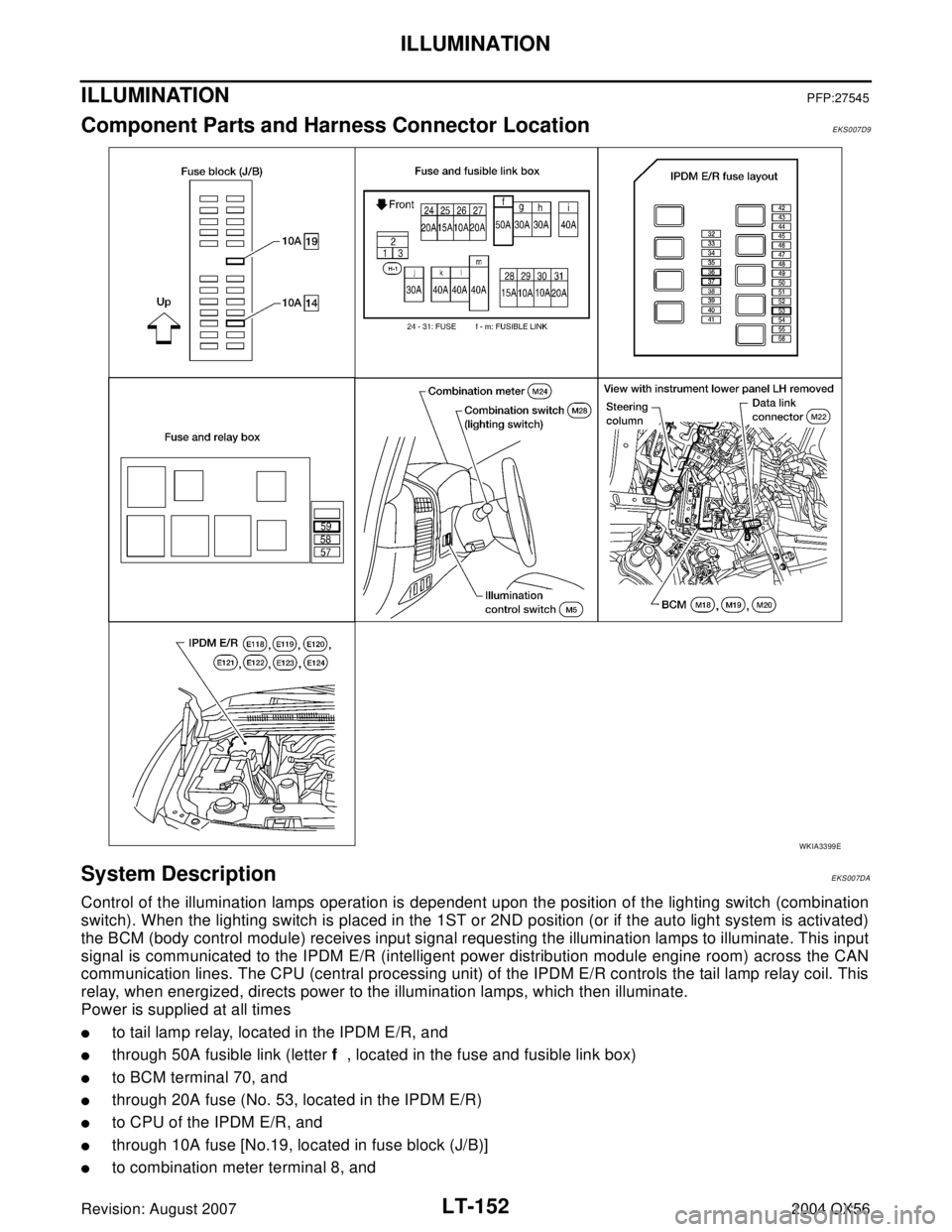
Component Parts and Harness Connector LocationEKS007D9
System DescriptionEKS007DA
Control of the illumination lamps operation is dependent upon the position of the lighting switch (combination
switch). When the lighting switch is placed in the 1ST or 2ND position (or if the auto light system is activated)
the BCM (body control module) receives input signal requesting the illumination lamps to illuminate. This input
signal is communicated to the IPDM E/R (intelligent power distribution module engine room) across the CAN
communication lines. The CPU (central processing unit) of the IPDM E/R controls the tail lamp relay coil. This
relay, when energized, directs power to the illumination lamps, which then illuminate.
Power is supplied at all times
�to tail lamp relay, located in the IPDM E/R, and
�through 50A fusible link (letter f , located in the fuse and fusible link box)
�to BCM terminal 70, and
�through 20A fuse (No. 53, located in the IPDM E/R)
�to CPU of the IPDM E/R, and
�through 10A fuse [No.19, located in fuse block (J/B)]
�to combination meter terminal 8, and
WKIA3399E
Page 2614 of 3371
OIL PUMP
LU-13
C
D
E
F
G
H
I
J
K
L
MA
LU
Revision: August 20072004 QX56
OIL PUMPPFP:15010
Removal and InstallationEBS00I4N
REMOVAL
1. Remove front cover. Refer to EM-35, "TIMING CHAIN" .
2. Remove the oil pump drive spacer.
3. Remove the oil pump.
INSTALLATION
1. Installation is in the reverse order of removal, paying attention of the following:
�When inserting the oil pump drive spacer, align the crankshaft
key and the flat face of the inner rotor.
�If they are not aligned, rotate the oil pump inner rotor by hand.
�Make sure that each part is aligned and tap lightly until it
reached the end.
WBIA0415E
1. Oil pump body 2. Outer rotor 3. Inner rotor
4. Oil pump cover 5. Oil pump drive spacer 6. Regulator valve
7. Regulator spring 8. Regulator plug
KBIA2512E
KBIA2490E
Page 2615 of 3371

LU-14Revision: August 2007
OIL PUMP
2004 QX56
INSPECTION AFTER INSTALLATION
�Start the engine, and check for leaks of engine oil.
�Stop engine and wait 10 minutes.
�Check level and add engine oil as required. Refer to LU-7, "ENGINE OIL" .
Disassembly and AssemblyEBS00I4O
DISASSEMBLY
1. Remove oil pump cover.
2. Remove inner rotor and outer rotor from oil pump body.
3. Remove regulator plug, regulator spring and regulator valve.
INSPECTION AFTER DISASSEMBLY
Clearance of Oil Pump Parts
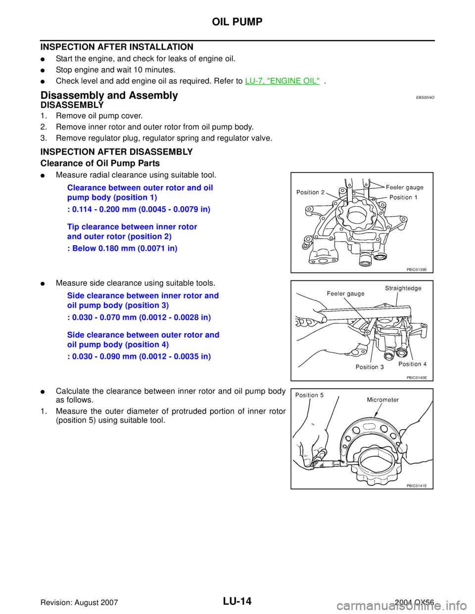
�Measure radial clearance using suitable tool.
�Measure side clearance using suitable tools.
�Calculate the clearance between inner rotor and oil pump body
as follows.
1. Measure the outer diameter of protruded portion of inner rotor
(position 5) using suitable tool.Clearance between outer rotor and oil
pump body (position 1)
: 0.114 - 0.200 mm (0.0045 - 0.0079 in)
Tip clearance between inner rotor
and outer rotor (position 2)
: Below 0.180 mm (0.0071 in)
PBIC0139E
Side clearance between inner rotor and
oil pump body (position 3)
: 0.030 - 0.070 mm (0.0012 - 0.0028 in)
Side clearance between outer rotor and
oil pump body (position 4)
: 0.030 - 0.090 mm (0.0012 - 0.0035 in)
PBIC0140E
PBIC0141E
Page 2616 of 3371
OIL PUMP
LU-15
C
D
E
F
G
H
I
J
K
L
MA
LU
Revision: August 20072004 QX56
2. Measure the inner diameter of oil pump body to brazed portion
(position 6) using suitable tool.
3. Calculate the clearance using the following formula.
�(Clearance) = (Inner diameter of oil pump body) - (Outer diameter of inner rotor)
Regulator Valve Clearance
Check regulator valve to oil pump cover clearance as follows:
�(Clearance) = D1 (Valve hole diameter) - D2 (Outer Diameter
of valve)
CAUTION:
�Coat regulator valve with engine oil.
�Check that it falls smoothly into the regulator valve hole
by its own weight.
ASSEMBLY
Installation is in the reverse order of removal.
NOTE:
Install the inner rotor and outer rotor with the punched marks on the
oil pump cover side.
PBIC0142E
Inner rotor to brazed portion of housing
clearance
: 0.045 - 0.091 mm (0.0018 - 0.0036 in)
Regulator valve to oil pump cover
: 0.040 - 0.097 mm (0.0016 - 0.0038 in)
PBIC0143E
PBIC0144E
Page 2617 of 3371
LU-16Revision: August 2007
SERVICE DATA AND SPECIFICATIONS (SDS)
2004 QX56
SERVICE DATA AND SPECIFICATIONS (SDS)PFP:00030
Standard and LimitEBS00I4P
OIL PRESSURE
Unit: kPa (kg/cm2 , psi)
OIL PUMP
Unit: mm (in)
REGULATOR VALVE
Unit: mm (in)
ENGINE OIL CAPACITY (APPROXIMATE)
Unit: (US qt, Imp qt) Engine speed Approximate discharge oil pressure
Idle speed More than 98 (1.0, 14)
2,000 rpm More than 294 (3.0, 43)
Body to outer rotor radial clearance 0.114 - 0.200 (0.0045 - 0.0079)
Inner rotor to outer rotor tip clearance Below 0.180 (0.0071)
Body to inner rotor side clearance 0.030 - 0.070 (0.0012 - 0.0028)
Body to outer rotor side clearance 0.030 - 0.090 (0.0012 - 0.0035)
Inner rotor to brazed portion of housing clearance 0.045 - 0.091 (0.0018 - 0.0036)
Regulator valve to oil pump cover clearance 0.040 - 0.097 (0.0016 - 0.0038)
Drain and refillWith oil filter change 6.2 (6 1/2, 5 1/2)
Without oil filter change 5.9 (6 1/4, 5 1/4)
Dry engine (engine overhaul) 7.6 (8, 6 3/4)