Page 1419 of 3371
EC-228Revision: August 2007
DTC P0181 FTT SENSOR
2004 QX56
Diagnostic ProcedureUBS00H38
1. CHECK DTC WITH COMBINATION METER
Refer to DI-5, "
COMBINATION METERS" .
OK or NG
OK >> GO TO 2.
NG >> Go to DI-22, "
Fuel Level Sensor Unit Inspection" .
2. CHECK GROUND CONNECTIONS
1. Turn ignition switch OFF.
2. Loosen and retighten three ground screws on the body.
Refer to EC-133, "
Ground Inspection" .
OK or NG
OK >> GO TO 3.
NG >> Repair or replace ground connections.
3. CHECK FUEL TANK TEMPERATURE SENSOR POWER SUPPLY CIRCUIT
1. Disconnect “fuel level sensor unit and fuel pump” harness con-
nector.
2. Turn ignition switch ON.
3. Check voltage between “fuel level sensor unit and fuel pump”
terminal 4 and ground with CONSULT-II or tester.
OK or NG
OK >> GO TO 5.
NG >> GO TO 4.
BBIA0354E
BBIA0583E
Voltage: Approximately 5V
PBIB0932E
Page 1424 of 3371
DTC P0182, P0183 FTT SENSOR
EC-233
C
D
E
F
G
H
I
J
K
L
MA
EC
Revision: August 20072004 QX56
Diagnostic ProcedureUBS00H3F
1. CHECK DTC WITH COMBINATION METER
Refer to DI-5, "
COMBINATION METERS" .
OK or NG
OK >> GO TO 2.
NG >> Go to DI-22, "
Fuel Level Sensor Unit Inspection" .
2. CHECK GROUND CONNECTIONS
1. Turn ignition switch OFF.
2. Loosen and retighten three ground screws on the body.
Refer to EC-133, "
Ground Inspection" .
OK or NG
OK >> GO TO 3.
NG >> Repair or replace ground connections.
3. CHECK FUEL TANK TEMPERATURE SENSOR POWER SUPPLY CIRCUIT
1. Disconnect “fuel level sensor unit and fuel pump” harness con-
nector.
2. Turn ignition switch ON.
3. Check voltage between “fuel level sensor unit and fuel pump”
terminal 4 and ground with CONSULT-II or tester.
OK or NG
OK >> GO TO 5.
NG >> GO TO 4.
BBIA0354E
BBIA0583E
Voltage: Approximately 5V
PBIB0932E
Page 1430 of 3371
DTC P0222, P0223 TP SENSOR
EC-239
C
D
E
F
G
H
I
J
K
L
MA
EC
Revision: August 20072004 QX56
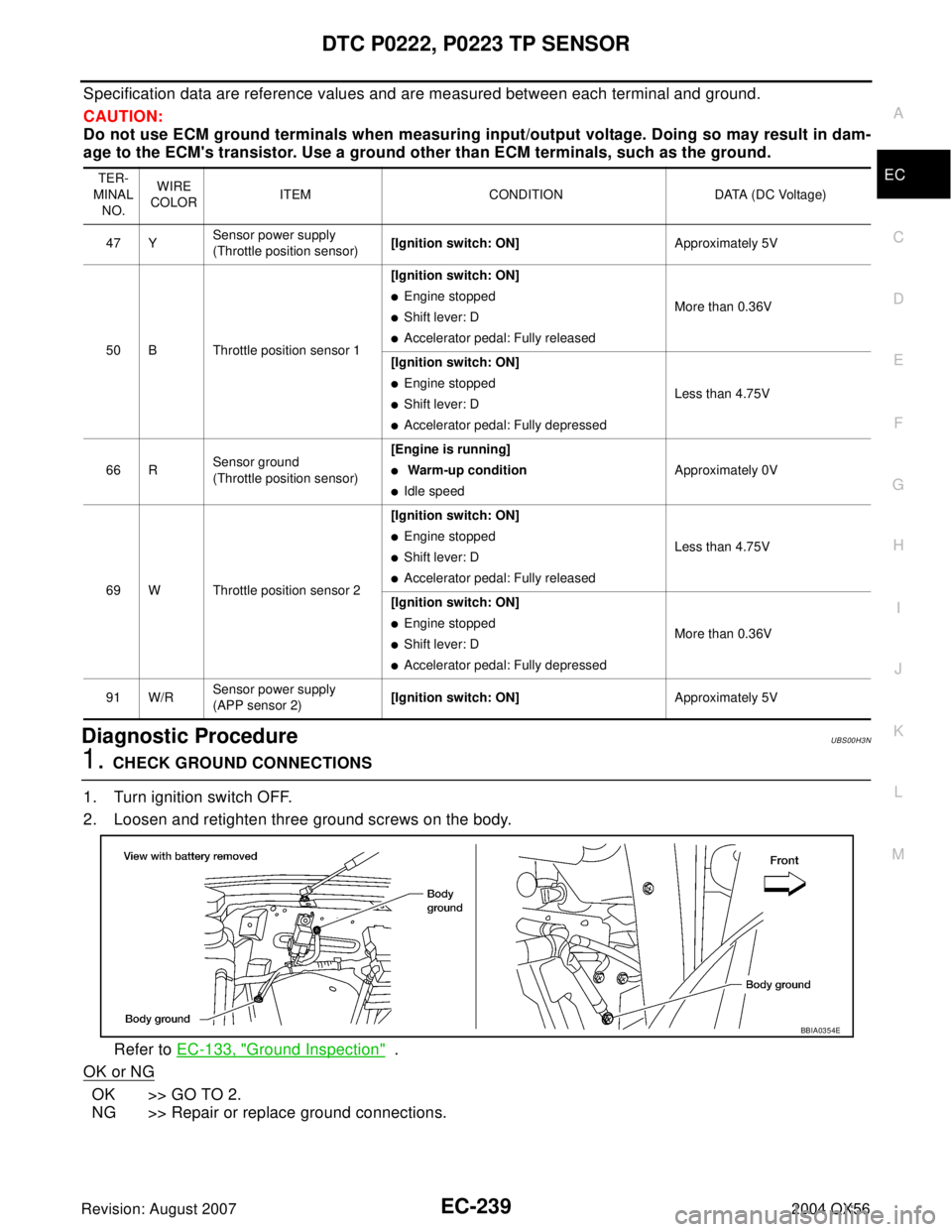
Specification data are reference values and are measured between each terminal and ground.
CAUTION:
Do not use ECM ground terminals when measuring input/output voltage. Doing so may result in dam-
age to the ECM's transistor. Use a ground other than ECM terminals, such as the ground.
Diagnostic ProcedureUBS00H3N
1. CHECK GROUND CONNECTIONS
1. Turn ignition switch OFF.
2. Loosen and retighten three ground screws on the body.
Refer to EC-133, "
Ground Inspection" .
OK or NG
OK >> GO TO 2.
NG >> Repair or replace ground connections.
TER-
MINAL
NO.WIRE
COLOR ITEM CONDITION DATA (DC Voltage)
47 YSensor power supply
(Throttle position sensor)[Ignition switch: ON]Approximately 5V
50 B Throttle position sensor 1[Ignition switch: ON]
�Engine stopped
�Shift lever: D
�Accelerator pedal: Fully releasedMore than 0.36V
[Ignition switch: ON]
�Engine stopped
�Shift lever: D
�Accelerator pedal: Fully depressedLess than 4.75V
66 RSensor ground
(Throttle position sensor)[Engine is running]
� Warm-up condition
�Idle speedApproximately 0V
69 W Throttle position sensor 2[Ignition switch: ON]
�Engine stopped
�Shift lever: D
�Accelerator pedal: Fully releasedLess than 4.75V
[Ignition switch: ON]
�Engine stopped
�Shift lever: D
�Accelerator pedal: Fully depressedMore than 0.36V
91 W/RSensor power supply
(APP sensor 2)[Ignition switch: ON]Approximately 5V
BBIA0354E
Page 1443 of 3371
EC-252Revision: August 2007
DTC P0327, P0328, P0332, P0333 KS
2004 QX56
Specification data are reference values and are measured between each terminal and ground.
CAUTION:
Do not use ECM ground terminals when measuring input/output voltage. Doing so may result in dam-
age to the ECM's transistor. Use a ground other than ECM terminals, such as the ground.
Diagnostic ProcedureUBS00H3X
1. CHECK KNOCK SENSOR INPUT SIGNAL CIRCUIT FOR OPEN AND SHORT-I
1. Turn ignition switch OFF.
2. Disconnect ECM harness connector.
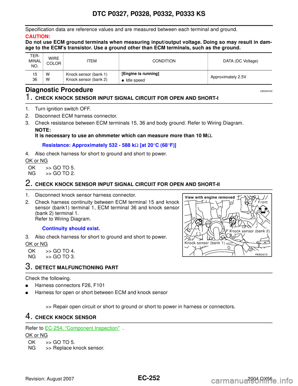
3. Check resistance between ECM terminals 15, 36 and body ground. Refer to Wiring Diagram.
NOTE:
It is necessary to use an ohmmeter which can measure more than 10 MΩ.
4. Also check harness for short to ground and short to power.
OK or NG
OK >> GO TO 5.
NG >> GO TO 2.
2. CHECK KNOCK SENSOR INPUT SIGNAL CIRCUIT FOR OPEN AND SHORT-II
1. Disconnect knock sensor harness connector.
2. Check harness continuity between ECM terminal 15 and knock
sensor (bank1) terminal 1, ECM terminal 36 and knock sensor
(bank 2) terminal 1.
Refer to Wiring Diagram.
3. Also check harness for short to ground and short to power.
OK or NG
OK >> GO TO 4.
NG >> GO TO 3.
3. DETECT MALFUNCTIONING PART
Check the following.
�Harness connectors F26, F101
�Harness for open or short between ECM and knock sensor
>> Repair open circuit or short to ground or short to power in harness or connectors.
4. CHECK KNOCK SENSOR
Refer to EC-254, "
Component Inspection" .
OK or NG
OK >> GO TO 5.
NG >> Replace knock sensor.
TER-
MINAL
NO.WIRE
COLORITEM CONDITION DATA (DC Voltage)
15
36W
WKnock sensor (bank 1)
Knock sensor (bank 2)[Engine is running]
�Idle speedApproximately 2.5V
Resistance: Approximately 532 - 588 kΩ [at 20°C (68°F)]
Continuity should exist.
PBIB0021E
Page 1444 of 3371
DTC P0327, P0328, P0332, P0333 KS
EC-253
C
D
E
F
G
H
I
J
K
L
MA
EC
Revision: August 20072004 QX56
5. CHECK GROUND CONNECTIONS
1. Turn ignition switch OFF.
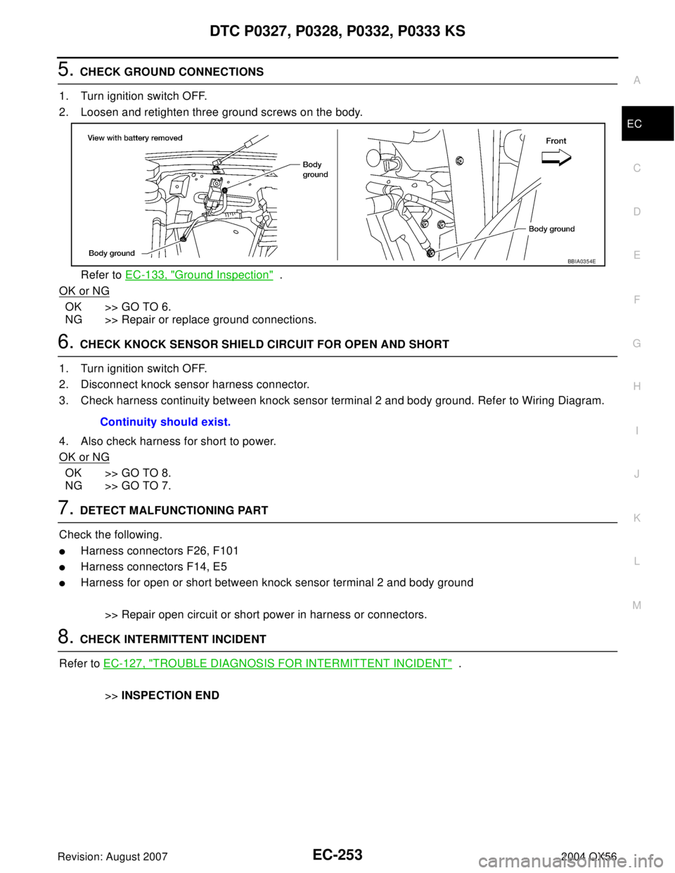
2. Loosen and retighten three ground screws on the body.
Refer to EC-133, "
Ground Inspection" .
OK or NG
OK >> GO TO 6.
NG >> Repair or replace ground connections.
6. CHECK KNOCK SENSOR SHIELD CIRCUIT FOR OPEN AND SHORT
1. Turn ignition switch OFF.
2. Disconnect knock sensor harness connector.
3. Check harness continuity between knock sensor terminal 2 and body ground. Refer to Wiring Diagram.
4. Also check harness for short to power.
OK or NG
OK >> GO TO 8.
NG >> GO TO 7.
7. DETECT MALFUNCTIONING PART
Check the following.
�Harness connectors F26, F101
�Harness connectors F14, E5
�Harness for open or short between knock sensor terminal 2 and body ground
>> Repair open circuit or short power in harness or connectors.
8. CHECK INTERMITTENT INCIDENT
Refer to EC-127, "
TROUBLE DIAGNOSIS FOR INTERMITTENT INCIDENT" .
>>INSPECTION END
BBIA0354E
Continuity should exist.
Page 1448 of 3371
DTC P0335 CKP SENSOR (POS)
EC-257
C
D
E
F
G
H
I
J
K
L
MA
EC
Revision: August 20072004 QX56
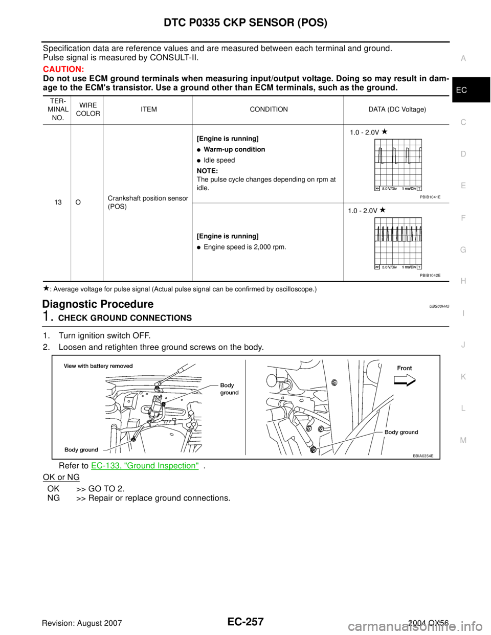
Specification data are reference values and are measured between each terminal and ground.
Pulse signal is measured by CONSULT-II.
CAUTION:
Do not use ECM ground terminals when measuring input/output voltage. Doing so may result in dam-
age to the ECM's transistor. Use a ground other than ECM terminals, such as the ground.
: Average voltage for pulse signal (Actual pulse signal can be confirmed by oscilloscope.)
Diagnostic ProcedureUBS00H45
1. CHECK GROUND CONNECTIONS
1. Turn ignition switch OFF.
2. Loosen and retighten three ground screws on the body.
Refer to EC-133, "
Ground Inspection" .
OK or NG
OK >> GO TO 2.
NG >> Repair or replace ground connections.
TER-
MINAL
NO.WIRE
COLORITEM CONDITION DATA (DC Voltage)
13 OCrankshaft position sensor
(POS)[Engine is running]
�Warm-up condition
�Idle speed
NOTE:
The pulse cycle changes depending on rpm at
idle. 1.0 - 2.0V
[Engine is running]
�Engine speed is 2,000 rpm.1.0 - 2.0V
PBIB1041E
PBIB1042E
BBIA0354E
Page 1449 of 3371
EC-258Revision: August 2007
DTC P0335 CKP SENSOR (POS)
2004 QX56
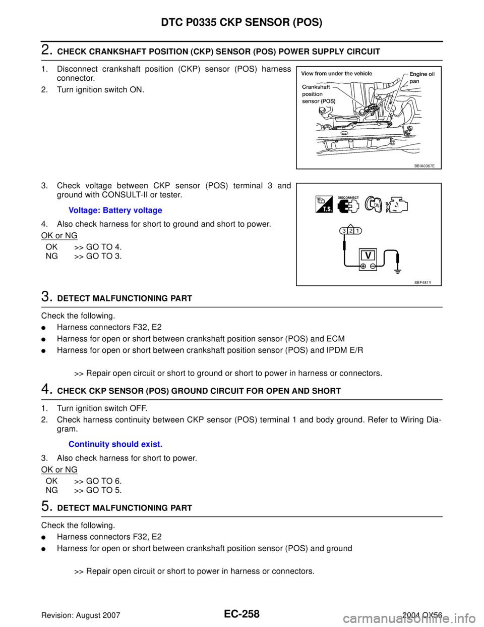
2. CHECK CRANKSHAFT POSITION (CKP) SENSOR (POS) POWER SUPPLY CIRCUIT
1. Disconnect crankshaft position (CKP) sensor (POS) harness
connector.
2. Turn ignition switch ON.
3. Check voltage between CKP sensor (POS) terminal 3 and
ground with CONSULT-II or tester.
4. Also check harness for short to ground and short to power.
OK or NG
OK >> GO TO 4.
NG >> GO TO 3.
3. DETECT MALFUNCTIONING PART
Check the following.
�Harness connectors F32, E2
�Harness for open or short between crankshaft position sensor (POS) and ECM
�Harness for open or short between crankshaft position sensor (POS) and IPDM E/R
>> Repair open circuit or short to ground or short to power in harness or connectors.
4. CHECK CKP SENSOR (POS) GROUND CIRCUIT FOR OPEN AND SHORT
1. Turn ignition switch OFF.
2. Check harness continuity between CKP sensor (POS) terminal 1 and body ground. Refer to Wiring Dia-
gram.
3. Also check harness for short to power.
OK or NG
OK >> GO TO 6.
NG >> GO TO 5.
5. DETECT MALFUNCTIONING PART
Check the following.
�Harness connectors F32, E2
�Harness for open or short between crankshaft position sensor (POS) and ground
>> Repair open circuit or short to power in harness or connectors.
BBIA0367E
Voltage: Battery voltage
SEF 4 81 Y
Continuity should exist.
Page 1454 of 3371
DTC P0340 CAMSHAFT POSITION (CMP) SENSOR (PHASE)
EC-263
C
D
E
F
G
H
I
J
K
L
MA
EC
Revision: August 20072004 QX56
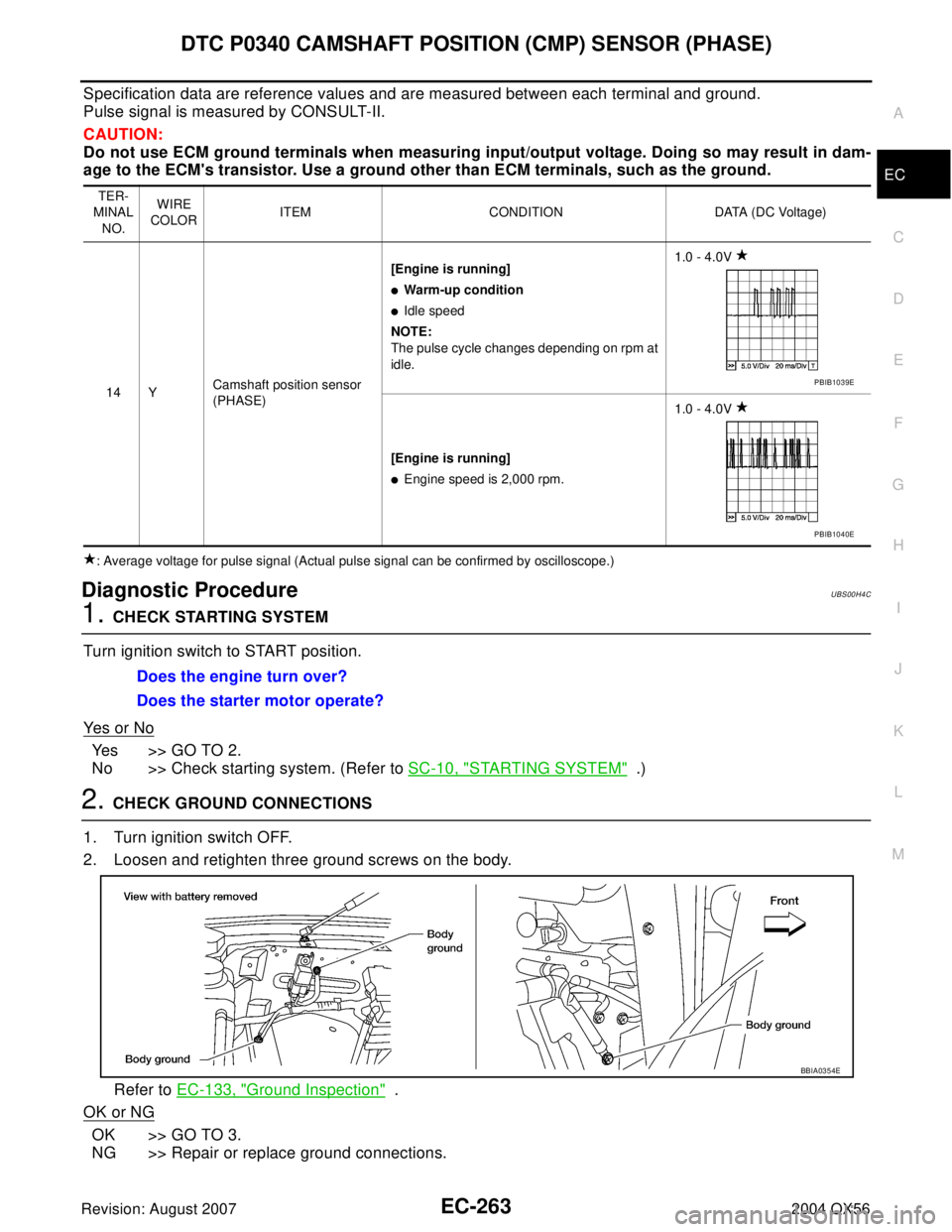
Specification data are reference values and are measured between each terminal and ground.
Pulse signal is measured by CONSULT-II.
CAUTION:
Do not use ECM ground terminals when measuring input/output voltage. Doing so may result in dam-
age to the ECM's transistor. Use a ground other than ECM terminals, such as the ground.
: Average voltage for pulse signal (Actual pulse signal can be confirmed by oscilloscope.)
Diagnostic ProcedureUBS00H4C
1. CHECK STARTING SYSTEM
Turn ignition switch to START position.
Ye s o r N o
Yes >> GO TO 2.
No >> Check starting system. (Refer to SC-10, "
STARTING SYSTEM" .)
2. CHECK GROUND CONNECTIONS
1. Turn ignition switch OFF.
2. Loosen and retighten three ground screws on the body.
Refer to EC-133, "
Ground Inspection" .
OK or NG
OK >> GO TO 3.
NG >> Repair or replace ground connections.
TER-
MINAL
NO.WIRE
COLORITEM CONDITION DATA (DC Voltage)
14 YCamshaft position sensor
(PHASE)[Engine is running]
�Warm-up condition
�Idle speed
NOTE:
The pulse cycle changes depending on rpm at
idle.1.0 - 4.0V
[Engine is running]
�Engine speed is 2,000 rpm.1.0 - 4.0V
PBIB1039E
PBIB1040E
Does the engine turn over?
Does the starter motor operate?
BBIA0354E