Page 118 of 3371

TROUBLE DIAGNOSIS
AT-47
D
E
F
G
H
I
J
K
L
MA
B
AT
Revision: August 20072004 QX56
DIAGNOSTIC WORKSHEET
Information From Customer
KEY POINTS
�WHAT..... Vehicle & A/T model
�WHEN..... Date, Frequencies
�WHERE..... Road conditions
�HOW..... Operating conditions, Symptoms
Diagnostic Worksheet Chart
Customer name MR/MS Model & Year VIN
Trans. Model Engine Mileage
Malfunction Date Manuf. Date In Service Date
Frequency❏ Continuous❏ Intermittent ( times a day)
Symptoms❏ Vehicle does not move. (❏ Any position❏ Particular position)
❏ No up-shift (❏ 1st → 2nd❏ 2nd → 3rd❏ 3rd → 4th ❏ 4th → 5th)
❏ No down-shift (❏ 5th → 4th ❏ 4th → 3rd❏ 3rd → 2nd❏ 2nd → 1st)
❏ Lock-up malfunction
❏ Shift point too high or too low.
❏ Shift shock or slip (❏ N → D❏ Lock-up❏ Any drive position)
❏ Noise or vibration
❏ No kick down
❏ No pattern select
❏ Others
()
AT CHECK indicator lamp Blinks for about 8 seconds.
❏ Continuously lit❏ Not lit
Malfunction indicator lamp (MIL)❏ Continuously lit❏ Not lit
1❏ Read the item on “cautions concerning fail-safe and understand the customer's complaint.AT- 4 3
2❏ ATF inspection
AT- 5 8❏ Leak (Repair leak location.)
❏ Sta te
❏ Amount
3❏ Stall test and line pressure test
AT- 5 8
, AT-
59
❏ Stall test
❏ Torque converter one-way clutch
❏ Front brake
❏ High and low reverse clutch
❏ Low coast brake
❏ Forward brake
❏ Reverse brake
❏ Forward one-way clutch❏ 1st one-way clutch
❏ 3rd one-way clutch
❏ Engine
❏ Line pressure low
❏ Except for input clutch and direct
clutch, clutches and brakes OK
❏ Line pressure inspection - Suspected part:
Page 307 of 3371
AT-236
A/T SHIFT LOCK SYSTEM
Revision: August 20072004 QX56
A/T SHIFT LOCK SYSTEMPFP:34950
DescriptionUCS002J 6
�The electrical key interlock mechanism also operates as a shift lock:
With the ignition switch turned to ON, the selector lever cannot be shifted from “P” (parking) to any other
position unless the brake pedal is depressed.
With the key removed, the selector lever cannot be shifted from “P” to any other position.
The key cannot be removed unless the selector lever is placed in “P”.
�The shift lock and key interlock mechanisms are controlled by the ON-OFF operation of the shift lock sole-
noid and by the operation of the rotator and slider located inside the key cylinder, respectively.
Shift Lock System Electrical Parts LocationUCS002J 7
LCIA0326E
Page 309 of 3371

AT-238
A/T SHIFT LOCK SYSTEM
Revision: August 20072004 QX56
Shift Lock Control Unit Reference ValuesUCS002J 9
SHIFT LOCK HARNESS CONNECTOR TERMINALS LAYOUT
SHIFT LOCK CONTROL UNIT INSPECTION TABLE
Data are reference values.
NOTE:
Confirm that the pointer swings only momentarily because the output time is so short. If the inspection is done with an oscilloscope, it
should be observed that the power source voltage lasts for 3.5 to 10 ms.
LCIA0327E
TER-
MINAL
NO.WIRE
COLORITEM CONDITIONVOLTAGE
(V)
1 Y/R Power sourceIgnition switch: “ON” Battery voltage
Ignition switch: “OFF” Battery voltage
2L/R Detention switch
(for key)When selector lever is not in "P" position with key inserted. Battery voltage
Except the above Approx. 0V
3GRDetention switch
(for shift)When selector lever is not in "P" position Battery voltage
Except the above Approx. 0V
4 R/G Stop lamp switchWhen brake pedal is depressed Battery voltage
When brake pedal is released Approx. 0V
5W/RVehicle speed sig-
nal——
——
6 G/R Ignition signalIgnition switch: “OFF” Approx. 0V
Ignition switch: “ON” Battery voltage
7 R/W Shift lock solenoidWhen brake pedal is depressed with ignition switch "ON". Approx. 0V
When brake pedal is depressed. Battery voltage
8 B Ground — Approx. 0V
9 G/W Key lock solenoidWhen the selector lever is set to a position other than the “P”
position, and the key switch is turned from “ON” to “OFF”Battery voltage for
approx. 0.1 sec.
(Note)
Except the above Approx. 0V
10 W/G Key unlock solenoidWhen ignition switch is not in "ON” position with key inserted.Battery voltage for
approx. 0.1 sec.
(Note)
Except the above Approx. 0V
Page 310 of 3371

A/T SHIFT LOCK SYSTEM
AT-239
D
E
F
G
H
I
J
K
L
MA
B
AT
Revision: August 20072004 QX56
Component InspectionUCS002J A
SHIFT LOCK SOLENOID
�Check operation by applying battery voltage to the A/T device.
CAUTION:
Be sure to apply the voltage of the correct polarity to the
respective terminals. Otherwise, the part may be damaged.
DETENTION SWITCH
For key:
�Check continuity between terminals of the A/T device.
DETENTION SWITCH
For shift:
�Check continuity between terminals of the A/T device.
KEY LOCK SOLENOID
Key lock
�Check operation by applying battery voltage to key switch and
key lock solenoid.
CAUTION:
Be careful not to cause burnout of the harness.
Connector No. Terminal No.
M203 9 (Battery voltage) - 10 (Ground)
LCIA0328E
ConditionConnector
No.Terminal No. Continuity
When selector lever is “P”
position.
M203 5 - 6No
When selector lever is not “P”
position.Ye s
LIIA1599E
ConditionConnector
No.Terminal No. Continuity
When selector lever is “P”
position.
M203 3 - 4No
When selector lever is not “P”
position.Ye s
WCIA0401E
Connector No. Terminal No. (Wire color)
M27 1 (Battery voltage) - 2 (Ground)
WCIA0240E
Page 311 of 3371
AT-240
A/T SHIFT LOCK SYSTEM
Revision: August 20072004 QX56
Key unlock
�Check operation by applying battery voltage to key switch and
key lock solenoid.
CAUTION:
Be careful not to cause burnout of the harness.
KEY SWITCH
�Check continuity between terminals of the key switch and key
lock solenoid.
STOP LAMP SWITCH
�Check continuity between terminals of the stop lamp switch.
Check stop lamp switch after adjusting brake pedal.
Connector No. Terminal No. (Wire color)
M27 2 (Battery voltage) - 1 (Ground)
WCIA0241E
Condition Connector No.Te r m i n a l N o .
(Wire color)Continuity
Key inserted
M27 3 - 4Ye s
Key withdrawn No
WCIA0242E
ConditionConnector
No.Te r m i n a l N o .
(Wire color)Continuity
When brake pedal is depressed
E38 3 - 4Ye s
When brake pedal is released No
SCIA2126E
Page 655 of 3371

AV-68
NAVIGATION SYSTEM
Revision: August 20072004 QX56
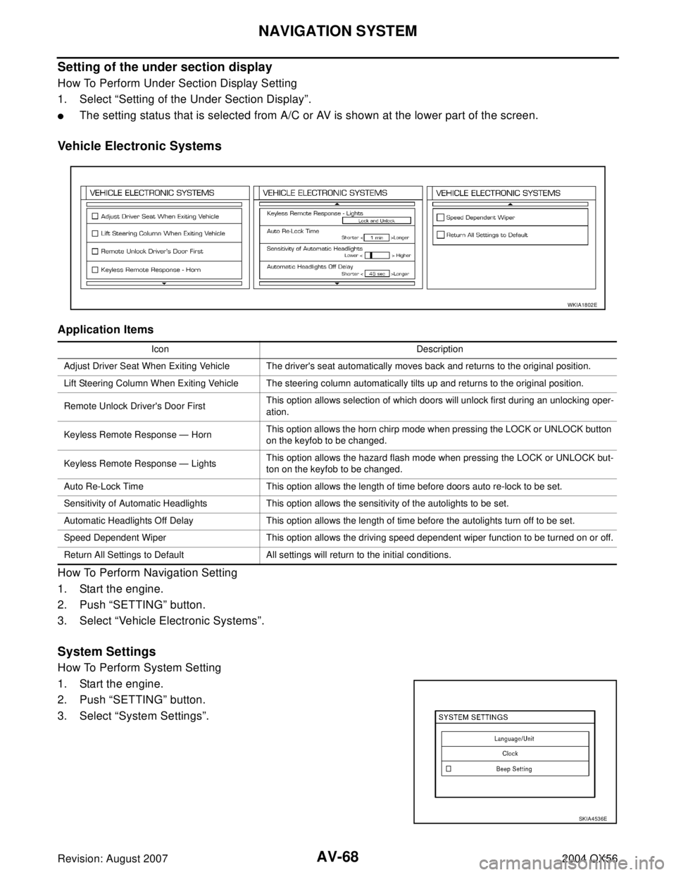
Setting of the under section display
How To Perform Under Section Display Setting
1. Select “Setting of the Under Section Display”.
�The setting status that is selected from A/C or AV is shown at the lower part of the screen.
Vehicle Electronic Systems
Application Items
How To Perform Navigation Setting
1. Start the engine.
2. Push “SETTING” button.
3. Select “Vehicle Electronic Systems”.
System Settings
How To Perform System Setting
1. Start the engine.
2. Push “SETTING” button.
3. Select “System Settings”.
Icon Description
Adjust Driver Seat When Exiting Vehicle The driver's seat automatically moves back and returns to the original position.
Lift Steering Column When Exiting Vehicle The steering column automatically tilts up and returns to the original position.
Remote Unlock Driver's Door FirstThis option allows selection of which doors will unlock first during an unlocking oper-
ation.
Keyless Remote Response — HornThis option allows the horn chirp mode when pressing the LOCK or UNLOCK button
on the keyfob to be changed.
Keyless Remote Response — LightsThis option allows the hazard flash mode when pressing the LOCK or UNLOCK but-
ton on the keyfob to be changed.
Auto Re-Lock Time This option allows the length of time before doors auto re-lock to be set.
Sensitivity of Automatic Headlights This option allows the sensitivity of the autolights to be set.
Automatic Headlights Off Delay This option allows the length of time before the autolights turn off to be set.
Speed Dependent Wiper This option allows the driving speed dependent wiper function to be turned on or off.
Return All Settings to Default All settings will return to the initial conditions.
WKIA1802E
SKIA4536E
Page 656 of 3371

NAVIGATION SYSTEM
AV-69
C
D
E
F
G
H
I
J
L
MA
B
AV
Revision: August 20072004 QX56
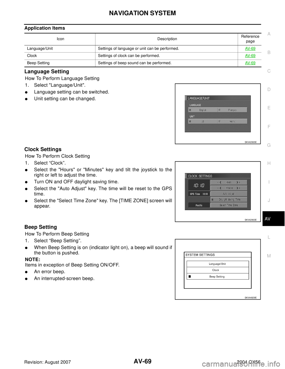
Application Items
Language Setting
How To Perform Language Setting
1. Select "Language/Unit".
�Language setting can be switched.
�Unit setting can be changed.
Clock Settings
How To Perform Clock Setting
1. Select “Clock”.
�Select the "Hours" or "Minutes" key and tilt the joystick to the
right or left to adjust the time.
�Turn ON and OFF daylight saving time.
�Select the "Auto Adjust" key. The time will be reset to the GPS
time.
�Select the "Select Time Zone" key. The [TIME ZONE] screen will
appear.
Beep Setting
How To Perform Beep Setting
1. Select “Beep Setting”.
�When Beep Setting is on (indicator light on), a beep will sound if
the button is pushed.
NOTE:
Items in exception of Beep Setting ON/OFF.
�An error beep.
�An interrupted-screen beep.
Icon DescriptionReference
page
Language/Unit Settings of language or unit can be performed.AV- 6 9
Clock Settings of clock can be performed.AV- 6 9
Beep Setting Settings of beep sound can be performed.AV- 6 9
SKIA2065E
SKIA2063E
SKIA4829E
Page 658 of 3371
NAVIGATION SYSTEM
AV-71
C
D
E
F
G
H
I
J
L
MA
B
AV
Revision: August 20072004 QX56
“HEADING” MODE
�To display North up, select “North up”.
�To display the car heading up, select “Heading up”.
“NEARBY DISPLAY ICONS” MODE
�Select an icon to display on the map screen.
“SAVE CURRENT LOCATION” MODE
�The current vehicle location can be registered in “Address
Book”.
NOTE:
“Address Book” can store 50 items maximum.
“ADJUST CURRENT LOCATION” MODE
1. Move marker to correct location.
2. Select "SET" and then vehicle mark will be located in the current
position.
3. Select an icon “right” or “left” to calibrate the heading direction.
(Arrow marks will rotate corresponding to the calibration key.)
SKIA0561E
SKIA0562E
SKIA0556E
SKIA0563E