Page 1287 of 3371

EC-96Revision: August 2007
TROUBLE DIAGNOSIS
2004 QX56
ECM Harness Connector Terminal LayoutUBS00H03
ECM Terminals and Reference ValueUBS00H04
PREPARATION
1. ECM is located in the engine room passenger side behind bat-
tery.
2. Remove ECM harness connector.
3. When disconnecting ECM harness connector, loosen it with
levers as far as they will go as shown in the figure.
4. Connect a break-out box (SST) and Y-cable adapter (SST)
between the ECM and ECM harness connector.
�Use extreme care not to touch 2 pins at one time.
�Data is for comparison and may not be exact.
ECM INSPECTION TABLE
Specification data are reference values and are measured between each terminal and ground.
Pulse signal is measured by CONSULT-II.
CAUTION:
Do not use ECM ground terminals when measuring input/output voltage. Doing so may result in dam-
age to the ECMs transistor. Use a ground other than ECM terminals, such as the ground.
PBIB1192E
BBIA0386E
BBIA0387E
TER-
MINAL
NO.WIRE
COLORITEM CONDITION DATA (DC Voltage)
1 B ECM ground[Engine is running]
�Idle speedBody ground
2O/BA/F sensor 1 heater
(bank 1)[Engine is running]
�Warm-up condition
�Idle speedApproximately 5V
PBIB1584E
Page 1294 of 3371

CONSULT-II FunctionUBS00H05")
TROUBLE DIAGNOSIS
EC-103
C
D
E
F
G
H
I
J
K
L
MA
EC
Revision: August 20072004 QX56
: Average voltage for pulse signal (Actual pulse signal can be confirmed by oscilloscope.)
CONSULT-II FunctionUBS00H05
FUNCTION
*1: The following emission-related diagnostic information is cleared when the ECM memory is erased.
�Diagnostic trouble codes
�1st trip diagnostic trouble codes
�Freeze frame data
�1st trip freeze frame data 109 B/R Ignition switch[Ignition switch: OFF]0V
[Ignition switch: ON]BATTERY VOLTAGE
(11 - 14V)
111 W /BECM relay
(Self shut-off)[Engine is running]
[Ignition switch: OFF]
�For a few seconds after turning ignition
switch OFF0 - 1.5V
[Ignition switch: OFF]
�More than a few seconds after turning igni-
tion switch OFFBATTERY VOLTAGE
(11 - 14V)
113 GR Fuel pump relay[Ignition switch: ON]
�For 1 second after turning ignition switch
ON
[Engine is running]0 - 1.5V
[Ignition switch: ON]
�More than 1 second after turning ignition
switch ONBATTERY VOLTAGE
(11 - 14V)
11 5
11 6B
B/WECM ground[Engine is running]
�Idle speedBody ground
11 7 L / YEVAP canister vent control
valve[Ignition switch: ON]BATTERY VOLTAGE
(11 - 14V)
11 9
120BR
BRPower supply for ECM[Ignition switch: ON]BATTERY VOLTAGE
(11 - 14V)
121 WPower supply for ECM
(Back-up)[Ignition switch: OFF]BATTERY VOLTAGE
(11 - 14V) TER-
MINAL
NO.WIRE
COLORITEM CONDITION DATA (DC Voltage)
Diagnostic test mode Function
Work supportThis mode enables a technician to adjust some devices faster and more accurately by following the
indications on the CONSULT-II unit.
Self-diagnostic resultsSelf-diagnostic results such as 1st trip DTC, DTCs and 1st trip freeze frame data or freeze frame data
can be read and erased quickly.*
1
Data monitor Input/Output data in the ECM can be read.
Data monitor (SPEC)Input/Output of the specification for Basic fuel schedule, AFM, A/F feedback control value and the
other data monitor items can be read.
CAN diagnostic support
monotorThe results of transmit/receive diagnosis of CAN communication can be read.
Active testDiagnostic Test Mode in which CONSULT-II drives some actuators apart from the ECMs and also
shifts some parameters in a specified range.
DTC & SRT confirmation The status of system monitoring tests and the self-diagnosis status/result can be confirmed.
Function test This mode is used to inform customers when their vehicle condition requires periodic maintenance.
ECM part number ECM part number can be read.
Page 1320 of 3371

POWER SUPPLY AND GROUND CIRCUIT
EC-129
C
D
E
F
G
H
I
J
K
L
MA
EC
Revision: August 20072004 QX56
Specification data are reference values and are measured between each terminal and ground.
CAUTION:
Do not use ECM ground terminals when measuring input/output voltage. Doing so may result in dam-
age to the ECM's transistor. Use a ground other than ECM terminals, such as the ground.
Diagnostic ProcedureUBS00H0G
1. INSPECTION START
Start engine.
Is engine running?
Ye s o r N o
Yes >> GO TO 9.
No >> GO TO 2.
2. CHECK 10A FUSE
1. Turn ignition switch OFF.
2. Check 10A fuse (No. 59, located in the fuse and relay box).
OK or NG
OK >> Reinstall fuse. GO TO 3.
NG >>
�Repair harness or connectors
�Replace fuse
3. CHECK ECM POWER SUPPLY CIRCUIT-I
1. Turn ignition switch ON.
2. Check voltage between ECM terminal 109 and ground with
CONSULT-II or tester.
OK or NG
OK >> GO TO 5.
NG >> GO TO 4.
TER-
MINAL
NO.WIRE
COLORITEM CONDITION DATA (DC Voltage)
1 B ECM ground[Engine is running]
�Idle speedBody ground
109 B/R Ignition switch[Ignition switch: OFF]0V
[Ignition switch: ON]BATTERY VOLTAGE
(11 - 14V)
111 W / BECM relay
(Self shut-off)[Engine is running]
[Ignition switch: OFF]
�For a few seconds after turning ignition
switch OFF0 - 1.5V
[Ignition switch: OFF]
�More than a few seconds after turning igni-
tion switch OFFBATTERY VOLTAGE
(11 - 14V)
11 5
11 6B
B/WECM ground[Engine is running]
�Idle speedBody ground
11 9
120BR
BRPower supply for ECM[Ignition switch: ON]BATTERY VOLTAGE
(11 - 14V)
Voltage: Battery voltage
MBIB0015E
Page 1321 of 3371
EC-130Revision: August 2007
POWER SUPPLY AND GROUND CIRCUIT
2004 QX56
4. DETECT MALFUNCTIONING PART
Check the following.
�10A fuse
�Harness for open or short between ECM and ignition switch
>> Repair harness or connectors.
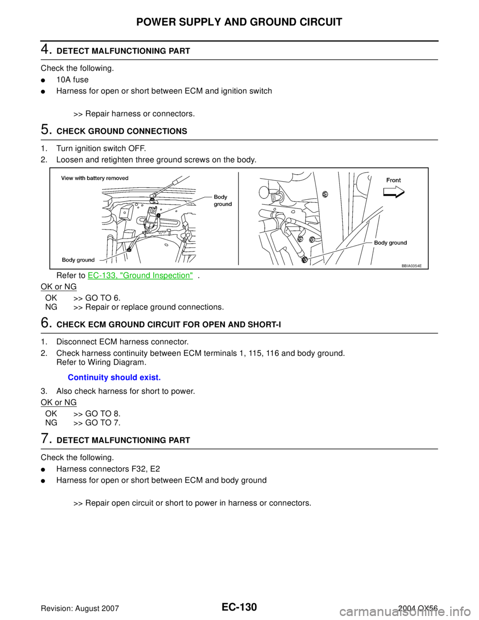
5. CHECK GROUND CONNECTIONS
1. Turn ignition switch OFF.
2. Loosen and retighten three ground screws on the body.
Refer to EC-133, "
Ground Inspection" .
OK or NG
OK >> GO TO 6.
NG >> Repair or replace ground connections.
6. CHECK ECM GROUND CIRCUIT FOR OPEN AND SHORT-I
1. Disconnect ECM harness connector.
2. Check harness continuity between ECM terminals 1, 115, 116 and body ground.
Refer to Wiring Diagram.
3. Also check harness for short to power.
OK or NG
OK >> GO TO 8.
NG >> GO TO 7.
7. DETECT MALFUNCTIONING PART
Check the following.
�Harness connectors F32, E2
�Harness for open or short between ECM and body ground
>> Repair open circuit or short to power in harness or connectors.
BBIA0354E
Continuity should exist.
Page 1323 of 3371

EC-132Revision: August 2007
POWER SUPPLY AND GROUND CIRCUIT
2004 QX56
11 . CHECK ECM POWER SUPPLY CIRCUIT-V
1. Disconnect ECM harness connector.
2. Disconnect IPDM E/R harness connector E119.
3. Check harness continuity between ECM terminals 119, 120 and IPDM E/R terminal 3.
Refer to Wiring Diagram.
4. Also check harness for short to ground and short to power.
OK or NG
OK >> GO TO 14.
NG >> Repair open circuit or short to ground or short to power in harness or connectors.
12. CHECK ECM POWER SUPPLY CIRCUIT-VI
1. Disconnect ECM harness connector.
2. Disconnect IPDM E/R harness connector E119.
3. Check harness continuity between ECM terminal 111 and IPDM E/R terminal 7.
Refer to Wiring Diagram.
4. Also check harness for short to ground and short to power.
OK or NG
OK >> GO TO 13.
NG >> Repair open circuit or short to ground or short to power in harness or connectors.
13. CHECK 20A FUSE
Check 20A fuse (No. 53, located in the IPDM E/R).
OK or NG
OK >> GO TO 17.
NG >> Replace 20A fuse.
14. CHECK GROUND CONNECTIONS
1. Turn ignition switch OFF.
2. Loosen and retighten three ground screws on the body.
Refer to EC-133, "
Ground Inspection" .
OK or NG
OK >> GO TO 15.
NG >> Repair or replace ground connections.Continuity should exist.
Continuity should exist.
BBIA0354E
Page 1342 of 3371
DTC P0101 MAF SENSOR
EC-151
C
D
E
F
G
H
I
J
K
L
MA
EC
Revision: August 20072004 QX56
3. RETIGHTEN GROUND SCREWS
1. Turn ignition switch OFF.
2. Loosen and retighten three ground screws on the body.
Refer to EC-133, "
Ground Inspection" .
OK or NG
OK >> GO TO 4.
NG >> Repair or replace ground connections.
4. CHECK MAF SENSOR POWER SUPPLY CIRCUIT
1. Disconnect mass air flow (MAF) sensor harness connector.
2. Turn ignition switch ON.
3. Check voltage between MAF sensor terminal 2 and ground with
CONSULT-II or tester.
OK or NG
OK >> GO TO 6.
NG >> GO TO 5.
5. DETECT MALFUNCTIONING PART
Check the following.
�Harness connectors E2, F32
�Harness for open or short between IPDM E/R and mass air flow sensor
�Harness for open or short between mass air flow sensor and ECM
>> Repair harness or connectors.
BBIA0354E
BBIA0368E
Voltage: Battery voltage
PBIB11 68 E
Page 1349 of 3371
EC-158Revision: August 2007
DTC P0102, P0103 MAF SENSOR
2004 QX56
3. RETIGHTEN GROUND SCREWS
1. Turn ignition switch OFF.
2. Loosen and retighten three ground screws on the body.
Refer to EC-133, "
Ground Inspection" .
OK or NG
OK >> GO TO 4.
NG >> Repair or replace ground connections.
4. CHECK MAF SENSOR POWER SUPPLY CIRCUIT
1. Disconnect mass air flow (MAF) sensor harness connector.
2. Turn ignition switch ON.
3. Check voltage between MAF sensor terminal 2 and ground with
CONSULT-II or tester.
OK or NG
OK >> GO TO 6.
NG >> GO TO 5.
5. DETECT MALFUNCTIONING PART
Check the following.
�Harness connectors E2, F32
�Harness for open or short between IPDM E/R and mass air flow sensor
�Harness for open or short between mass air flow sensor and ECM
>> Repair harness or connectors.
BBIA0354E
BBIA0368E
Voltage: Battery voltage
PBIB11 68 E
Page 1354 of 3371
DTC P0112, P0113 IAT SENSOR
EC-163
C
D
E
F
G
H
I
J
K
L
MA
EC
Revision: August 20072004 QX56
Diagnostic ProcedureUBS00H1G
1. CHECK GROUND CONNECTIONS
1. Turn ignition switch OFF.
2. Loosen and retighten three ground screws on the body.
Refer to EC-133, "
Ground Inspection" .
OK or NG
OK >> GO TO 2.
NG >> Repair or replace ground connections.
2. CHECK INTAKE AIR TEMPERATURE SENSOR POWER SUPPLY CIRCUIT
1. Disconnect mass air flow sensor (intake air temperature sensor
is built-into) harness connector.
2. Turn ignition switch ON.
3. Check voltage between mass air flow sensor terminal 5 and
ground.
OK or NG
OK >> GO TO 3.
NG >> Repair harness or connectors.
BBIA0354E
BBIA0368E
Voltage: Approximately 5V
PBIB11 69 E