Page 1966 of 2643

6E – 12ISTEERING WHEEL AND COLUMN
DAEWOO V–121 BL4
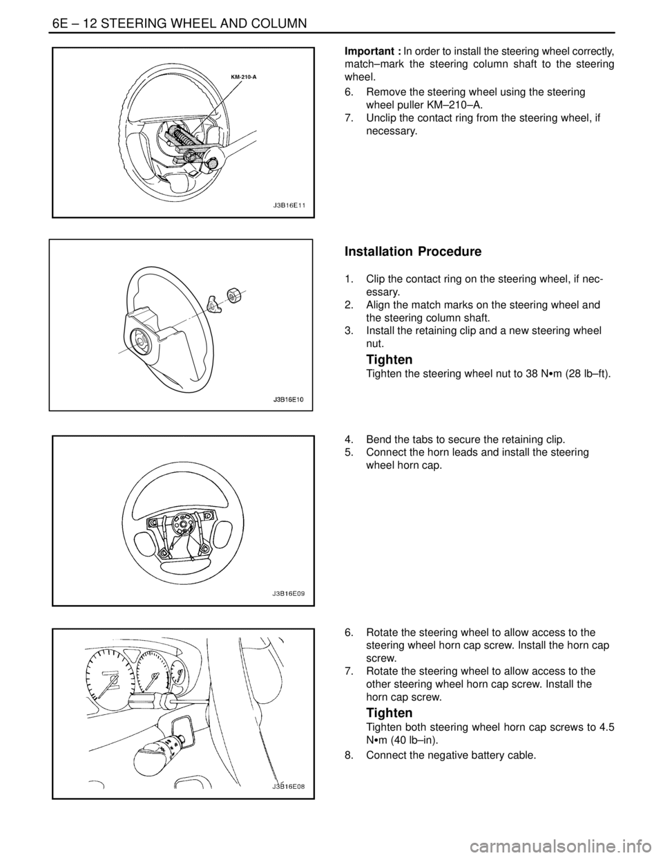
Important : In order to install the steering wheel correctly,
match–mark the steering column shaft to the steering
wheel.
6. Remove the steering wheel using the steering
wheel puller KM–210–A.
7. Unclip the contact ring from the steering wheel, if
necessary.
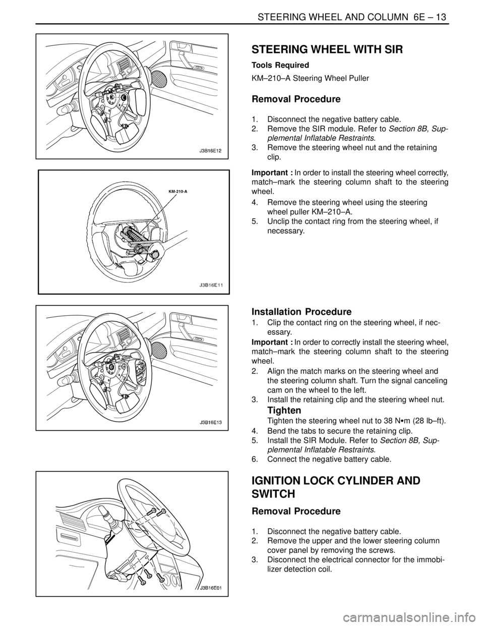
Installation Procedure
1. Clip the contact ring on the steering wheel, if nec-
essary.
2. Align the match marks on the steering wheel and
the steering column shaft.
3. Install the retaining clip and a new steering wheel
nut.
Tighten
Tighten the steering wheel nut to 38 NSm (28 lb–ft).
4. Bend the tabs to secure the retaining clip.
5. Connect the horn leads and install the steering
wheel horn cap.
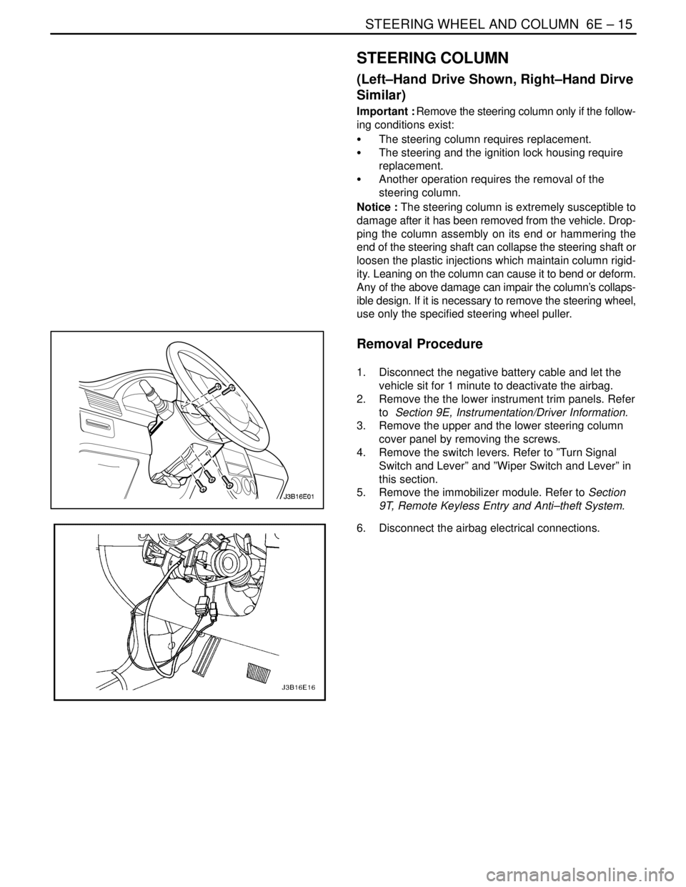
6. Rotate the steering wheel to allow access to the
steering wheel horn cap screw. Install the horn cap
screw.
7. Rotate the steering wheel to allow access to the
other steering wheel horn cap screw. Install the
horn cap screw.
Tighten
Tighten both steering wheel horn cap screws to 4.5
NSm (40 lb–in).
8. Connect the negative battery cable.
Page 1967 of 2643

STEERING WHEEL AND COLUMN 6E – 13
DAEWOO V–121 BL4
STEERING WHEEL WITH SIR
Tools Required
KM–210–A Steering Wheel Puller
Removal Procedure
1. Disconnect the negative battery cable.
2. Remove the SIR module. Refer to Section 8B, Sup-
plemental Inflatable Restraints.
3. Remove the steering wheel nut and the retaining
clip.
Important : In order to install the steering wheel correctly,
match–mark the steering column shaft to the steering
wheel.
4. Remove the steering wheel using the steering
wheel puller KM–210–A.
5. Unclip the contact ring from the steering wheel, if
necessary.
Installation Procedure
1. Clip the contact ring on the steering wheel, if nec-
essary.
Important : In order to correctly install the steering wheel,
match–mark the steering column shaft to the steering
wheel.
2. Align the match marks on the steering wheel and
the steering column shaft. Turn the signal canceling
cam on the wheel to the left.
3. Install the retaining clip and the steering wheel nut.
Tighten
Tighten the steering wheel nut to 38 NSm (28 lb–ft).
4. Bend the tabs to secure the retaining clip.
5. Install the SIR Module. Refer to Section 8B, Sup-
plemental Inflatable Restraints.
6. Connect the negative battery cable.
IGNITION LOCK CYLINDER AND
SWITCH
Removal Procedure
1. Disconnect the negative battery cable.
2. Remove the upper and the lower steering column
cover panel by removing the screws.
3. Disconnect the electrical connector for the immobi-
lizer detection coil.
Page 1968 of 2643
6E – 14ISTEERING WHEEL AND COLUMN
DAEWOO V–121 BL4
4. With the key in the ignition turned to the position
designated ACC, remove the lock cylinder by
pressing down the detent spring and pulling the
lock cylinder out of the switch cylinder housing.
5. Remove the ignition switch retaining screw.
6. Disconnect the wiring and remove the ignition
switch.
Installation Procedure
1. Install the ignition switch with the ignition switch
retaining screw.
Tighten
Tighten the ignition switch retaining screw to 2.5 NSm
(22 lb–in).
2. Connect the wiring to the ignition switch.
3. Install the lock cylinder.
4. Connect the electrical connector for the immobilizer
detection unit.
5. Install the upper and the lower steering column cov-
er panel with the screws.
Tighten
Tighten the upper and the lower steering column cov-
er panel screws to 2.5 NSm (22 lb–in).
6. Connect the negative battery cable.
Page 1969 of 2643

STEERING WHEEL AND COLUMN 6E – 15
DAEWOO V–121 BL4
STEERING COLUMN
(Left–Hand Drive Shown, Right–Hand Dirve
Similar)
Important : Remove the steering column only if the follow-
ing conditions exist:
S The steering column requires replacement.
S The steering and the ignition lock housing require
replacement.
S Another operation requires the removal of the
steering column.
Notice : The steering column is extremely susceptible to
damage after it has been removed from the vehicle. Drop-
ping the column assembly on its end or hammering the
end of the steering shaft can collapse the steering shaft or
loosen the plastic injections which maintain column rigid-
ity. Leaning on the column can cause it to bend or deform.
Any of the above damage can impair the column’s collaps-
ible design. If it is necessary to remove the steering wheel,
use only the specified steering wheel puller.
Removal Procedure
1. Disconnect the negative battery cable and let the
vehicle sit for 1 minute to deactivate the airbag.
2. Remove the the lower instrument trim panels. Refer
to Section 9E, Instrumentation/Driver Information.
3. Remove the upper and the lower steering column
cover panel by removing the screws.
4. Remove the switch levers. Refer to ”Turn Signal
Switch and Lever” and ”Wiper Switch and Lever” in
this section.
5. Remove the immobilizer module. Refer to Section
9T, Remote Keyless Entry and Anti–theft System.
6. Disconnect the airbag electrical connections.
Page 1972 of 2643
6E – 18ISTEERING WHEEL AND COLUMN
DAEWOO V–121 BL4
6. Connect the ignition switch electrical connection.
7. Connect the airbag electrical connections.
8. Install the switch levers. Refer to ”Turn Signal
Switch and Lever” and ”Wiper Switch and Lever” in
this section.
9. Install the immobilizer module. Refer to Section 9T,
Remote Keyless Entry and Anti–theft System.
10. Install the lower instrument trim panels. Refer to
Section 9E, Instrumentation/Driver Information.
11. Install the upper and the lower steering column cov-
er panel with the screws..
Tighten
Tighten the upper and the lower steering column pan-
el screws to 2.5 NSm (22 lb–in).
12. Inspect the steering wheel in a straight–ahead posi-
tion. Refer to Section 6C, Power Steering Gear.
13. Connect the negative battery cable.
Page 1975 of 2643

SECTION : 7A
HEATING AND VENTILATION SYSTEM
CAUTION : Disconnect the negative battery cable before removing or installing any electrical unit or when a tool
or equipment could easily come in contact with exposed electrical terminals. Disconnecting this cable will help
prevent personal injury and damage to the vehicle. The ignition must also be in LOCK unless otherwise noted.
TABLE OF CONTENTS
SPECIFICATIONS7A–1 . . . . . . . . . . . . . . . . . . . . . . . . . .
Heater Temperature Specifications 7A–1. . . . . . . . . . .
Fastener Tightening Specifications 7A–1. . . . . . . . . . .
SCHEMATIC AND ROUTING DIAGRAMS7A–3 . . . . .
Non–A/C Diagrams 7A–3. . . . . . . . . . . . . . . . . . . . . . . .
Airflow – Typical 7A–4. . . . . . . . . . . . . . . . . . . . . . . . . . .
Airflow with Rear Heating Duct 7A–5. . . . . . . . . . . . . .
DIAGNOSIS7A–6 . . . . . . . . . . . . . . . . . . . . . . . . . . . . . . . .
HEATER SYSTEM 7A–6. . . . . . . . . . . . . . . . . . . . . . . . . .
Insufficient Heating or Defrosting 7A–6. . . . . . . . . . . . .
Blower Electrical 7A–9. . . . . . . . . . . . . . . . . . . . . . . . . . .
Improper Air delivery or No Mode Shift 7A–11. . . . . .
Too Much Heat 7A–13. . . . . . . . . . . . . . . . . . . . . . . . . . .
Controls 7A–15. . . . . . . . . . . . . . . . . . . . . . . . . . . . . . . . .
Blower Noise 7A–16. . . . . . . . . . . . . . . . . . . . . . . . . . . . . MAINTENANCE AND REPAIR7A–18 . . . . . . . . . . . . . .
ON–VEHICLE SERVICE 7A–18. . . . . . . . . . . . . . . . . . . .
Temperature Cable Adjustment 7A–18. . . . . . . . . . . . .
Temperature Control Cable 7A–18. . . . . . . . . . . . . . . . .
Control Assembly 7A–20. . . . . . . . . . . . . . . . . . . . . . . . .
Control Assembly Knob Lighting 7A–21. . . . . . . . . . . .
Heater/Air Distributor Case Assembly 7A–21. . . . . . .
Blower Motor 7A–23. . . . . . . . . . . . . . . . . . . . . . . . . . . . .
High–Blower Relay 7A–24. . . . . . . . . . . . . . . . . . . . . . . .
Blower Resistor 7A–25. . . . . . . . . . . . . . . . . . . . . . . . . .
Heater Hoses 7A–25. . . . . . . . . . . . . . . . . . . . . . . . . . . .
Heater Core 7A–26. . . . . . . . . . . . . . . . . . . . . . . . . . . . . .
GENERAL DESCRIPTION AND SYSTEM
OPERATION7A–28 . . . . . . . . . . . . . . . . . . . . . . . . . . . . .
Heating and Ventilation Systems 7A–28. . . . . . . . . . . .
SPECIFICATIONS
HEATER TEMPERATURE SPECIFICATIONS
Ambient Air TemperatureHeater Outlet Air Temperature
–18°C (0°F)54°C (129°F)
– 4°C (25°F)59°C (138°F)
10°C (50°F)64°C (147°F)
24°C (75°F)68°C (154°F)
FASTENER TIGHTENING SPECIFICATIONS
ApplicationNSmLb–FtLb–In
Blower Motor–to–A/C Assembly Screws1.2–11
Blower Motor Resistor Screws1.2–11
Blower Motor Retaining Screws1.2–11
Controller Retaining Screws2–18
Heater/Air Distributor Case Assembly Screw4–35
Page 1985 of 2643

HEATING AND VENTILATION SYSTEM 7A – 11
DAEWOO V–121 BL4
StepNo Yes Value(s) Action
211. Disconnect the resistor block connector.
2. Connect one lead of a self–powered test light
to any single lead on the resistor block. Use
the other lead to probe each of the other two
terminals.
Does the test light illuminate on all terminals?–Go to Step 23Go to Step 22
22Replace the resistor block.
Is the repair complete?–System OK–
231. Turn the ignition to LOCK.
2. Disconnect the connector from the resistor
block.
3. Connect a jumper lead from the positive termi-
nal on the battery to any wire terminal in the
connector.
4. Use a 12–volt test light to check for voltage
from the corresponding wire on the blower
speed switch.
5. Repeat the same test on the other wires.
Does the lamp light on all three wires?–Go to Step 25Go to Step 24
24Replace the blower speed switch.
Is the repair complete?–System OK–
25Repair the open in the affected wire.
Is the repair complete?–System OK–
IMPROPER AIR DELIVERY OR NO MODE SHIFT
This procedure provides a test of all functions of the heater/defroster unit.
1. Warm up the vehicle.
2. Keep the engine running.
3. Perform the tests outlined in the table below and look for the results indicated.
CONTROL SETTINGS
CORRECT RESULTS
Mode
KnobTe m p
Contro
lBlower
Motor
SwitchBlower
SpeedPower
Vent
OutletFloor
OutletDefrost
OutletSide
Window
Outlet
VentColdOffOffNo
AirflowNo
AirflowNo
AirflowNo
Airflow
VentCold4HighAmbient
AirflowNo
AirflowNo
AirflowNo
Airflow
FloorCold to
Hot4HighNo
AirflowCold to Hot
AirflowMinimum
Cold to Hot
AirflowMinimum
Cold to Hot
Airflow
De-
frosterCold to
Hot4HighNo
AirflowMinimum
Cold to Hot
AirflowCold to Hot
AirflowMinimum
Cold to Hot
Airflow
If any of these settings does not produce the correct results, perform the following diagnostic procedure.
Page 1992 of 2643
7A – 18IHEATING AND VENTILATION SYSTEM
DAEWOO V–121 BL4
MAINTENANCE AND REPAIR
ON–VEHICLE SERVICE
TEMPERATURE CABLE
ADJUSTMENT
Because the cable and the cable housings have fixed
lengths, it is impossible to make a temperature cable ad-
justment.
In addition, the heater/air distributor case linkage cannot
be adjusted.
If a malfunction is suspected, verify the proper operation
of the controller and the mechanical doors for the heater/
air distributor case assembly.
TEMPERATURE CONTROL CABLE
(Left–Hand Drive Shown, Right–Hand Drive
Similar)
Removal Procedure
1. Disconnect the negative battery cable.
2. Remove the center molding. Refer toSection 9E,
Instrumentation/Driver Information.
3. Disconnect the mode control cable from the mode
door.
4. Disconnect the temperature control cable eyelet
from the post on the controller.
5. Pry off the clip of the temperature control cable.