Page 1695 of 2643
AISIN AUTOMATIC TRANSAXLE 5A2 – 105
DAEWOO V–121 BL4
4. Connect the shift control cable to the TR switch.
5. Install the shift control cable retaining E–ring.
6. Connect the shift control cable to the shift control
lever assembly.
7. Install the cable adjusting nut.
Tighten
Tighten the cable adjusting nut to 8 NSm (71 Ib–in).
8. Install the trim panel to the floor console. Refer to
Section 9G, Interior Trim.
9. Connect the negative battery cable.
SHIFT SELECT COVER
Removal Procedure
1. Disconnect the negative battery cable.
2. Remove the floor console. Refer to Section 9G,
Interior Trim.
3. Remove the shift select lever knob.
4. Disconnect the connectors.
5. Remove the shift select cover from the shift select
housing.
Page 1696 of 2643
5A2 – 106IAISIN AUTOMATIC TRANSAXLE
DAEWOO V–121 BL4
Installation Procedure
1. Connect the connectors to the shift select cover.
2. Install the shift select cover to the housing.
3. Install the shift select lever knob.
4. Install the floor console. Refer to Section 9G, Interi-
or Trim.
5. Connect the negative battery cable.
INPUT SHAFT SPEED (ISS) SENSOR
Removal Procedure
1. Disconnect the negative battery cable.
2. Disconnect the input shaft speed (ISS) sensor elec-
trical connector.
3. Remove the ISS sensor retaining bolt.
4. Remove the ISS sensor from the transaxle.
Page 1697 of 2643
AISIN AUTOMATIC TRANSAXLE 5A2 – 107
DAEWOO V–121 BL4
Installation Procedure
Notice : Lubricate the O–ring with ISU DEXRON III.
1. Install a new O–ring on the ISS sensor.
2. Install the ISS sensor and retaining bolt into the
transaxle case.
Tighten
Tighten the ISS sensor retaining bolt to 5.4 NSm (48
Ib–in).
3. Connect the ISS sensor electrical connector.
4. Connect the negative battery cable.
OUTPUT SHAFT SPEED (OSS)
SENSOR
Removal Procedure
1. Disconnect the negative battery cable.
2. Disconnect the output shaft speed (OSS) sensor
electrical connector.
3. Remove the OSS sensor retaining bolt.
4. Remove the OSS sensor from the transaxle.
Page 1698 of 2643
5A2 – 108IAISIN AUTOMATIC TRANSAXLE
DAEWOO V–121 BL4
Installation Procedure
Notice : Lubricate the O–ring with ISU DEXRON III.
1. Install a new O–ring on the output shaft speed
(OSS) sensor.
2. Install the OSS sensor and retaining bolt into the
transaxle.
Tighten
Tighten the OSS sensor retaining bolt to 7.4 NSm (65
Ib–in).
3. Connect the OSS sensor electrical connector.
4. Connect the negative battery cable.
TRANSMISSION CONTROL MODULE
(TCM)
Removal Procedure
1. Disconnect the negative battery cable.
2. Disconnect the transmission control module (TCM)
electrical connector.
3. Remove the TCM retaining bolts.
4. Remove the TCM.
Page 1699 of 2643
AISIN AUTOMATIC TRANSAXLE 5A2 – 109
DAEWOO V–121 BL4
Installation Procedure
1. Connect the negative battery cable.
2. Install the TCM and retaining bolts.
Tighten
Tighten the TCM retaining bolts to 5 NSm (44 Ib–in).
3. Connect the TCM electrical connector.
4. Connect the negative battery cable.
FLUID COOLER INLET PIPES AND
HOSES
Removal Procedure
1. Raise and support the vehicle.
2. Drain the transaxle fluid.
3. Remove the clip from the hose, then disconnect the
hose from the fluid cooler inlet pipe.
4. Remove the inlet pipe union bolt from the radiator.
5. Remove the fluid cooler inlet pipe bolt from the
transaxle.
6. Remove the inlet pipe fitting nut from the transaxle.
7. Remove the fluid cooler inlet pipe and hoses.
Page 1701 of 2643

AISIN AUTOMATIC TRANSAXLE 5A2 – 111
DAEWOO V–121 BL4
Installation Procedure
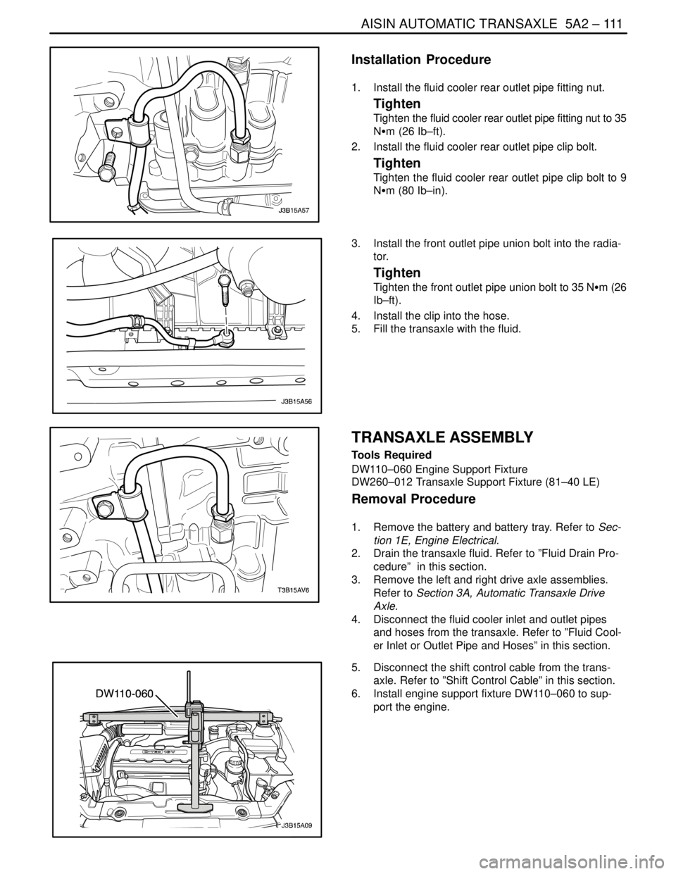
1. Install the fluid cooler rear outlet pipe fitting nut.
Tighten
Tighten the fluid cooler rear outlet pipe fitting nut to 35
NSm (26 Ib–ft).
2. Install the fluid cooler rear outlet pipe clip bolt.
Tighten
Tighten the fluid cooler rear outlet pipe clip bolt to 9
NSm (80 Ib–in).
3. Install the front outlet pipe union bolt into the radia-
tor.
Tighten
Tighten the front outlet pipe union bolt to 35 NSm (26
Ib–ft).
4. Install the clip into the hose.
5. Fill the transaxle with the fluid.
TRANSAXLE ASSEMBLY
Tools Required
DW110–060 Engine Support Fixture
DW260–012 Transaxle Support Fixture (81–40 LE)
Removal Procedure
1. Remove the battery and battery tray. Refer to Sec-
tion 1E, Engine Electrical.
2. Drain the transaxle fluid. Refer to ”Fluid Drain Pro-
cedure” in this section.
3. Remove the left and right drive axle assemblies.
Refer to Section 3A, Automatic Transaxle Drive
Axle.
4. Disconnect the fluid cooler inlet and outlet pipes
and hoses from the transaxle. Refer to ”Fluid Cool-
er Inlet or Outlet Pipe and Hoses” in this section.
5. Disconnect the shift control cable from the trans-
axle. Refer to ”Shift Control Cable” in this section.
6. Install engine support fixture DW110–060 to sup-
port the engine.
Page 1706 of 2643
5A2 – 116IAISIN AUTOMATIC TRANSAXLE
DAEWOO V–121 BL4
15. Connect the fluid cooler inlet and outlet pipe and
hose into the transaxle. Refer to ”Fluid Cooler Inlet
or Outlet Pipe and Hoses” in this section.
16. Install the left and right drive axle assemblies. Refer
to Section 3A, Automatic Transaxle Drive Axle.
17. Install the battery and battery tray. Refer to Section
1E, Engine Electrical.
18. Fill the transaxle with fluid. Refer to ”Fluid Drain
Procedure” in this section.
19. Check the fluid level. Refer to ”Transaxle Fluid Lev-
el Checking Procedure” in this section.
Page 1809 of 2643

AISIN AUTOMATIC TRANSAXLE 5A2 – 219
DAEWOO V–121 BL4
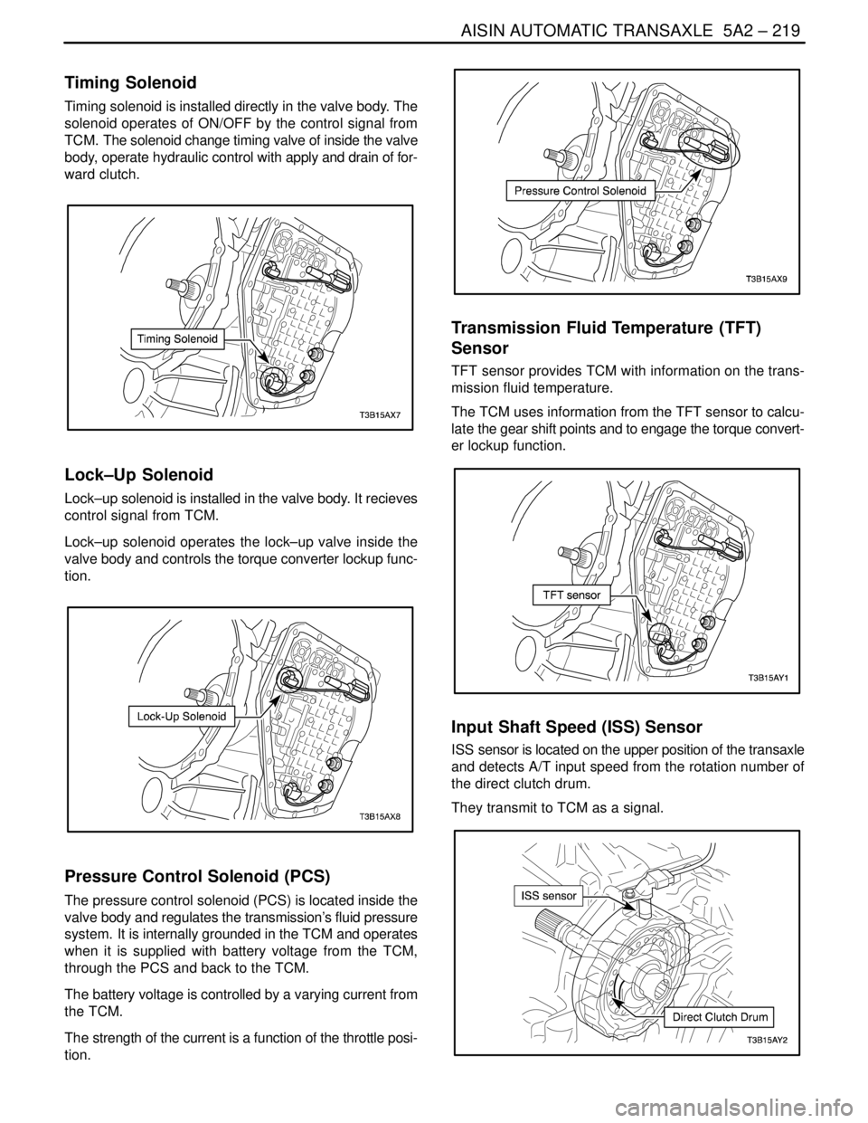
Timing Solenoid
Timing solenoid is installed directly in the valve body. The
solenoid operates of ON/OFF by the control signal from
TCM. The solenoid change timing valve of inside the valve
body, operate hydraulic control with apply and drain of for-
ward clutch.
Lock–Up Solenoid
Lock–up solenoid is installed in the valve body. It recieves
control signal from TCM.
Lock–up solenoid operates the lock–up valve inside the
valve body and controls the torque converter lockup func-
tion.
Pressure Control Solenoid (PCS)
The pressure control solenoid (PCS) is located inside the
valve body and regulates the transmission’s fluid pressure
system. It is internally grounded in the TCM and operates
when it is supplied with battery voltage from the TCM,
through the PCS and back to the TCM.
The battery voltage is controlled by a varying current from
the TCM.
The strength of the current is a function of the throttle posi-
tion.
Transmission Fluid Temperature (TFT)
Sensor
TFT sensor provides TCM with information on the trans-
mission fluid temperature.
The TCM uses information from the TFT sensor to calcu-
late the gear shift points and to engage the torque convert-
er lockup function.
Input Shaft Speed (ISS) Sensor
ISS sensor is located on the upper position of the transaxle
and detects A/T input speed from the rotation number of
the direct clutch drum.
They transmit to TCM as a signal.