Page 1928 of 2643
POWER STEERING GEAR 6C – 11
DAEWOO V–121 BL4
MAINTENANCE AND REPAIR
ON–VEHICLE SERVICE
RACK AND PINION ASSEMBLY
(Left–Hand Drive Shown, Right–Hand Drive
Similar)
Tools Required
KM–507–B Ball Joint Remover
Removal Procedure
1. Disconnect the negative battery cable.
2. Raise and suitably support the vehicle.
3. Remove the wheels. Refer to Section 2E, Tires and
Wheels.
4. Disconnect the power steering gear fluid outlet
pipe. Place a drain pan under the steering gear to
catch the power steering fluid.
5. Disconnect the power steering gear fluid inlet pipe.
6. Position the steering gear straight ahead by turning
the steering wheel until the steering wheel spokes
are vertical and pointed to the left.
7. Scribe a mark on the stub shaft housing that lines
up with a mark on the intermediate shaft lower cou-
pling.
8. Remove the intermediate shaft pinch bolt.
Page 1931 of 2643

6C – 14IPOWER STEERING GEAR
DAEWOO V–121 BL4
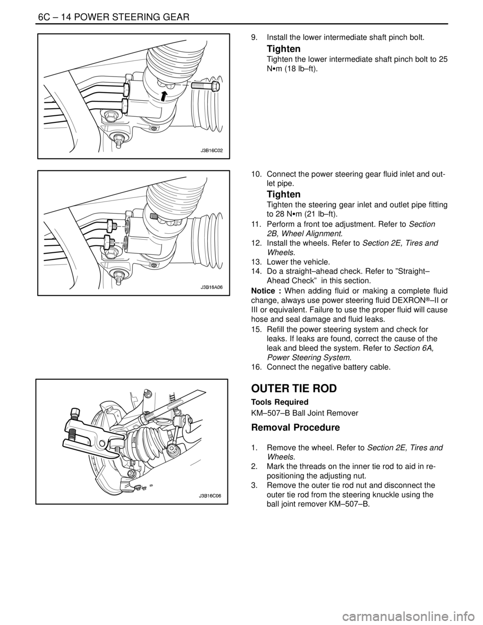
9. Install the lower intermediate shaft pinch bolt.
Tighten
Tighten the lower intermediate shaft pinch bolt to 25
NSm (18 lb–ft).
10. Connect the power steering gear fluid inlet and out-
let pipe.
Tighten
Tighten the steering gear inlet and outlet pipe fitting
to 28 NSm (21 lb–ft).
11. Perform a front toe adjustment. Refer to Section
2B, Wheel Alignment.
12. Install the wheels. Refer to Section 2E, Tires and
Wheels.
13. Lower the vehicle.
14. Do a straight–ahead check. Refer to ”Straight–
Ahead Check” in this section.
Notice : When adding fluid or making a complete fluid
change, always use power steering fluid DEXRON®–II or
III or equivalent. Failure to use the proper fluid will cause
hose and seal damage and fluid leaks.
15. Refill the power steering system and check for
leaks. If leaks are found, correct the cause of the
leak and bleed the system. Refer to Section 6A,
Power Steering System.
16. Connect the negative battery cable.
OUTER TIE ROD
Tools Required
KM–507–B Ball Joint Remover
Removal Procedure
1. Remove the wheel. Refer to Section 2E, Tires and
Wheels.
2. Mark the threads on the inner tie rod to aid in re-
positioning the adjusting nut.
3. Remove the outer tie rod nut and disconnect the
outer tie rod from the steering knuckle using the
ball joint remover KM–507–B.
Page 1938 of 2643
POWER STEERING GEAR 6C – 21
DAEWOO V–121 BL4
6. Fill the fluid reservoir with power steering fluid.
7. Inspect for leaks. If there are leaks, correct the
cause of the leaks and bleed the system. Refer to
”Bleeding the Power Steering System” in this sec-
tion.
SPEED SENSITIVE POWER
STEERING CONTROL MODULE
Removal Procedure
1. Disconnect negative battery cable.
2. Remove the glove box. Refer to Section 9G, Interi-
or Trim.
3. Slide the speed sensitive power steering (SSPS)
control module off from the control module bracket.
4. Disconnect the electrical connector from the SSPS
control module.
Installation Procedure
1. Connect the electrical connector to the SSPS con-
trol module.
2. Slide the SSPS control module onto the SSPS con-
trol module bracket.
3. Install the ashtray. Refer to Section 9G, Interior
Trim.
4. Connect the negative battery cable.
Page 1955 of 2643

SECTION : 6E
STEERING WHEEL AND COLUMN
CAUTION : Disconnect the negative battery cable before removing or installing any electrical unit or when a tool
or equipment could easily come in contact with exposed electrical terminals. Disconnecting this cable will help
prevent personal injury and damage to the vehicle. The ignition must also be in LOCK unless otherwise noted.
TABLE OF CONTENTS
SPECIFICATIONS6E–1 . . . . . . . . . . . . . . . . . . . . . . . . . .
Fastener Tightening Specifications 6E–1. . . . . . . . . . .
SPECIAL TOOLS6E–2 . . . . . . . . . . . . . . . . . . . . . . . . . . .
Special Tools Table 6E–2. . . . . . . . . . . . . . . . . . . . . . . .
DIAGNOSIS6E–2 . . . . . . . . . . . . . . . . . . . . . . . . . . . . . . . .
Steering Column Diagnosis 6E–2. . . . . . . . . . . . . . . . .
MAINTENANCE AND REPAIR6E–8 . . . . . . . . . . . . . . .
ON–VEHICLE SERVICE 6E–8. . . . . . . . . . . . . . . . . . . . .
Headlamp/Turn Signal Switch and Lever 6E–8. . . . . .
Wiper Switch and Lever 6E–9. . . . . . . . . . . . . . . . . . . . Steering Wheel Rotation Sensor 6E–10. . . . . . . . . . . .
Steering Wheel Without SIR 6E–11. . . . . . . . . . . . . . . .
Steering Wheel With SIR 6E–13. . . . . . . . . . . . . . . . . .
Ignition Lock Cylinder and Switch 6E–13. . . . . . . . . . .
Steering Column 6E–15. . . . . . . . . . . . . . . . . . . . . . . . . .
UNIT REPAIR 6E–19. . . . . . . . . . . . . . . . . . . . . . . . . . . . .
Tilt Steering Column 6E–19. . . . . . . . . . . . . . . . . . . . . .
GENERAL DESCRIPTION AND SYSTEM
OPERATION6E–20 . . . . . . . . . . . . . . . . . . . . . . . . . . . . .
Steering Wheel and Column 6E–20. . . . . . . . . . . . . . . .
Ignition Key Reminder 6E–20. . . . . . . . . . . . . . . . . . . . .
SPECIFICATIONS
FASTENER TIGHTENING SPECIFICATIONS
ApplicationNSmLb–FtLb–In
Ignition Switch Housing Shear Bolts11–97
Ignition Switch Retaining Screw2.5–22
Steering Column Jacket Assembly Front Bracket Bolts2216–
Steering Column Jacket Assembly Rear Bracket Nuts2216–
Steering Shaft Universal Joint Pinch Bolt2518–
Steering Wheel Horn Cap Screws4.5–40
Steering Wheel Nut3828–
Steering Wheel Rotation Sensor Retaining Screw2–18
Support Housing Screws1612–
Turn Signal Switch Housing Screws3–27
Upper and Lower Steering Column Cover Panel Screws2.5–22
Page 1962 of 2643
6E – 8ISTEERING WHEEL AND COLUMN
DAEWOO V–121 BL4
MAINTENANCE AND REPAIR
ON–VEHICLE SERVICE
HEADLAMP/TURN SIGNAL SWITCH
AND LEVER
(Left–Hand Drive Shown, Right–Hand Dirve
Similar)
Removal Procedure
1. Disconnect the negative battery cable.
2. Remove the upper and the lower steering column
cover panel screws.
3. Remove the upper and the lower steering column
cover panels.
4. Remove the turn signal switch by pushing the tabs
on the top and the bottom of the switch housing.
5. Disconnect the electrical connections from the turn
signal switch.
Installation Procedure
1. Connect the electrical connections to the turn signal
switch.
2. Install the turn signal switch by snapping it into the
switch housing.
Page 1963 of 2643

STEERING WHEEL AND COLUMN 6E – 9
DAEWOO V–121 BL4
3. Install the upper and the lower steering column cov-
er panels. Install the upper and the lower steering
column cover panel screws.
Tighten
Tighten the upper and the lower steering column cov-
er panel screws to 2.5 NSm (22 lb–in).
4. Connect the negative battery cable.
WIPER SWITCH AND LEVER
(Left–Hand Drive Shown, Right–Hand Dirve
Similar)
Removal Procedure
1. Disconnect the negative battery cable.
2. Remove the upper and the lower steering column
cover panel screws.
3. Remove the upper and the lower steering column
cover panels.
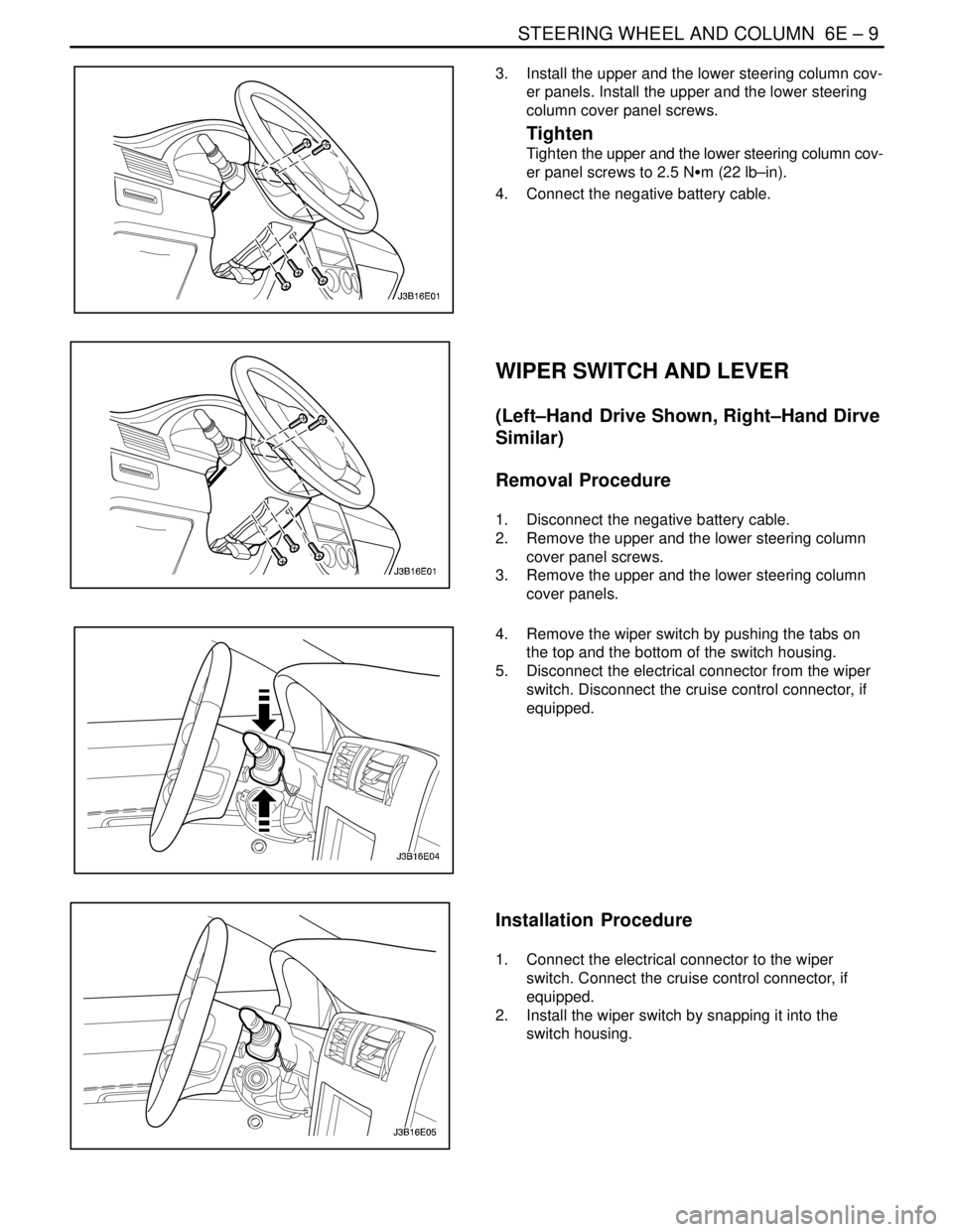
4. Remove the wiper switch by pushing the tabs on
the top and the bottom of the switch housing.
5. Disconnect the electrical connector from the wiper
switch. Disconnect the cruise control connector, if
equipped.
Installation Procedure
1. Connect the electrical connector to the wiper
switch. Connect the cruise control connector, if
equipped.
2. Install the wiper switch by snapping it into the
switch housing.
Page 1964 of 2643

6E – 10ISTEERING WHEEL AND COLUMN
DAEWOO V–121 BL4
3. Install the upper and the lower steering column cov-
er panels. Install the upper and the lower steering
column cover panel screws.
Tighten
Tighten the upper and the lower steering column cov-
er panel screws to 2.5 NSm (22 lb–in).
4. Connect the negative battery cable.
STEERING WHEEL ROTATION
SENSOR
(Left–Hand Drive Shown, Right–Hand Dirve
Similar)
Removal Procedure
1. Disconnect the negative battery cable.
2. Remove the upper and the lower instrument trim
panels. Refer to Section 9E, Instrumentation/Driver
Information.
3. Disconnect the steering wheel rotation sensor elec-
trical connector.
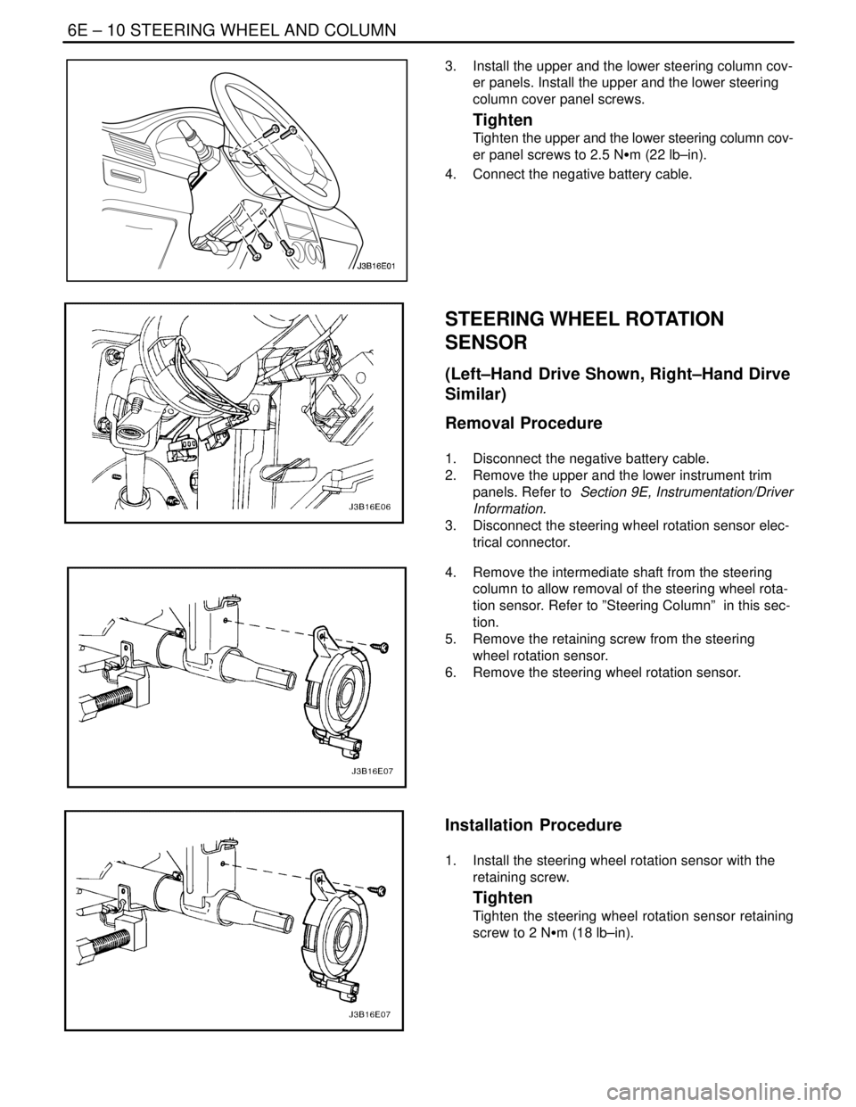
4. Remove the intermediate shaft from the steering
column to allow removal of the steering wheel rota-
tion sensor. Refer to ”Steering Column” in this sec-
tion.
5. Remove the retaining screw from the steering
wheel rotation sensor.
6. Remove the steering wheel rotation sensor.
Installation Procedure
1. Install the steering wheel rotation sensor with the
retaining screw.
Tighten
Tighten the steering wheel rotation sensor retaining
screw to 2 NSm (18 lb–in).
Page 1965 of 2643
STEERING WHEEL AND COLUMN 6E – 11
DAEWOO V–121 BL4
2. Install the intermediate shaft onto the steering col-
umn. Refer to ”Steering Column” in this section.
3. Connect the steering wheel rotation sensor electri-
cal connector.
4. Install the upper and the lower instrument trim pan-
els. Refer to Section 9E, Instrumentation/Driver
Information.
5. Connect the negative battery cable.
STEERING WHEEL WITHOUT SIR
Tools Required
KM–210–A Steering Wheel Puller
Removal Procedure
1. Disconnect the negative battery cable.
2. Rotate the steering wheel to allow access to the
steering wheel horn cap screw. Remove the horn
cap screw.
3. Rotate the steering wheel to allow access to the
other steering wheel horn cap screw. Remove the
horn cap screw.
4. Remove the steering wheel horn cap and discon-
nect the horn leads.
5. Remove the steering wheel nut and the retaining
clip.