2004 DAEWOO NUBIRA battery
[x] Cancel search: batteryPage 2003 of 2643

SECTION : 7B
MANUAL CONTROL HEATING, VENTILATION
AND AIR CONDITIONING SYSTEM
CAUTION : Disconnect the negative battery cable before removing or installing any electrical unit or when a tool
or equipment could easily come in contact with exposed electrical terminals. Disconnecting this cable will help
prevent personal injury and damage to the vehicle. The ignition must also be in LOCK unless otherwise noted.
TABLE OF CONTENTS
SPECIFICATIONS7B–2 . . . . . . . . . . . . . . . . . . . . . . . . . .
General Specifications 7B–2. . . . . . . . . . . . . . . . . . . . .
Fastener Tightening Specifications 7B–2. . . . . . . . . . .
SPECIAL TOOLS7B–3 . . . . . . . . . . . . . . . . . . . . . . . . . . .
Special Tools Table 7B–3. . . . . . . . . . . . . . . . . . . . . . . .
SCHEMATIC AND ROUTING DIAGRAMS7B–6 . . . . .
A/C System – Typical 7B–6. . . . . . . . . . . . . . . . . . . . . .
Manual Control A/C Diagram 7B–7. . . . . . . . . . . . . . . .
DIAGNOSIS7B–8 . . . . . . . . . . . . . . . . . . . . . . . . . . . . . . . .
GENERAL DIAGNOSIS 7B–8. . . . . . . . . . . . . . . . . . . . . .
Testing the Refrigerant System 7B–8. . . . . . . . . . . . . .
Insufficient Cooling ”Quick Check” Procedure 7B–8. .
A/C Performance Test 7B–9. . . . . . . . . . . . . . . . . . . . . .
Pressure–Temperature Relationship of
R–134A 7B–10. . . . . . . . . . . . . . . . . . . . . . . . . . . . . . .
Leak Testing Refrigerant System 7B–11. . . . . . . . . . . .
V5 SYSTEM AIR CONDITIONING DIAGNOSIS 7B–12
Insufficient Cooling Diagnosis 7B–12. . . . . . . . . . . . . .
SYMPTOM DIAGNOSIS 7B–16. . . . . . . . . . . . . . . . . . . .
Pressure Test Chart (R–134A System) 7B–16. . . . . .
Low and High Side Pressure Relationship
Chart 7B–18. . . . . . . . . . . . . . . . . . . . . . . . . . . . . . . . . .
MAINTENANCE AND REPAIR7B–19 . . . . . . . . . . . . . .
ON–VEHICLE SERVICE 7B–19. . . . . . . . . . . . . . . . . . . .
GENERAL A/C SYSTEM SERVICE
PROCEDURES 7B–19. . . . . . . . . . . . . . . . . . . . . . . . . .
O–Ring Replacement 7B–19. . . . . . . . . . . . . . . . . . . . .
Handling Refrigerant 7B–19. . . . . . . . . . . . . . . . . . . . . .
Handling of Refrigerant Lines and Fittings 7B–19. . . .
Maintaining Chemical Stability in the Refrigeration
System 7B–20. . . . . . . . . . . . . . . . . . . . . . . . . . . . . . . .
Discharging, Adding Oil, Evacuating, and Charging
Procedures for A/C System 7B–20. . . . . . . . . . . . . .
SERVICEABLE COMPONENTS 7B–23. . . . . . . . . . . . . Components Used In Non–A/C Systems 7B–23. . . . .
A/C Pressure Transducer 7B–24. . . . . . . . . . . . . . . . . .
A/C Compressor Relay 7B–24. . . . . . . . . . . . . . . . . . . .
Air Filter 7B–25. . . . . . . . . . . . . . . . . . . . . . . . . . . . . . . . .
A/C Expansion Valve 7B–25. . . . . . . . . . . . . . . . . . . . . .
A/C High–Pressure Pipe Line 7B–26. . . . . . . . . . . . . . .
Evaporator Core 7B–29. . . . . . . . . . . . . . . . . . . . . . . . . .
A/C Suction Hose Assembly 7B–30. . . . . . . . . . . . . . .
A/C Discharge Hose Compressor to
Condenser 7B–31. . . . . . . . . . . . . . . . . . . . . . . . . . . . .
Receiver–Dryer 7B–32. . . . . . . . . . . . . . . . . . . . . . . . . . .
Compressor 7B–33. . . . . . . . . . . . . . . . . . . . . . . . . . . . . .
Condenser 7B–35. . . . . . . . . . . . . . . . . . . . . . . . . . . . . . .
UNIT REPAIR 7B–37. . . . . . . . . . . . . . . . . . . . . . . . . . . . .
COMPONENT LOCATOR 7B–37. . . . . . . . . . . . . . . . . . .
V5 Compressor 7B–37. . . . . . . . . . . . . . . . . . . . . . . . . . .
V5 AIR CONDITIONING COMPRESSOR
OVERHAUL 7B–38. . . . . . . . . . . . . . . . . . . . . . . . . . . . .
Clutch Plate and Hub Assembly 7B–38. . . . . . . . . . . .
Clutch Rotor and Bearing 7B–40. . . . . . . . . . . . . . . . . .
Clutch Coil 7B–42. . . . . . . . . . . . . . . . . . . . . . . . . . . . . . .
Shaft Seal Replacement 7B–44. . . . . . . . . . . . . . . . . . .
Control Valve Assembly 7B–46. . . . . . . . . . . . . . . . . . .
Rear Head, Gasket, Valve Plate, Reed Plate,
and O–ring 7B–47. . . . . . . . . . . . . . . . . . . . . . . . . . . . .
Cylinder to Front Head O–ring 7B–48. . . . . . . . . . . . . .
Leak Testing (External) 7B–50. . . . . . . . . . . . . . . . . . . .
GENERAL DESCRIPTION AND SYSTEM
OPERATION7B–51 . . . . . . . . . . . . . . . . . . . . . . . . . . . . .
GENERAL INFORMATION 7B–51. . . . . . . . . . . . . . . . . .
The V5 A/C System 7B–51. . . . . . . . . . . . . . . . . . . . . . .
System Components – Functional 7B–51. . . . . . . . . .
System Components – Control 7B–52. . . . . . . . . . . . .
V5 Compressor – General Description 7B–52. . . . . . .
V5 Compressor – Description of Operation 7B–52. . .
Page 2013 of 2643

MANUAL CONTROL HEATING, VENTILATION AND AIR CONDITIONING SYSTEM 7B – 11
DAEWOO V–121 BL4
LEAK TESTING REFRIGERANT
SYSTEM
Test for leaks whenever you suspect a refrigerant leak in
the system. You should also test for leaks whenever you
perform a service operation which results in disturbing the
lines or the connections. Leaks are commonly found at the
refrigerant fittings or at the connections. Leaks are com-
monly caused by the following problems:
S Improper torque.
S Damaged O–ring seals.
S Dirt or lint on the O–ring seals.
Liquid Leak Detectors
Use a liquid leak detector solution on locations such as fit-
tings. Apply the solution to the area in question with the
swab that is supplied with the solution. Look for bubbles
to appear. This will indicate the existence and the location
of any leak.
For areas where this is not practical, such as sections of
the evaporator and the condenser, an electronic leak de-
tector is more useful.
Electronic Leak Detectors
Follow the manufacturer’s instructions for calibration, op-
eration, and maintenance of an electronic leak detector.
Battery condition is especially important to the accuracy
of a portable model. Set the detector to R–134a before be-
ginning the test.
Notice : Electronic leak detectors are sensitive to wind-
shield washing solutions, solvents and cleaners, and cer-
tain vehicle adhesives. Surfaces must be clean to prevent
false readings. Make sure that all surfaces are dry to pre-
vent damage to the detector.
General Testing Instructions
1. Follow the entire path of the refrigerant system.
2. Completely circle each joint at 25 to 50 mm (1 to 2
inches) per second.
3. Hold the probe tip within 6 mm (1/4 inch) of the sur-
face.4. Do not block the air intake.
5. The audible tone changes from 1 to 2 clicks per
second into a solid alarm if there is a leak. Adjust
the balance control to maintain 1 to 2 clicks per
second.
6. Test all of the following areas, even after one leak
has been confirmed:
S Evaporator inlet and outlet.
S Receiver–drier inlet and outlet.
S Condenser inlet and outlet.
S Brazed and welded areas.
S Damaged areas.
S Hose couplings.
S Compressor rear head.
S All fittings and joints.
Testing Service Ports/Access Valves
The sealing caps provide protection for the service ports.
Make sure that these caps are not missing or loose. Al-
ways use the correct cap for each port.
Testing the Evaporator Core
Leaks in the evaporator core are difficult to find. Test the
evaporator core using the following procedure:
1. Run the blower fan at the maximum speed setting
for at least 15 minutes.
2. Turn the blower OFF.
3. Wait for 10 minutes.
4. Remove the blower motor resistor. Refer to Section
7A, Heating and Ventilation System.
5. Insert the leak detector probe as close as possible
to the evaporator core. The detector will indicate a
leak with a solid alarm.
6. Use a flashlight to search for refrigerant oil on the
core surface.
Testing the Compressor Shaft Seal
1. Blow shop air behind and in front of the compressor
clutch/pulley for at least 15 seconds.
2. Wait 1 to 2 minutes.
3. Probe the area in front of the pulley. If the detector
emits a solid alarm, there is a leak.
Page 2015 of 2643

MANUAL CONTROL HEATING, VENTILATION AND AIR CONDITIONING SYSTEM 7B – 13
DAEWOO V–121 BL4
StepNo Yes Value(s) Action
81. Check for a knocking noise from the A/C com-
pressor.
2. Cycle the A/C compressor ON and OFF in or-
der to verify the source of the noise.
Do you hear a loud knocking noise?–Go to Step 9Go to Step 13
91. Recover the A/C system refrigerant.
2. Replace the A/C compressor.
3. Evacuate and recharge the A/C system.
4. Check the A/C system for leaks.
Is the compressor running normally?–Go to Step 13–
101. Turn the ignition switch to LOCK.
2. Disconnect the A/C compressor clutch coil con-
nector.
3. Connect a jumper wire from ground to one A/C
compressor clutch coil terminal.
4. Connect a fused jumper wire from the positive
battery terminal to the other A/C compressor
clutch coil terminal.
Does the A/C clutch engage?–Go to Step 11Go to Step 12
11Repair the electrical circuit to the A/C compressor
clutch coil.
Does the A/C clutch engage?–Go to Step 8–
12Replace the A/C compressor clutch coil.
Does the A/C clutch engage?–Go to Step 8–
131. Close all of the vehicle’s windows and doors.
2. Set the A/C controls to the following positions:
S The A/C switch to the ON position.
S The fresh air control switch to fresh air.
S The blower motor to 4.
S The temperature to full cold.
3. Start the engine and allow it to run at idle for 5
minutes.
4. Feel the evaporator inlet and outlet pipes.
Is there a noticeable difference in the temperature of
the evaporator inlet and outlet pipes?–Go to Step 15Go to Step 14
141. Turn the ignition switch to LOCK.
2. Recover the A/C system refrigerant.
3. Examine the high–pressure pipe for an ob-
struction.
4. Examine the expansion valve for an obstruction
or a malfunction.
5. Repair the obstruction or replace the expansion
valve as needed.
6. Evacuate and recharge the A/C system.
7. Check the A/C system for leaks.
8. Note the discharge air temperature with the
A/C ON.
Is the discharge temperature normal?At least 7°C
(12°F) below
ambient air
temperatureGo to Step 15Go to Step 13
Page 2026 of 2643
7B – 24IMANUAL CONTROL HEATING, VENTILATION AND AIR CONDITIONING SYSTEM
DAEWOO V–121 BL4
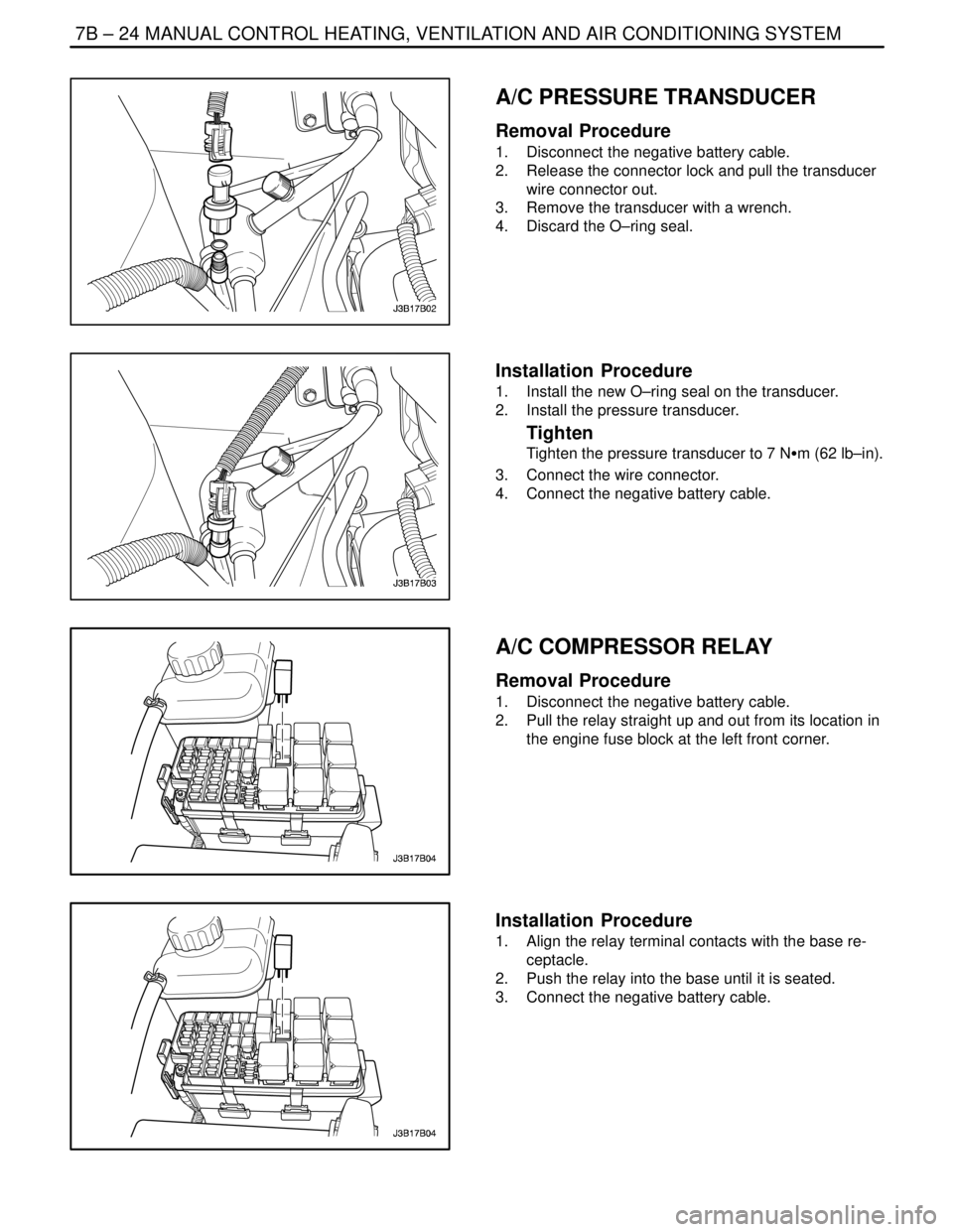
A/C PRESSURE TRANSDUCER
Removal Procedure
1. Disconnect the negative battery cable.
2. Release the connector lock and pull the transducer
wire connector out.
3. Remove the transducer with a wrench.
4. Discard the O–ring seal.
Installation Procedure
1. Install the new O–ring seal on the transducer.
2. Install the pressure transducer.
Tighten
Tighten the pressure transducer to 7 NSm (62 lb–in).
3. Connect the wire connector.
4. Connect the negative battery cable.
A/C COMPRESSOR RELAY
Removal Procedure
1. Disconnect the negative battery cable.
2. Pull the relay straight up and out from its location in
the engine fuse block at the left front corner.
Installation Procedure
1. Align the relay terminal contacts with the base re-
ceptacle.
2. Push the relay into the base until it is seated.
3. Connect the negative battery cable.
Page 2027 of 2643
MANUAL CONTROL HEATING, VENTILATION AND AIR CONDITIONING SYSTEM 7B – 25
DAEWOO V–121 BL4
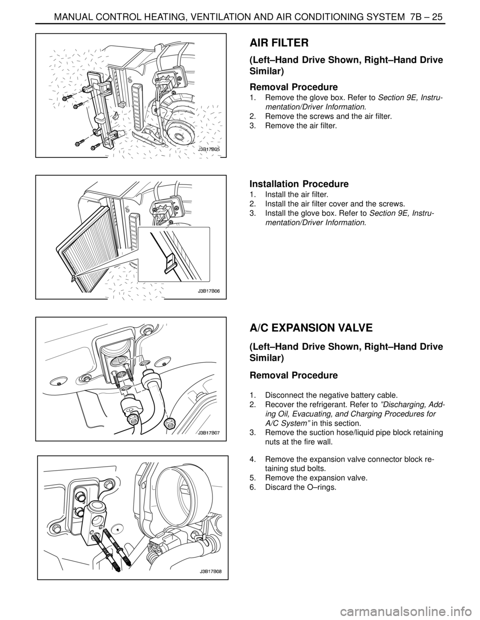
AIR FILTER
(Left–Hand Drive Shown, Right–Hand Drive
Similar)
Removal Procedure
1. Remove the glove box. Refer to Section 9E, Instru-
mentation/Driver Information.
2. Remove the screws and the air filter.
3. Remove the air filter.
Installation Procedure
1. Install the air filter.
2. Install the air filter cover and the screws.
3. Install the glove box. Refer to Section 9E, Instru-
mentation/Driver Information.
A/C EXPANSION VALVE
(Left–Hand Drive Shown, Right–Hand Drive
Similar)
Removal Procedure
1. Disconnect the negative battery cable.
2. Recover the refrigerant. Refer to ”Discharging, Add-
ing Oil, Evacuating, and Charging Procedures for
A/C System” in this section.
3. Remove the suction hose/liquid pipe block retaining
nuts at the fire wall.
4. Remove the expansion valve connector block re-
taining stud bolts.
5. Remove the expansion valve.
6. Discard the O–rings.
Page 2028 of 2643
7B – 26IMANUAL CONTROL HEATING, VENTILATION AND AIR CONDITIONING SYSTEM
DAEWOO V–121 BL4
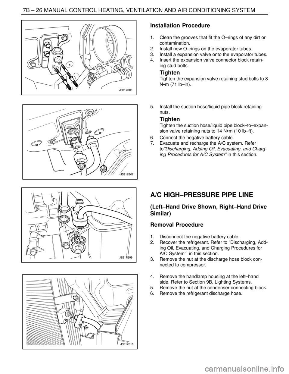
Installation Procedure
1. Clean the grooves that fit the O–rings of any dirt or
contamination.
2. Install new O–rings on the evaporator tubes.
3. Install a expansion valve onto the evaporator tubes.
4. Insert the expansion valve connector block retain-
ing stud bolts.
Tighten
Tighten the expansion valve retaining stud bolts to 8
NSm (71 lb–in).
5. Install the suction hose/liquid pipe block retaining
nuts.
Tighten
Tighten the suction hose/liquid pipe block–to–expan-
sion valve retaining nuts to 14 NSm (10 lb–ft).
6. Connect the negative battery cable.
7. Evacuate and recharge the A/C system. Refer
to”Discharging, Adding Oil, Evacuating, and Charg-
ing Procedures for A/C System” in this section.
A/C HIGH–PRESSURE PIPE LINE
(Left–Hand Drive Shown, Right–Hand Drive
Similar)
Removal Procedure
1. Disconnect the negative battery cable.
2. Recover the refrigerant. Refer to ”Discharging, Add-
ing Oil, Evacuating, and Charging Procedures for
A/C System” in this section.
3. Remove the nut at the discharge hose block con-
nected to compressor.
4. Remove the handlamp housing at the left–hand
side. Refer to Section 9B, Lighting Systems.
5. Remove the nut at the condenser connecting block.
6. Remove the refrigerant discharge hose.
Page 2030 of 2643
7B – 28IMANUAL CONTROL HEATING, VENTILATION AND AIR CONDITIONING SYSTEM
DAEWOO V–121 BL4
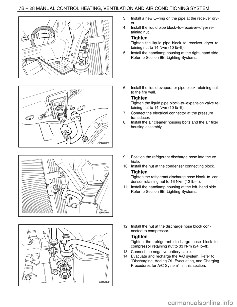
3. Install a new O–ring on the pipe at the receiver dry-
er.
4. Install the liquid pipe block–to–receiver–dryer re-
taining nut.
Tighten
Tighten the liquid pipe block–to–receiver–dryer re-
taining nut to 14 NSm (10 lb–ft).
5. Install the handlamp housing at the right–hand side.
Refer to Section 9B, Lighting Systems.
6. Install the liquid evaporator pipe block retaining nut
to the fire wall.
Tighten
Tighten the liquid pipe block–to–expansion valve re-
taining nut to 14 NSm (10 lb–ft).
7. Connect the electrical connector at the pressure
transducer.
8. Install the air cleaner housing bolts and the air filter
housing assembly.
9. Position the refrigerant discharge hose into the ve-
hicle.
10. Install the nut at the condenser connecting block.
Tighten
Tighten the refrigerant discharge hose block–to–con-
denser retaining nut to 16 NSm (12 lb–ft).
11. Install the handlamp housing at the left–hand side.
Refer to Section 9B, Lighting Systems.
12. Install the nut at the discharge hose block con-
nected to compressor.
Tighten
Tighten the refrigerant discharge hose block–to–
compressor retaining nut to 33 NSm (24 lb–ft).
13. Connect the negative battery cable.
14. Evacuate and recharge the A/C system. Refer to
”Discharging, Adding Oil, Evacuating, and Charging
Procedures for A/C System” in this section.
Page 2031 of 2643
MANUAL CONTROL HEATING, VENTILATION AND AIR CONDITIONING SYSTEM 7B – 29
DAEWOO V–121 BL4
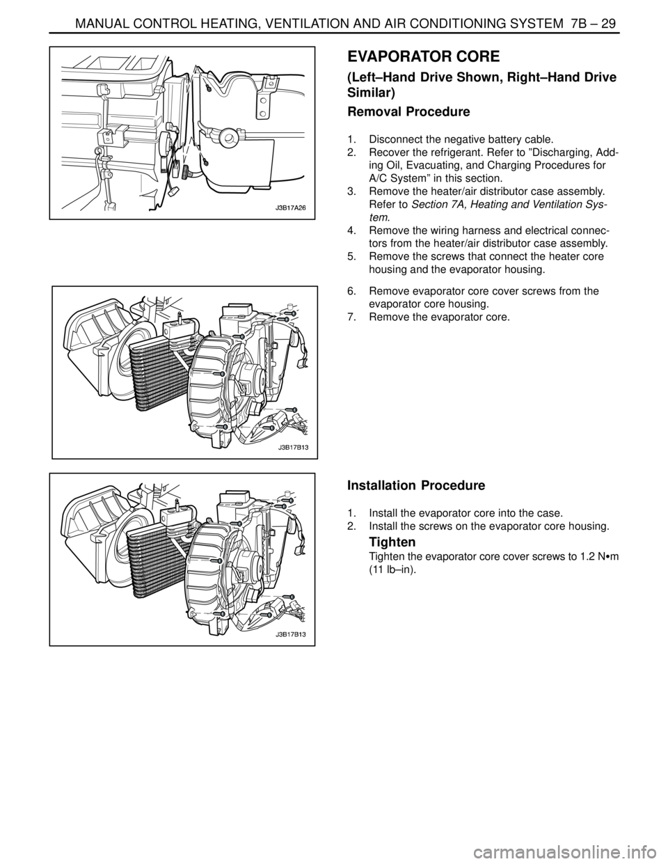
EVAPORATOR CORE
(Left–Hand Drive Shown, Right–Hand Drive
Similar)
Removal Procedure
1. Disconnect the negative battery cable.
2. Recover the refrigerant. Refer to ”Discharging, Add-
ing Oil, Evacuating, and Charging Procedures for
A/C System” in this section.
3. Remove the heater/air distributor case assembly.
Refer to Section 7A, Heating and Ventilation Sys-
tem.
4. Remove the wiring harness and electrical connec-
tors from the heater/air distributor case assembly.
5. Remove the screws that connect the heater core
housing and the evaporator housing.
6. Remove evaporator core cover screws from the
evaporator core housing.
7. Remove the evaporator core.
Installation Procedure
1. Install the evaporator core into the case.
2. Install the screws on the evaporator core housing.
Tighten
Tighten the evaporator core cover screws to 1.2 NSm
(11 lb–in).