2004 DAEWOO NUBIRA battery
[x] Cancel search: batteryPage 2044 of 2643
7B – 42IMANUAL CONTROL HEATING, VENTILATION AND AIR CONDITIONING SYSTEM
DAEWOO V–121 BL4
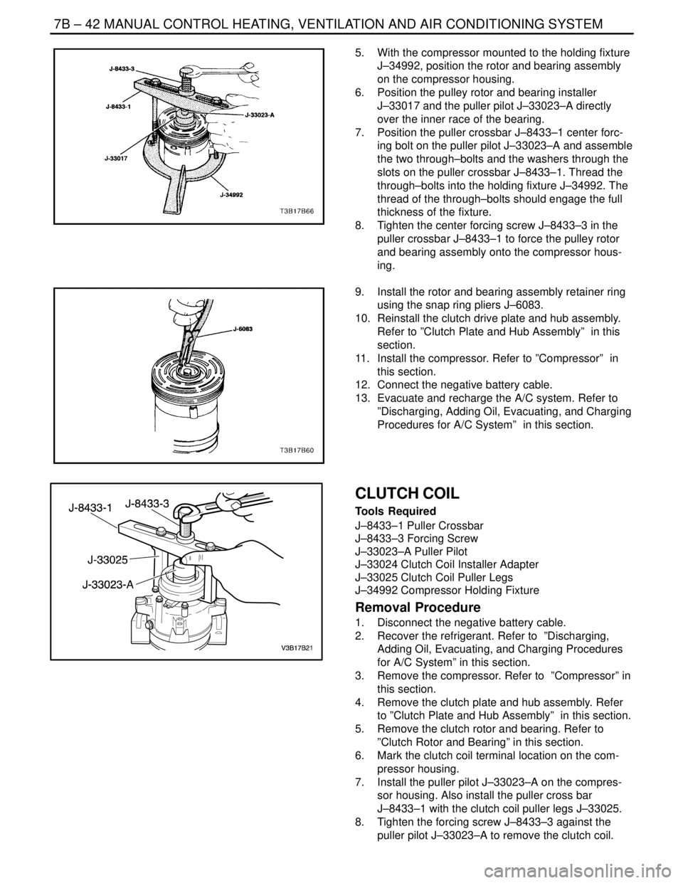
5. With the compressor mounted to the holding fixture
J–34992, position the rotor and bearing assembly
on the compressor housing.
6. Position the pulley rotor and bearing installer
J–33017 and the puller pilot J–33023–A directly
over the inner race of the bearing.
7. Position the puller crossbar J–8433–1 center forc-
ing bolt on the puller pilot J–33023–A and assemble
the two through–bolts and the washers through the
slots on the puller crossbar J–8433–1. Thread the
through–bolts into the holding fixture J–34992. The
thread of the through–bolts should engage the full
thickness of the fixture.
8. Tighten the center forcing screw J–8433–3 in the
puller crossbar J–8433–1 to force the pulley rotor
and bearing assembly onto the compressor hous-
ing.
9. Install the rotor and bearing assembly retainer ring
using the snap ring pliers J–6083.
10. Reinstall the clutch drive plate and hub assembly.
Refer to ”Clutch Plate and Hub Assembly” in this
section.
11. Install the compressor. Refer to ”Compressor” in
this section.
12. Connect the negative battery cable.
13. Evacuate and recharge the A/C system. Refer to
”Discharging, Adding Oil, Evacuating, and Charging
Procedures for A/C System” in this section.
CLUTCH COIL
Tools Required
J–8433–1 Puller Crossbar
J–8433–3 Forcing Screw
J–33023–A Puller Pilot
J–33024 Clutch Coil Installer Adapter
J–33025 Clutch Coil Puller Legs
J–34992 Compressor Holding Fixture
Removal Procedure
1. Disconnect the negative battery cable.
2. Recover the refrigerant. Refer to ”Discharging,
Adding Oil, Evacuating, and Charging Procedures
for A/C System” in this section.
3. Remove the compressor. Refer to ”Compressor” in
this section.
4. Remove the clutch plate and hub assembly. Refer
to ”Clutch Plate and Hub Assembly” in this section.
5. Remove the clutch rotor and bearing. Refer to
”Clutch Rotor and Bearing” in this section.
6. Mark the clutch coil terminal location on the com-
pressor housing.
7. Install the puller pilot J–33023–A on the compres-
sor housing. Also install the puller cross bar
J–8433–1 with the clutch coil puller legs J–33025.
8. Tighten the forcing screw J–8433–3 against the
puller pilot J–33023–A to remove the clutch coil.
Page 2045 of 2643
MANUAL CONTROL HEATING, VENTILATION AND AIR CONDITIONING SYSTEM 7B – 43
DAEWOO V–121 BL4
Installation Procedure
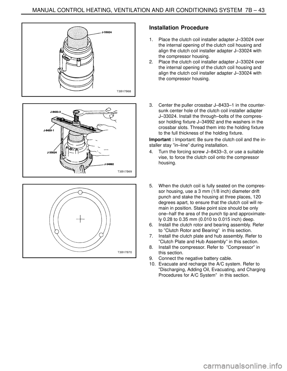
1. Place the clutch coil installer adapter J–33024 over
the internal opening of the clutch coil housing and
align the clutch coil installer adapter J–33024 with
the compressor housing.
2. Place the clutch coil installer adapter J–33024 over
the internal opening of the clutch coil housing and
align the clutch coil installer adapter J–33024 with
the compressor housing.
3. Center the puller crossbar J–8433–1 in the counter-
sunk center hole of the clutch coil installer adapter
J–33024. Install the through–bolts of the compres-
sor holding fixture J–34992 and the washers in the
crossbar slots. Thread them into the holding fixture
to the full thickness of the holding fixture.
Important : Important: Be sure the clutch coil and the in-
staller stay ”in–line” during installation.
4. Turn the forcing screw J–8433–3, or use a suitable
vise, to force the clutch coil onto the compressor
housing.
5. When the clutch coil is fully seated on the compres-
sor housing, use a 3 mm (1/8 inch) diameter drift
punch and stake the housing at three places, 120
degrees apart, to ensure that the clutch coil will re-
main in position. Stake point size should be only
one–half the area of the punch tip and approximate-
ly 0.28 to 0.35 mm (0.010 to 0.015 inch) deep.
6. Install the clutch rotor and bearing assembly. Refer
to ”Clutch Rotor and Bearing” in this section.
7. Install the clutch plate and hub assembly. Refer to
”Clutch Plate and Hub Assembly” in this section.
8. Install the compressor. Refer to ”Compressor” in
this section.
9. Connect the negative battery cable.
10. Evacuate and recharge the A/C system. Refer to
”Discharging, Adding Oil, Evacuating, and Charging
Procedures for A/C System” in this section.
Page 2046 of 2643
7B – 44IMANUAL CONTROL HEATING, VENTILATION AND AIR CONDITIONING SYSTEM
DAEWOO V–121 BL4
SHAFT SEAL REPLACEMENT
Tools Required
J–5403 Snap Ring Pliers
J–9553–1 O–Ring Remover
J–23128–A Seal Seat Remover/Installer
J–33011 O–Ring Installer
J–34614 Shaft Seal Protector
Important : A shaft seal should not be replaced because
a small amount of oil is found on the adjacent surface. The
seal is designed to leak some oil for lubrication purposes.
A shaft seal should be changed only when a large amount
of sprayed oil is found and then only after actual refrigerant
leakage is found by using an approved leak detection pro-
cedure. Refer to ”Leak Testing the Refrigerant System” in
this section.
Should a compressor shaft seal ever have to be replaced,
the receiver–dryer in this system must also be removed
from the vehicle. The oil in the receiver–dryer must then
be drained, measured and replaced. Refer to ”Discharg-
ing, Adding Oil, Evacuating, and Charging Procedures for
A/C System” in this section.
Removal Procedure
1. Disconnect the negative battery cable.
2. Recover the refrigerant. Refer to ”Discharging, Add-
ing Oil, Evacuating, and Charging Procedures for
A/C System” in this section.
3. Loosen and reposition the compressor in the
mounting brackets.
4. Remove the clutch drive plate and hub assembly
from the compressor. Refer to ”Clutch Plate and
Hub Assembly” in this section.
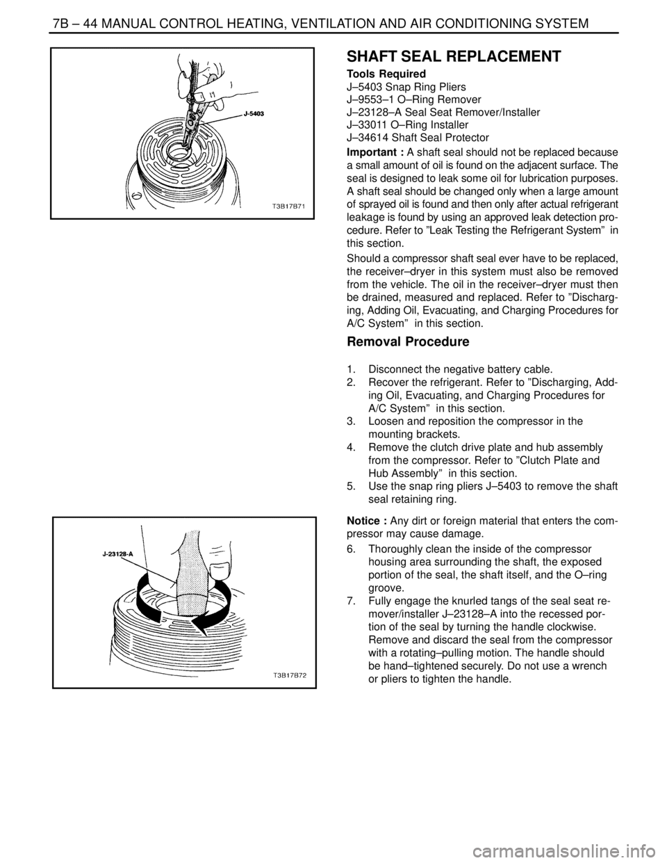
5. Use the snap ring pliers J–5403 to remove the shaft
seal retaining ring.
Notice : Any dirt or foreign material that enters the com-
pressor may cause damage.
6. Thoroughly clean the inside of the compressor
housing area surrounding the shaft, the exposed
portion of the seal, the shaft itself, and the O–ring
groove.
7. Fully engage the knurled tangs of the seal seat re-
mover/installer J–23128–A into the recessed por-
tion of the seal by turning the handle clockwise.
Remove and discard the seal from the compressor
with a rotating–pulling motion. The handle should
be hand–tightened securely. Do not use a wrench
or pliers to tighten the handle.
Page 2048 of 2643
7B – 46IMANUAL CONTROL HEATING, VENTILATION AND AIR CONDITIONING SYSTEM
DAEWOO V–121 BL4
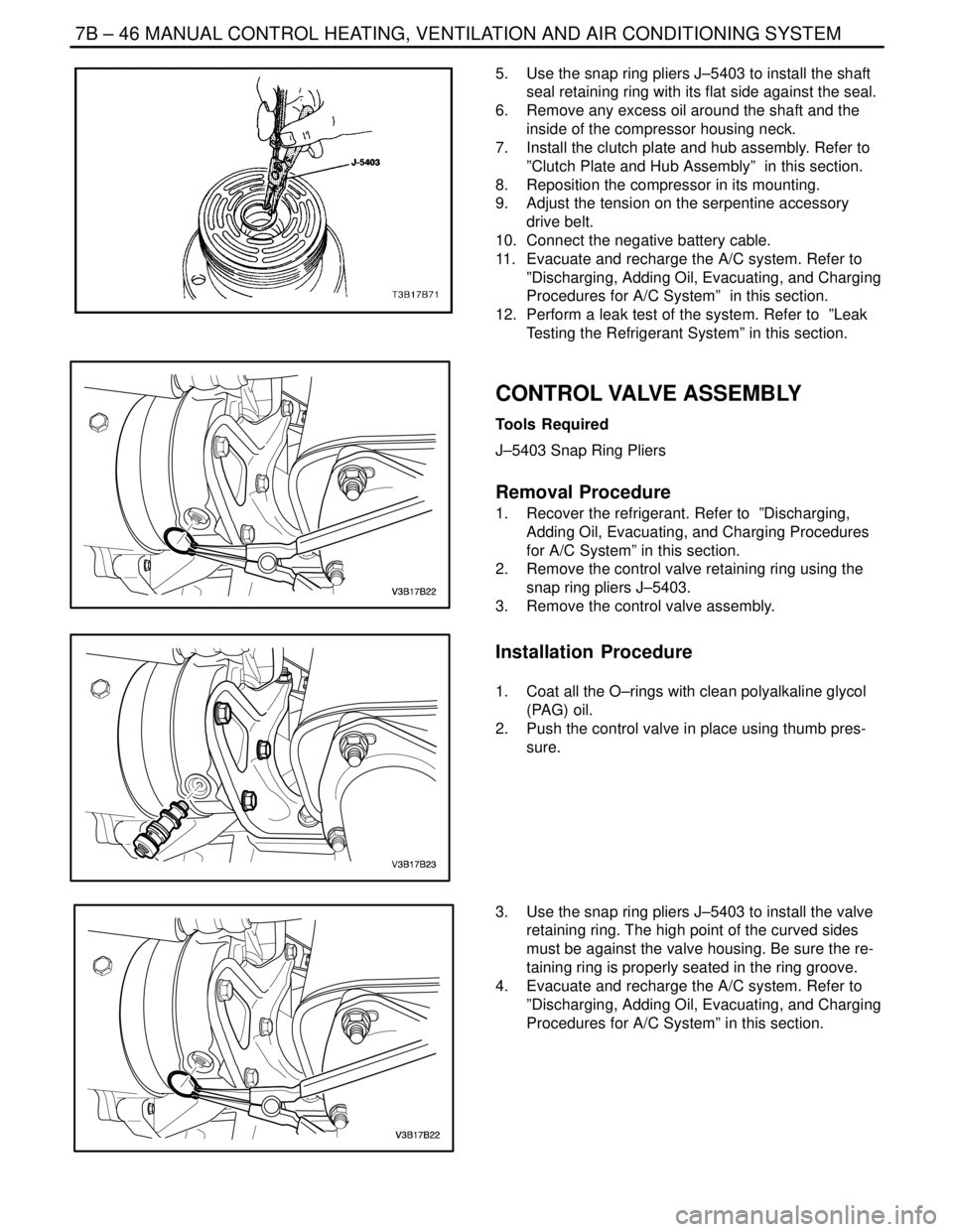
5. Use the snap ring pliers J–5403 to install the shaft
seal retaining ring with its flat side against the seal.
6. Remove any excess oil around the shaft and the
inside of the compressor housing neck.
7. Install the clutch plate and hub assembly. Refer to
”Clutch Plate and Hub Assembly” in this section.
8. Reposition the compressor in its mounting.
9. Adjust the tension on the serpentine accessory
drive belt.
10. Connect the negative battery cable.
11. Evacuate and recharge the A/C system. Refer to
”Discharging, Adding Oil, Evacuating, and Charging
Procedures for A/C System” in this section.
12. Perform a leak test of the system. Refer to ”Leak
Testing the Refrigerant System” in this section.
CONTROL VALVE ASSEMBLY
Tools Required
J–5403 Snap Ring Pliers
Removal Procedure
1. Recover the refrigerant. Refer to ”Discharging,
Adding Oil, Evacuating, and Charging Procedures
for A/C System” in this section.
2. Remove the control valve retaining ring using the
snap ring pliers J–5403.
3. Remove the control valve assembly.
Installation Procedure
1. Coat all the O–rings with clean polyalkaline glycol
(PAG) oil.
2. Push the control valve in place using thumb pres-
sure.
3. Use the snap ring pliers J–5403 to install the valve
retaining ring. The high point of the curved sides
must be against the valve housing. Be sure the re-
taining ring is properly seated in the ring groove.
4. Evacuate and recharge the A/C system. Refer to
”Discharging, Adding Oil, Evacuating, and Charging
Procedures for A/C System” in this section.
Page 2056 of 2643

SECTION : 7D
AUTOMATIC TEMPERATURE CONTROL
HEATING, VENTILATION, AND AIR
CONDITIONING SYSTEM
CAUTION : Disconnect the negative battery cable before removing or installing any electrical unit or when a tool
or equipment could easily come in contact with exposed electrical terminals. Disconnecting this cable will help
prevent personal injury and damage to the vehicle. The ignition must also be in LOCK unless otherwise noted.
TABLE OF CONTENTS
SPECIFICATIONS7D–2 . . . . . . . . . . . . . . . . . . . . . . . . . .
Fastener Tightening Specifications 7D–2. . . . . . . . . . .
SCHEMATIC AND ROUTING DIAGRAMS7D–3 . . . . .
A/C Sensors/Defoggers and A/C Compressor
Controls Diagram 7D–3. . . . . . . . . . . . . . . . . . . . . . . .
A/C Blower and Motor Controls Diagram 7D–4. . . . . .
DIAGNOSIS7D–5 . . . . . . . . . . . . . . . . . . . . . . . . . . . . . . . .
GENERAL A/C DIAGNOSTICS 7D–5. . . . . . . . . . . . . . .
V5 SYSTEM AIR CONDITIONING AND AUTOMATIC
TEMPERATURE CONTROL (ATC) 7D–5. . . . . . . . . .
Self–Diagnostic Circuit Check 7D–5. . . . . . . . . . . . . . .
Automatic Temperature Controller Does Not
Operate When Ignition Is ON 7D–6. . . . . . . . . . . . . .
Controller Does Not Illuminate When Light Switch
Is ON 7D–7. . . . . . . . . . . . . . . . . . . . . . . . . . . . . . . . . .
No Hot Air From Blower 7D–8. . . . . . . . . . . . . . . . . . . .
No Cool Air From Blower 7D–10. . . . . . . . . . . . . . . . . .
Blower Motor Does Not Run At All 7D–12. . . . . . . . . .
Mode Control Do Not Work 7D–14. . . . . . . . . . . . . . . .
Air Source Selection Not Controlled 7D–16. . . . . . . . .
Compressor Magnetic Clutch Does Not
Engage 7D–17. . . . . . . . . . . . . . . . . . . . . . . . . . . . . . . .
DIAGNOSTIC TROUBLE CODES 7D–18. . . . . . . . . . . .
Code 1 – In–Car Sensor Error 7D–18. . . . . . . . . . . . .
Code 2 – Ambient Air Temperature Sensor
Error 7D–20. . . . . . . . . . . . . . . . . . . . . . . . . . . . . . . . . .
Code 3 – Water Sensor Error 7D–22. . . . . . . . . . . . . . .
Code 4 – Air Mix Door Error 7D–24. . . . . . . . . . . . . . . . Code 5 – Sun Sensor Error 7D–27. . . . . . . . . . . . . . . .
Code 6 – Power Transistor Error 7D–29. . . . . . . . . . . .
Code 7 – Max–Hi Relay Error 7D–31. . . . . . . . . . . . . .
MAINTENANCE AND REPAIR7D–32 . . . . . . . . . . . . . .
ON–VEHICLE SERVICE 7D–32. . . . . . . . . . . . . . . . . . . .
GENERAL A/C SYSTEM SERVICE
PROCEURES 7D–32. . . . . . . . . . . . . . . . . . . . . . . . . . . .
General Service Procedures 7D–32. . . . . . . . . . . . . . .
SERVICEABLE COMPONENTS 7D–33. . . . . . . . . . . . .
Common HVAC Components 7D–33. . . . . . . . . . . . . . .
Automatic Temperature Control Assembly 7D–33. . . .
Inlet Air Door Motor 7D–34. . . . . . . . . . . . . . . . . . . . . . .
Mode Door Motor 7D–35. . . . . . . . . . . . . . . . . . . . . . . . .
Air Mix Door Motor 7D–35. . . . . . . . . . . . . . . . . . . . . . . .
Water Sensor 7D–36. . . . . . . . . . . . . . . . . . . . . . . . . . . .
Ambient Air Temperature Sensor 7D–36. . . . . . . . . . .
In–Car Temperature Sensor 7D–37. . . . . . . . . . . . . . . .
Sun Sensor 7D–37. . . . . . . . . . . . . . . . . . . . . . . . . . . . . .
UNIT REPAIR 7D–39. . . . . . . . . . . . . . . . . . . . . . . . . . . . .
V5 AIR CONDITIONING COMPRESSOR
OVERHAUL 7D–39. . . . . . . . . . . . . . . . . . . . . . . . . . . . .
Compressor Overhaul 7D–39. . . . . . . . . . . . . . . . . . . . .
GENERAL DESCRIPTION AND SYSTEM
OPERATION7D–40 . . . . . . . . . . . . . . . . . . . . . . . . . . . . .
GENERAL INFORMATION 7D–40. . . . . . . . . . . . . . . . . .
The V5 System 7D–40. . . . . . . . . . . . . . . . . . . . . . . . . . .
System Components – Control 7D–40. . . . . . . . . . . . .
Page 2088 of 2643
IAUTOMATIC TEMPERATURE CONTROL HEATING, VENTILATION, AND AIR CONDITIONING SYSTEM 7D – 33
DAEWOO V–121 BL4
SERVICEABLE COMPONENTS
COMMON HVAC COMPONENTS
Those components used in non–automatic systems are
covered in other sections of this manual.
Refer to Section 7A, Heating and Ventilation System for
the following procedures:
S Blower Motor.
S Heater Hoses.
S Blower Resistor.
S High–Blower Relay.
S Heater/Air Distributor Case Assembly (A/C Mod-
ule).
S Heater Core.
Refer to Section 7B, Manual Control Heating, Ventilation,
and Air Conditioning System, for the following proce-
dures:
S A/C Pressure Transducer.
S A/C Compressor Relay.
S Air Filter.
S A/C Expansion Valve.
S A/C High–Pressure Pipe Line.
S Evaporator Core.
S A/C Suction Hose Assembly.
S A/C Discharge Hose–Compressor to Condenser.
S Compressor.
S Condenser.
S Receiver–Dryer.
AUTOMATIC TEMPERATURE
CONTROL ASSEMBLY
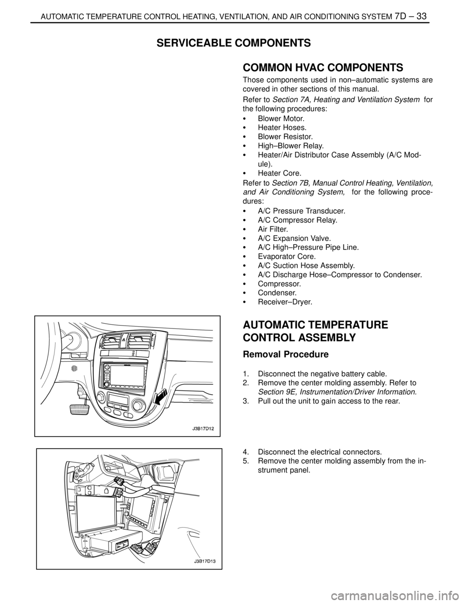
Removal Procedure
1. Disconnect the negative battery cable.
2. Remove the center molding assembly. Refer to
Section 9E, Instrumentation/Driver Information.
3. Pull out the unit to gain access to the rear.
4. Disconnect the electrical connectors.
5. Remove the center molding assembly from the in-
strument panel.
Page 2089 of 2643
7D – 34IAUTOMATIC TEMPERATURE CONTROL HEATING, VENTILATION, AND AIR CONDITIONING SYSTEM
DAEWOO V–121 BL4
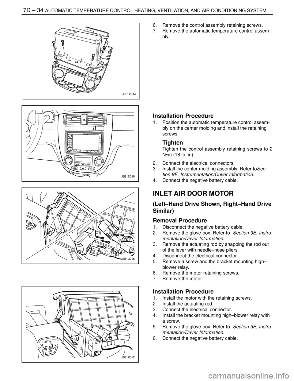
6. Remove the control assembly retaining screws.
7. Remove the automatic temperature control assem-
bly.
Installation Procedure
1. Position the automatic temperature control assem-
bly on the center molding and install the retaining
screws.
Tighten
Tighten the control assembly retaining screws to 2
NSm (18 lb–in).
2. Connect the electrical connectors.
3. Install the center molding assembly. Refer toSec-
tion 9E, Instrumentation/Driver Information.
4. Connect the negative battery cable.
INLET AIR DOOR MOTOR
(Left–Hand Drive Shown, Right–Hand Drive
Similar)
Removal Procedure
1. Disconnect the negative battery cable.
2. Remove the glove box. Refer to Section 9E, Instru-
mentation/Driver Information.
3. Remove the actuating rod by snapping the rod out
of the lever with needle–nose pliers.
4. Disconnect the electrical connector.
5. Remove a screw and the bracket mounting high–
blower relay.
6. Remove the motor retaining screws.
7. Remove the motor.
Installation Procedure
1. Install the motor with the retaining screws.
2. Install the actuating rod.
3. Connect the electrical connector.
4. Install the bracket mounting high–blower relay with
a screw.
5. Remove the glove box. Refer to Section 9E, Instru-
mentation/Driver Information.
6. Connect the negative battery cable.
Page 2090 of 2643
IAUTOMATIC TEMPERATURE CONTROL HEATING, VENTILATION, AND AIR CONDITIONING SYSTEM 7D – 35
DAEWOO V–121 BL4
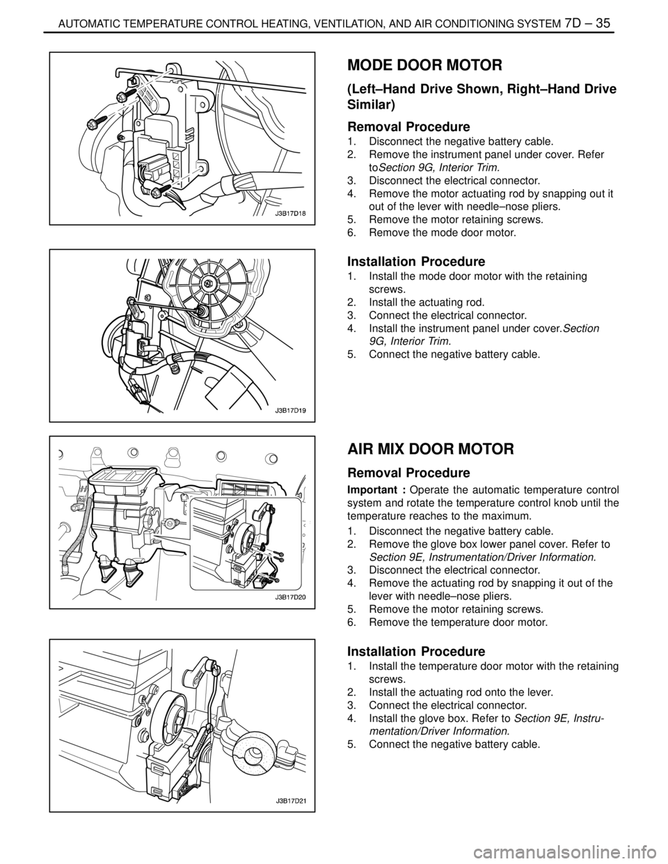
MODE DOOR MOTOR
(Left–Hand Drive Shown, Right–Hand Drive
Similar)
Removal Procedure
1. Disconnect the negative battery cable.
2. Remove the instrument panel under cover. Refer
toSection 9G, Interior Trim.
3. Disconnect the electrical connector.
4. Remove the motor actuating rod by snapping out it
out of the lever with needle–nose pliers.
5. Remove the motor retaining screws.
6. Remove the mode door motor.
Installation Procedure
1. Install the mode door motor with the retaining
screws.
2. Install the actuating rod.
3. Connect the electrical connector.
4. Install the instrument panel under cover.Section
9G, Interior Trim.
5. Connect the negative battery cable.
AIR MIX DOOR MOTOR
Removal Procedure
Important : Operate the automatic temperature control
system and rotate the temperature control knob until the
temperature reaches to the maximum.
1. Disconnect the negative battery cable.
2. Remove the glove box lower panel cover. Refer to
Section 9E, Instrumentation/Driver Information.
3. Disconnect the electrical connector.
4. Remove the actuating rod by snapping it out of the
lever with needle–nose pliers.
5. Remove the motor retaining screws.
6. Remove the temperature door motor.
Installation Procedure
1. Install the temperature door motor with the retaining
screws.
2. Install the actuating rod onto the lever.
3. Connect the electrical connector.
4. Install the glove box. Refer to Section 9E, Instru-
mentation/Driver Information.
5. Connect the negative battery cable.