2004 DAEWOO NUBIRA gear shift
[x] Cancel search: gear shiftPage 20 of 2643

GENERAL INFORMATION 0B – 13
DAEWOO V–121 BL4
EACH TIME THE OIL IS CHANGED
Automatic Transaxle Fluid
Refer to fluid level service procedure of Section 5A, ZF
4HP16 Automatic Transaxle.
Manual Transaxle
Check the fluid level and add fluid as required. Refer to
Section 5B, Five–Speed Manual Transaxle.
Brake System Inspection
This inspection should be done when the wheels are re-
moved for rotation. Inspect the lines and the hoses for
proper hookup, binding, leaks, cracks, chafing, etc. In-
spect the disc brake pads for wear. Inspect the rotors for
surface condition. Also inspect the drum brake linings for
wear and cracks. Inspect other brake parts, including the
drums, the wheels cylinders, the parking brake, etc., at the
same time. Check the parking brake adjustment. Inspect
the brakes more often if habit or conditions result in fre-
quent braking.
Steering, Suspension and Front Drive Axle
Boot And Seal Inspection
Inspect the front and rear suspension and the steering
system for damaged, loose or missing parts, signs of wear
or lack of lubrication. Inspect the power steering lines and
the hoses for proper hookup, binding, leaks, cracks, chaf-
ing, etc. Clean and inspect the drive axle boot and seals
for damage, tears or leakage. Replace the seals if neces-
sary.
Exhaust System Inspection
Inspect the complete system (including the catalytic con-
verter if equipped). Inspect the body near the exhaust sys-
tem. Look for broken, damaged, missing, or out–of–posi-
tion parts as well as open seams, holes, loose
connections, or other conditions which could cause heat
buildup in the floor pan or could let exhaust fumes seep
into the trunk or passenger compartment.
Throttle Linkage Inspection
Inspect the throttle linkage for interference or binding,
damaged, or missing parts. Lubricate all linkage joints and
throttle cable joints, the intermediate throttle shaft bearing,
the return spring at throttle valve assembly, and the accel-
erator pedal sliding face with suitable grease. Check the
throttle cable for free movements.
Engine Drive Belts
Inspect all belts for cracks, fraying, wear and proper ten-
sion. Adjust or replace the belts as needed.
Hood Latch Operation
When opening the hood, note the operation of the secon-
dary latch. It should keep the hood from opening all the
way when the primary latch is released. The hood must
close firmly.
AT LEAST ANNUALLY
Lap and Shoulder Belts Condition and
Operation
Inspect the belt system including: the webbing, the
buckles, the latch plates, the retractor, the guide loops and
the anchors.
Movable Head Restraint Operation
On vehicles with movable head restraints, the restraints
must stay in the desired position.
Spare Tire and Jack Storage
Be alert to rattles in the rear of the vehicle. The spare tire,
all the jacking equipment, and the tools must be securely
stowed at all times. Oil the jack ratchet or the screw mech-
anism after each use.
Key Lock Service
Lubricate the key lock cylinder.
Body Lubrication Service
Lubricate all the body door hinges including the hood, the
fuel door, the rear compartment hinges and the latches,
the glove box and the console doors, and any folding seat
hardware.
Transaxle Neutral Switch Operation on
Automatic Transaxle
CAUTION : Take the following precautions because
the vehicle could move without warning and possibly
cause personal injury or property damage:
S Firmly apply the parking brake and the regular
brakes.
S Do not use the accelerator pedal.
S Be ready to promptly turn off the ignition if the ve-
hicle starts.
On automatic transaxle vehicles, try to start the engine in
each gear. The starter should crank only in P (Park) or N
(Neutral).
Parking Brake and Transaxle P (Park)
Mechanism Operation
CAUTION : In order to reduce the risk of personal in-
jury or property damage, be prepared to apply the reg-
ular brakes promptly if the vehicle begins to move.
Park on a fairly steep hill with enough room for movement
in the downhill direction. To check the parking brake, with
the engine running and the transaxle in N (Neutral), slowly
remove foot pressure from the regular brake pedal (until
only the parking brake is holding the vehicle).
To check the automatic transaxle P (Park) mechanism’s
holding ability, release all brakes after shifting the trans-
axle to P (Park).
Underbody Flushing
Flushing the underbody will remove any corrosive materi-
als used for ice and snow removal and dust control. At
least every spring clean the underbody. First, loosen the
sediment packed in closed areas of the vehicle. Then flush
the underbody with plain water.
Page 246 of 2643

1E – 32IENGINE ELECTRICAL
DAEWOO V–121 BL4
the same cable to the positive terminal on the other
battery. Never connect the other end to the nega-
tive terminal of the discharged battery.
CAUTION : To avoid injury do not attach the cable di-
rectly to the negative terminal of the discharged bat-
tery. Doing so could cause sparks and a possible bat-
tery explosion.
6. Clamp one end of the second cable to the negative
terminal of the booster battery. Make the final con-
nection to a solid engine ground (such as the en-
gine lift bracket) at least 450 millimeters (18 inches)
from the discharged battery.
7. Start the engine of the vehicle with the good bat-
tery. Run the engine at a moderate speed for sever-
al minutes. Then start the engine of the vehicle
which has the discharged battery.
8. Remove the jumper cables by reversing the above
sequence exactly. Remove the negative cable from
the vehicle with the discharged battery first. While
removing each clamp, take care that it does not
touch any other metal while the other end remains
attached.
GENERATOR
The Delco–Remy CS charging system has several mod-
els available, including the CS. The number denotes the
outer diameter in millimeters of the stator lamination.
CS generators are equipped with internal regulators. A
Delta stator, a rectifier bridge, and a rotor with slip rings
and brushes are electrically similar to earlier generators.
A conventional pulley and fan are used. There is no test
hole.
Unlike three–wire generators, the CS may be used with
only two connections: battery positive and an ”L’’ terminal
to the charge indicator lamp.
As with other charging systems, the charge indicator lamp
lights when the ignition switch is turned to RUN, and goes
out when the engine is running. If the charge indicator is
on with the engine running, a charging system defect is in-
dicated. This indicator light will glow at full brilliance for
several kinds of defects as well as when the system volt-
age is too high or too low.The regulator voltage setting varies with temperature and
limits the system voltage by controlling rotor field current.
At high speeds, the on–time may be 10 percent and the
off–time 90 percent. At low speeds, with high electrical
loads, on–time may be 90 percent and the off–time 10 per-
cent.
CHARGING SYSTEM
CS generators use a new type of regulator that incorpo-
rates a diode trio. A Delta stator, a rectifier bridge, and a
rotor with slip rings and brushes are electrically similar to
earlier generators. A conventional pulley and fan are used.
There is no test hole.
STARTER
Wound field starter motors have pole pieces, arranged
around the armature, which are energized by wound field
coils.
Enclosed shift lever cranking motors have the shift lever
mechanism and the solenoid plunger enclosed in the drive
housing, protecting them from exposure to dirt, icy condi-
tions, and splashes.
In the basic circuit, solenoid windings are energized when
the switch is closed. The resulting plunger and shift lever
movement causes the pinion to engage the engine fly-
wheel ring gear. The solenoid main contacts close. Crank-
ing then takes place.
When the engine starts, pinion overrun protects the arma-
ture from excessive speed until the switch is opened, at
which time the return spring causes the pinion to disen-
gage. To prevent excessive overrun, the switch should be
released immediately after the engine starts.
STARTING SYSTEM
The engine electrical system includes the battery, the igni-
tion, the starter, the generator, and all the related wiring.
Diagnostic tables will aid in troubleshooting system faults.
When a fault is traced to a particular component, refer to
that component section of the service manual.
The starting system circuit consists of the battery, the
starter motor, the ignition switch, and all the related electri-
cal wiring. All of these components are connected electri-
cally.
Page 833 of 2643

ENGINE CONTROLS 1F – 587
DAEWOO V–121 BL4
POOR FUEL ECONOMY
Definition : Fuel economy, as measured by an actual road
test, is noticeably lower than expected. Also, fuel econo-
my is noticeably lower than it was on this vehicle at one
time, as previously shown by an actual road test.
Important : Driving habits affect fuel economy. Check the
owner’s driving habits by asking the following questions:1. Is the A/C system (i.e. defroster mode) turned on
all the time?
2. Are the tires at the correct air pressure?
3. Have excessively heavy loads been carried?
4. Does the driver accelerate too much and too often?
Suggest the driver read the section in the owner’s
manual about fuel economy.
Step
ActionValue(s)YesNo
1Were the Important Preliminary Checks performed?–Go toStep 2Go to
”Important Pre-
liminary
Checks”
21. Inspect the air filter for excessive contamina-
tion.
2. Inspect for fuel system leaks.
Are all needed checks complete?–Go toStep 3–
31. Inspect the spark plugs for excessive wear,
insulation cracks, improper gap, or heavy de-
posits.
2. Replace any faulty spark plugs.
3. Inspect the ignition wires for cracking, hard-
ness, and proper connections.
Are all needed checks and repairs complete?–Go toStep 4–
41. Inspect the engine coolant level.
2. Check the thermostat for being always open or
for an incorrect heat range.
3. Replace the thermostat as needed.
Are all needed checks and repairs complete?–Go toStep 5–
51. Check the transaxle shift pattern. Ensure all
transaxle gears are functioning.
2. Check the Torque Converter Clutch (TCC) op-
eration with a scan tool. The scan tool should
indicate rpm drop when the TCC is command-
ed on.
3. Check for proper calibration of the speedome-
ter.
4. Check the brakes for dragging.
5. Check the cylinder compression.
6. Repair, replace, or adjust any components as
needed.
Are all checks and needed repairs complete?–System OK–
Page 1154 of 2643
4G – 2IPARKING BRAKE
DAEWOO V–121 BL4
MAINTENANCE AND REPAIR
ON–VEHICLE SERVICE
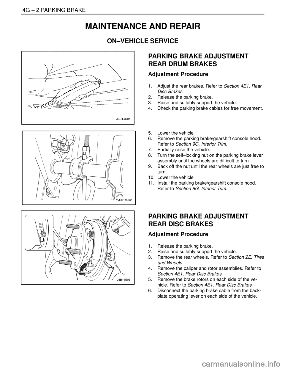
PARKING BRAKE ADJUSTMENT
REAR DRUM BRAKES
Adjustment Procedure
1. Adjust the rear brakes. Refer to Section 4E1, Rear
Disc Brakes.
2. Release the parking brake.
3. Raise and suitably support the vehicle.
4. Check the parking brake cables for free movement.
5. Lower the vehicle
6. Remove the parking brake/gearshift console hood.
Refer to Section 9G, Interior Trim.
7. Partially raise the vehicle.
8. Turn the self–locking nut on the parking brake lever
assembly until the wheels are difficult to turn.
9. Back off the nut until the rear wheels are just free to
turn.
10. Lower the vehicle
11. Install the parking brake/gearshift console hood.
Refer to Section 9G, Interior Trim.
PARKING BRAKE ADJUSTMENT
REAR DISC BRAKES
Adjustment Procedure
1. Release the parking brake.
2. Raise and suitably support the vehicle.
3. Remove the rear wheels. Refer to Section 2E, Tires
and Wheels.
4. Remove the caliper and rotor assemblies. Refer to
Section 4E1, Rear Disc Brakes.
5. Remove the brake rotors on each side of the ve-
hicle. Refer to Section 4E1, Rear Disc Brakes.
6. Disconnect the parking brake cable from the back-
plate operating lever on each side of the vehicle.
Page 1155 of 2643
PARKING BRAKE 4G – 3
DAEWOO V–121 BL4
7. Inspect and replace any parts of doubtful strength
or quality. This can be shown by discoloration from
heat or stress.
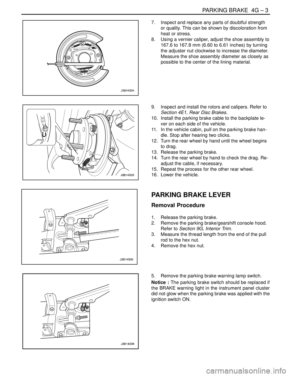
8. Using a vernier caliper, adjust the shoe assembly to
167.6 to 167.8 mm (6.60 to 6.61 inches) by turning
the adjuster nut clockwise to increase the diameter.
Measure the shoe assembly diameter as closely as
possible to the center of the lining material.
9. Inspect and install the rotors and calipers. Refer to
Section 4E1, Rear Disc Brakes.
10. Install the parking brake cable to the backplate le-
ver on each side of the vehicle.
11. In the vehicle cabin, pull on the parking brake han-
dle. Stop after hearing two clicks.
12. Turn the rear wheel by hand until the wheel begins
to drag.
13. Release the parking brake.
14. Turn the rear wheel by hand to check the drag. Re-
adjust the cable, if necessary.
15. Repeat the process for the other rear wheel.
16. Lower the vehicle.
PARKING BRAKE LEVER
Removal Procedure
1. Release the parking brake.
2. Remove the parking brake/gearshift console hood.
Refer to Section 9G, Interior Trim.
3. Measure the thread length from the end of the pull
rod to the hex nut.
4. Remove the hex nut.
5. Remove the parking brake warning lamp switch.
Notice : The parking brake switch should be replaced if
the BRAKE warning light in the instrument panel cluster
did not glow when the parking brake was applied with the
ignition switch ON.
Page 1156 of 2643
4G – 4IPARKING BRAKE
DAEWOO V–121 BL4
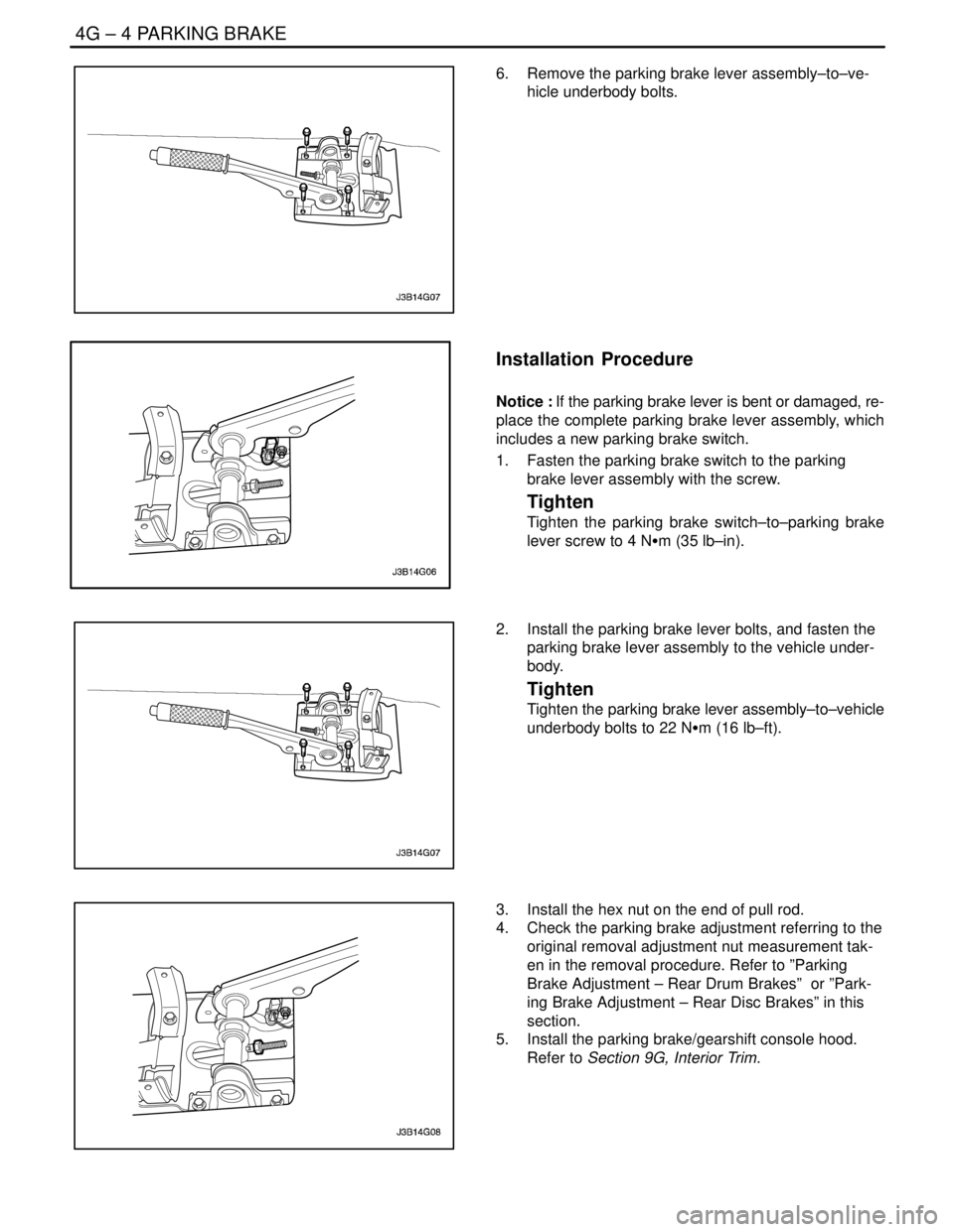
6. Remove the parking brake lever assembly–to–ve-
hicle underbody bolts.
Installation Procedure
Notice : If the parking brake lever is bent or damaged, re-
place the complete parking brake lever assembly, which
includes a new parking brake switch.
1. Fasten the parking brake switch to the parking
brake lever assembly with the screw.
Tighten
Tighten the parking brake switch–to–parking brake
lever screw to 4 NSm (35 lb–in).
2. Install the parking brake lever bolts, and fasten the
parking brake lever assembly to the vehicle under-
body.
Tighten
Tighten the parking brake lever assembly–to–vehicle
underbody bolts to 22 NSm (16 lb–ft).
3. Install the hex nut on the end of pull rod.
4. Check the parking brake adjustment referring to the
original removal adjustment nut measurement tak-
en in the removal procedure. Refer to ”Parking
Brake Adjustment – Rear Drum Brakes” or ”Park-
ing Brake Adjustment – Rear Disc Brakes” in this
section.
5. Install the parking brake/gearshift console hood.
Refer to Section 9G, Interior Trim.
Page 1157 of 2643
PARKING BRAKE 4G – 5
DAEWOO V–121 BL4
PARKING BRAKE CABLE
Removal Procedure
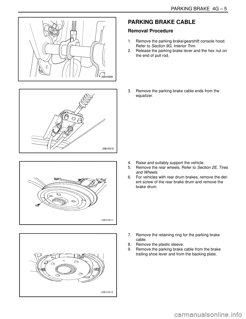
1. Remove the parking brake/gearshift console hood.
Refer to Section 9G, Interior Trim.
2. Release the parking brake lever and the hex nut on
the end of pull rod.
3. Remove the parking brake cable ends from the
equalizer.
4. Raise and suitably support the vehicle.
5. Remove the rear wheels. Refer to Section 2E, Tires
and Wheels.
6. For vehicles with rear drum brakes, remove the det-
ent screw of the rear brake drum and remove the
brake drum.
7. Remove the retaining ring for the parking brake
cable.
8. Remove the plastic sleeve.
9. Remove the parking brake cable from the brake
trailing shoe lever and from the backing plate.
Page 1160 of 2643
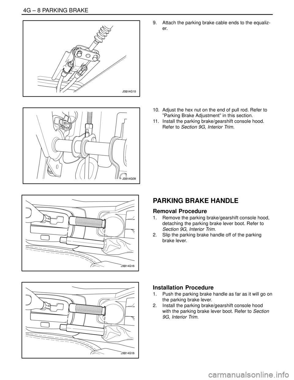
4G – 8IPARKING BRAKE
DAEWOO V–121 BL4
9. Attach the parking brake cable ends to the equaliz-
er.
10. Adjust the hex nut on the end of pull rod. Refer to
”Parking Brake Adjustment” in this section.
11. Install the parking brake/gearshift console hood.
Refer to Section 9G, Interior Trim.
PARKING BRAKE HANDLE
Removal Procedure
1. Remove the parking brake/gearshift console hood,
detaching the parking brake lever boot. Refer to
Section 9G, Interior Trim.
2. Slip the parking brake handle off of the parking
brake lever.
Installation Procedure
1. Push the parking brake handle as far as it will go on
the parking brake lever.
2. Install the parking brake/gearshift console hood
with the parking brake lever boot. Refer to Section
9G, Interior Trim.