Page 2397 of 2643

9L – 18IGLASS AND MIRRORS
DAEWOO V–121 BL4
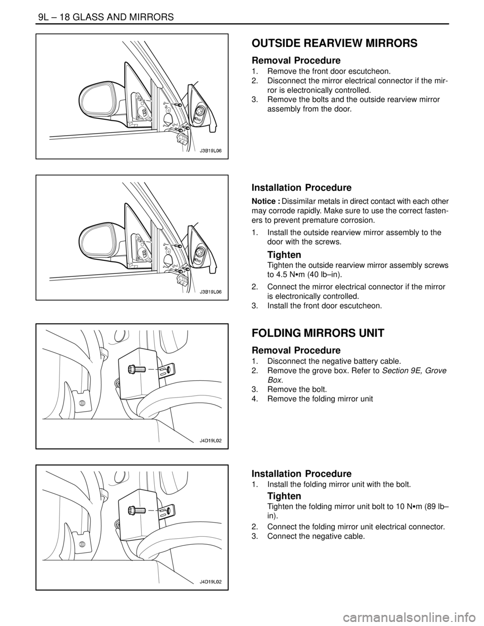
OUTSIDE REARVIEW MIRRORS
Removal Procedure
1. Remove the front door escutcheon.
2. Disconnect the mirror electrical connector if the mir-
ror is electronically controlled.
3. Remove the bolts and the outside rearview mirror
assembly from the door.
Installation Procedure
Notice : Dissimilar metals in direct contact with each other
may corrode rapidly. Make sure to use the correct fasten-
ers to prevent premature corrosion.
1. Install the outside rearview mirror assembly to the
door with the screws.
Tighten
Tighten the outside rearview mirror assembly screws
to 4.5 NSm (40 lb–in).
2. Connect the mirror electrical connector if the mirror
is electronically controlled.
3. Install the front door escutcheon.
FOLDING MIRRORS UNIT
Removal Procedure
1. Disconnect the negative battery cable.
2. Remove the grove box. Refer to Section 9E, Grove
Box.
3. Remove the bolt.
4. Remove the folding mirror unit
Installation Procedure
1. Install the folding mirror unit with the bolt.
Tighten
Tighten the folding mirror unit bolt to 10 NSm (89 lb–
in).
2. Connect the folding mirror unit electrical connector.
3. Connect the negative cable.
Page 2399 of 2643
SECTION : 9M
EXTERIOR TRIM
TABLE OF CONTENTS
SPECIFICATIONS9M–1 . . . . . . . . . . . . . . . . . . . . . . . . . .
Fastener Tightening Specifications 9M–1. . . . . . . . . . .
MAINTENANCE AND REPAIR9M–2 . . . . . . . . . . . . . . .
ON–VEHICLE SERVICE 9M–2. . . . . . . . . . . . . . . . . . . . .
B–Pillar Molding 9M–2. . . . . . . . . . . . . . . . . . . . . . . . . . .
Roof Molding 9M–2. . . . . . . . . . . . . . . . . . . . . . . . . . . . . . Mud Guards 9M–3. . . . . . . . . . . . . . . . . . . . . . . . . . . . . .
Hatchback Rear Spoiler 9M–3. . . . . . . . . . . . . . . . . . . .
GENERAL DESCRIPTION AND SYSTEM
OPERATION9M–5 . . . . . . . . . . . . . . . . . . . . . . . . . . . . . .
Emblems and Lettering 9M–5. . . . . . . . . . . . . . . . . . . . .
Mud Guards 9M–5. . . . . . . . . . . . . . . . . . . . . . . . . . . . . .
SPECIFICATIONS
FASTENER TIGHTENING SPECIFICATIONS
ApplicationNSmLb–FtLb–In
B–Pillar Molding Screws1.3–12
Mud Guard Bolts2–18
Page 2404 of 2643
SECTION : 9N
FRAME AND UNDERBODY
TABLE OF CONTENTS
SPECIFICATIONS9N–1 . . . . . . . . . . . . . . . . . . . . . . . . . .
Fastener Tightening Specifications 9N–1. . . . . . . . . . .
Notchback Underbody Dimensions 9N–2. . . . . . . . . . .
Hatchback Underbody Dimensions 9N–4. . . . . . . . . . .
MAINTENANCE AND REPAIR9N–6 . . . . . . . . . . . . . . .
ON–VEHICLE SERVICE 9N–6. . . . . . . . . . . . . . . . . . . . . Alignment Checking 9N–6. . . . . . . . . . . . . . . . . . . . . . . .
Floor Pan Insulators 9N–6. . . . . . . . . . . . . . . . . . . . . . . .
Engine Under Covers 9N–7. . . . . . . . . . . . . . . . . . . . . .
GENERAL DESCRIPTION AND SYSTEM
OPERATION9N–8 . . . . . . . . . . . . . . . . . . . . . . . . . . . . . .
General Body Construction 9N–8. . . . . . . . . . . . . . . . .
Engine Under Covers 9N–8. . . . . . . . . . . . . . . . . . . . . .
SPECIFICATIONS
FASTENER TIGHTENING SPECIFICATIONS
ApplicationNSmLb–FtLb–In
Engine Under Cover Bolts3.5–31
Page 2412 of 2643

SECTION : 9O
BUMPERS AND FASCIAS
CAUTION : Disconnect the negative battery cable before removing or installing any electrical unit or when a tool
or equipment could easily come in contact with exposed electrical terminals. Disconnecting this cable will help
prevent personal injury and damage to the vehicle. The ignition must also be in LOCK unless otherwise noted.
TABLE OF CONTENTS
SPECIFICATIONS9O–1 . . . . . . . . . . . . . . . . . . . . . . . . . .
Fastener Tightening Specifications 9O–1. . . . . . . . . . .
MAINTENANCE AND REPAIR9O–2 . . . . . . . . . . . . . . .
ON–VEHICLE SERVICE 9O–2. . . . . . . . . . . . . . . . . . . . .
Front Bumper Fascia 9O–2. . . . . . . . . . . . . . . . . . . . . . .
Front Bumper Energy Absorber 9O–3. . . . . . . . . . . . . . Front Bumper Impact Bar 9O–4. . . . . . . . . . . . . . . . . . .
Notchback Rear Bumper Fascia 9O–4. . . . . . . . . . . . .
Hatchback Rear Bumper Fascia 9O–6. . . . . . . . . . . . .
Rear Bumper Impact Bar 9O–7. . . . . . . . . . . . . . . . . . .
GENERAL DESCRIPTION AND SYSTEM
OPERATION9O–9 . . . . . . . . . . . . . . . . . . . . . . . . . . . . . .
Bumpers 9O–9. . . . . . . . . . . . . . . . . . . . . . . . . . . . . . . . .
SPECIFICATIONS
FASTENER TIGHTENING SPECIFICATIONS
ApplicationNSmLb–FtLb–In
Fender–to–Fascia Bolts10–89
Fender–to–Fascia Screws2–18
Front Impact Bar Bolts3929–
Lower Fascia Screws2–18
Luggage Compartment Fascia Bolts10–89
Luggage Compartment Fascia Screws2–18
Rear Wheel Well Fascia Bolts2–18
Page 2413 of 2643
9O – 2IBUMPERS AND FASCIAS
DAEWOO V–121 BL4
MAINTENANCE AND REPAIR
ON–VEHICLE SERVICE
FRONT BUMPER FASCIA
Removal Procedure
1. Disconnect the negative battery cable.
2. Remove the front wheel well splash shields. Refer
to Section 9R, Body Front End.
3. Remove the fog lamps and the headlamps. Refer to
Section 9B, Lighting Systems.
4. Remove the fender–to–fascia bolts and the screws.
5. Remove the lower fascia clips.
6. Remove the upper fascia clips.
7. Remove the front bumper fascia.
Page 2414 of 2643
BUMPERS AND FASCIAS 9O – 3
DAEWOO V–121 BL4
Installation Procedure
1. Install the front bumper fascia.
Notice : Dissimilar metals in direct contact with each other
may corrode rapidly. Make sure to use the correct fasten-
ers to prevent premature corrosion.
2. Install the upper fascia screws.
3. Install the lower fascia clips.
4. Install the fender–to–fascia bolts and the screws.
Tighten
Tighten the fender–to–fascia bolts to 10 NSm (89 lb–
in).
Tighten the fender–to–fascia screws to 2 NSm (18 lb–
in).
5. Install the headlamps and the fog lamps. Refer to
Section 9B, Lighting Systems.
6. Install the front wheel well splash shields. Refer to
Section 9B, Lighting Systems.
7. Connect the negative battery cable.
FRONT BUMPER ENERGY
ABSORBER
Removal Procedure
1. Remove the front bumper fascia. Refer to ”Front
Bumper Fascia” in this section.
2. Remove the energy absorber.
Page 2415 of 2643

9O – 4IBUMPERS AND FASCIAS
DAEWOO V–121 BL4
Installation Procedure
1. Install the energy absorber.
2. Install the front bumper fascia. Refer to ”Front
Bumper Fascia” in this section.
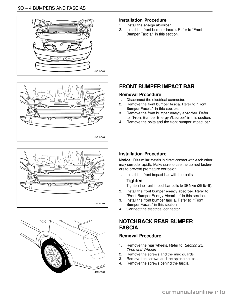
FRONT BUMPER IMPACT BAR
Removal Procedure
1. Disconnect the electrical connector.
2. Remove the front bumper fascia. Refer to ”Front
Bumper Fascia” in this section.
3. Remove the front bumper energy absorber. Refer
to ”Front Bumper Energy Absorber” in this section.
4. Remove the bolts and the front bumper impact bar.
Installation Procedure
Notice : Dissimilar metals in direct contact with each other
may corrode rapidly. Make sure to use the correct fasten-
ers to prevent premature corrosion.
1. Install the front impact bar with the bolts.
Tighten
Tighten the front impact bar bolts to 39 NSm (29 lb–ft).
2. Install the front bumper energy absorber. Refer to
”Front Bumper Energy Absorber” in this section.
3. Install the front bumper fascia. Refer to ”Front
Bumper Fascia” in this section.
4. Connect the electrical connector.
NOTCHBACK REAR BUMPER
FASCIA
Removal Procedure
1. Remove the rear wheels. Refer to Section 2E,
Tires and Wheels.
2. Remove the screws and the mud guards.
3. Remove the screws and the splash shields.
4. Remove the screws behind the fascia.
Page 2416 of 2643
BUMPERS AND FASCIAS 9O – 5
DAEWOO V–121 BL4
5. Remove the luggage compartment rear guarter trim
panels. Refer to Section 9G, Interior Trim.
6. Remove the bolts and the nuts in the luggage
compartment.
7. Remove the bolts and the screws.
8. Remove the rear bumper fascia.
Installation Procedure
1. Install the rear bumper fascia with the bolts and the
screws.
2. Install the bolts and the nuts in the luggage
compartment.
3. Install the luggage compartment rear guarter trim
panels. Refer to Section 9G, Interior Trim.