Page 2440 of 2643
9P – 20IDOORS
DAEWOO V–121 BL4
Installation Procedure
1. Install the front door opening weatherstrip.
2. Install the kick panel, the front rocker panel, and the
lower B–pillar trim panel. Refer to Section 9G, Inte-
rior Trim.
REAR DOOR OPENING
WEATHERSTRIP
Removal Procedure
1. Remove the rear rocker panel and the lower B–pil-
lar trim panel. Refer to Section 9G, Interior Trim.
2. Remove the rear door opening weatherstrip.
Installation Procedure
1. Install the rear door opening weatherstrip.
2. Install the rear rocker panel and the lower B–pillar
trim panel. Refer to Section 9G, Interior Trim.
DOOR SEAL TRIM
(Front Door Shown, Rear Door Similar)
Removal Procedure
1. Remove the door trim panel. Refer to Section 9G,
Interior Trim.
2. Remove the door seal trim.
Page 2441 of 2643
DOORS 9P – 21
DAEWOO V–121 BL4
Installation Procedure
1. Install the door seal trim.
Notice : Dissimilar metals in direct contact with each other
may corrode rapidly. Make sure to use the correct fasten-
ers to prevent premature corrosion.
2. Install the door trim panel. Refer to Section 9G,
Interior Trim.
DOOR LOCK STRIKER
(Front Door Shown, Rear Door Similar)
Removal Procedure
1. Remove the screws and the door lock striker.
(Front door shown, rear door similar.)
Installation Procedure
Notice : Dissimilar metals in direct contact with each other
may corrode rapidly. Make sure to use the correct fasten-
ers to prevent premature corrosion.
1. Install the screws and the door lock striker.
Tighten
Tighten the door lock striker screws to 24 NSm (18 lb–
ft).
Page 2443 of 2643
DOORS 9P – 23
DAEWOO V–121 BL4
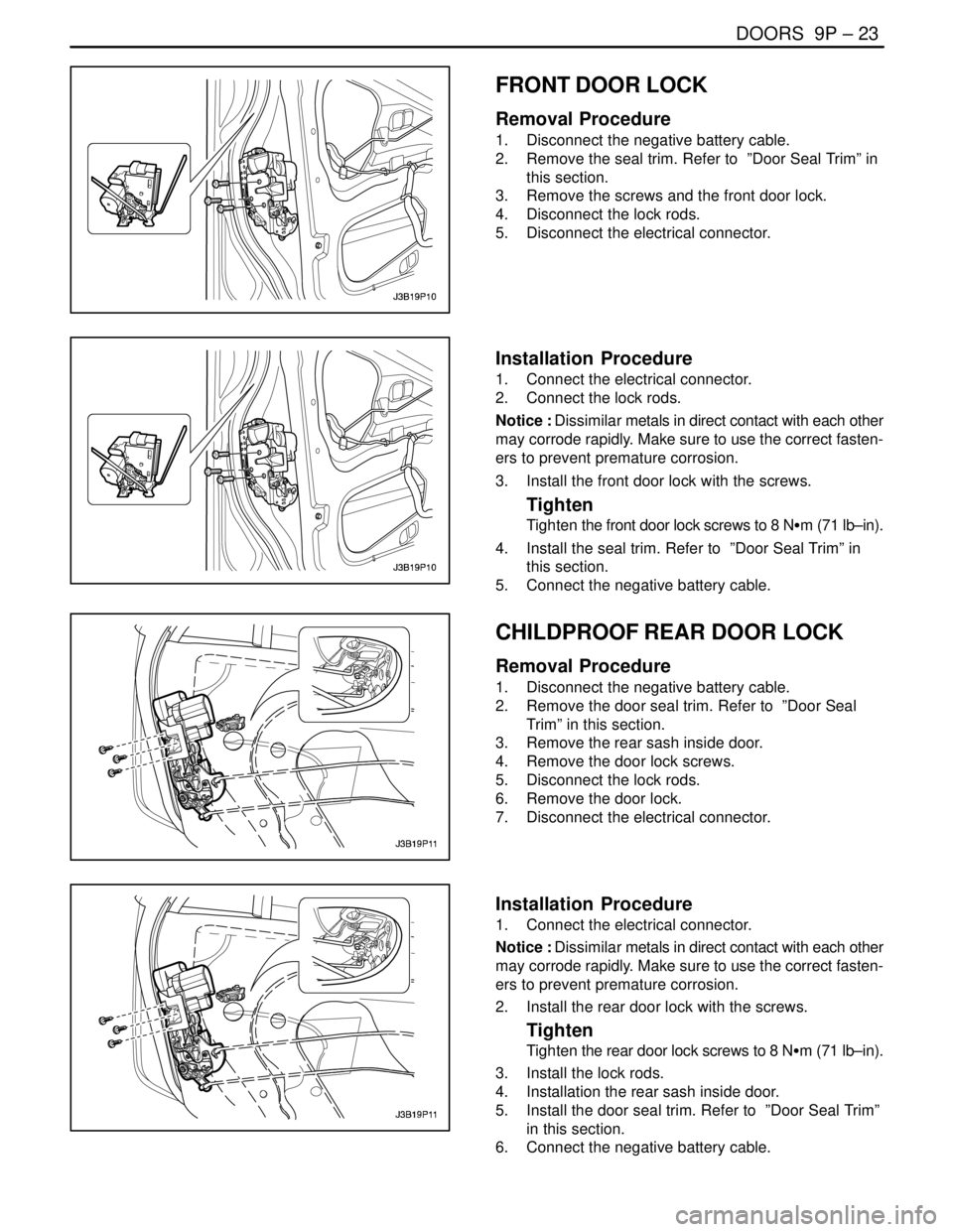
FRONT DOOR LOCK
Removal Procedure
1. Disconnect the negative battery cable.
2. Remove the seal trim. Refer to ”Door Seal Trim” in
this section.
3. Remove the screws and the front door lock.
4. Disconnect the lock rods.
5. Disconnect the electrical connector.
Installation Procedure
1. Connect the electrical connector.
2. Connect the lock rods.
Notice : Dissimilar metals in direct contact with each other
may corrode rapidly. Make sure to use the correct fasten-
ers to prevent premature corrosion.
3. Install the front door lock with the screws.
Tighten
Tighten the front door lock screws to 8 NSm (71 lb–in).
4. Install the seal trim. Refer to ”Door Seal Trim” in
this section.
5. Connect the negative battery cable.
CHILDPROOF REAR DOOR LOCK
Removal Procedure
1. Disconnect the negative battery cable.
2. Remove the door seal trim. Refer to ”Door Seal
Trim” in this section.
3. Remove the rear sash inside door.
4. Remove the door lock screws.
5. Disconnect the lock rods.
6. Remove the door lock.
7. Disconnect the electrical connector.
Installation Procedure
1. Connect the electrical connector.
Notice : Dissimilar metals in direct contact with each other
may corrode rapidly. Make sure to use the correct fasten-
ers to prevent premature corrosion.
2. Install the rear door lock with the screws.
Tighten
Tighten the rear door lock screws to 8 NSm (71 lb–in).
3. Install the lock rods.
4. Installation the rear sash inside door.
5. Install the door seal trim. Refer to ”Door Seal Trim”
in this section.
6. Connect the negative battery cable.
Page 2444 of 2643
9P – 24IDOORS
DAEWOO V–121 BL4
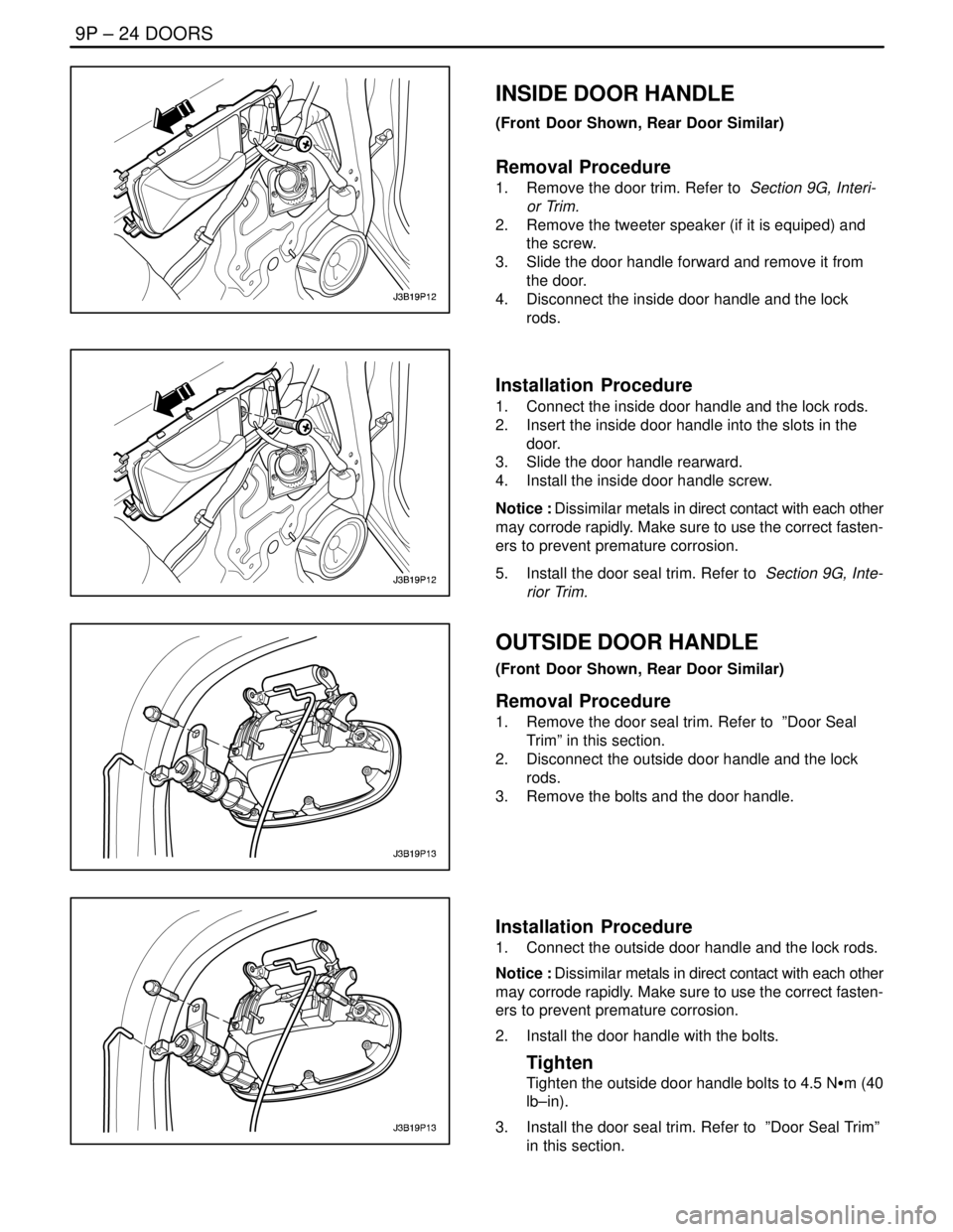
INSIDE DOOR HANDLE
(Front Door Shown, Rear Door Similar)
Removal Procedure
1. Remove the door trim. Refer to Section 9G, Interi-
or Trim.
2. Remove the tweeter speaker (if it is equiped) and
the screw.
3. Slide the door handle forward and remove it from
the door.
4. Disconnect the inside door handle and the lock
rods.
Installation Procedure
1. Connect the inside door handle and the lock rods.
2. Insert the inside door handle into the slots in the
door.
3. Slide the door handle rearward.
4. Install the inside door handle screw.
Notice : Dissimilar metals in direct contact with each other
may corrode rapidly. Make sure to use the correct fasten-
ers to prevent premature corrosion.
5. Install the door seal trim. Refer to Section 9G, Inte-
rior Trim.
OUTSIDE DOOR HANDLE
(Front Door Shown, Rear Door Similar)
Removal Procedure
1. Remove the door seal trim. Refer to ”Door Seal
Trim” in this section.
2. Disconnect the outside door handle and the lock
rods.
3. Remove the bolts and the door handle.
Installation Procedure
1. Connect the outside door handle and the lock rods.
Notice : Dissimilar metals in direct contact with each other
may corrode rapidly. Make sure to use the correct fasten-
ers to prevent premature corrosion.
2. Install the door handle with the bolts.
Tighten
Tighten the outside door handle bolts to 4.5 NSm (40
lb–in).
3. Install the door seal trim. Refer to ”Door Seal Trim”
in this section.
Page 2445 of 2643
DOORS 9P – 25
DAEWOO V–121 BL4
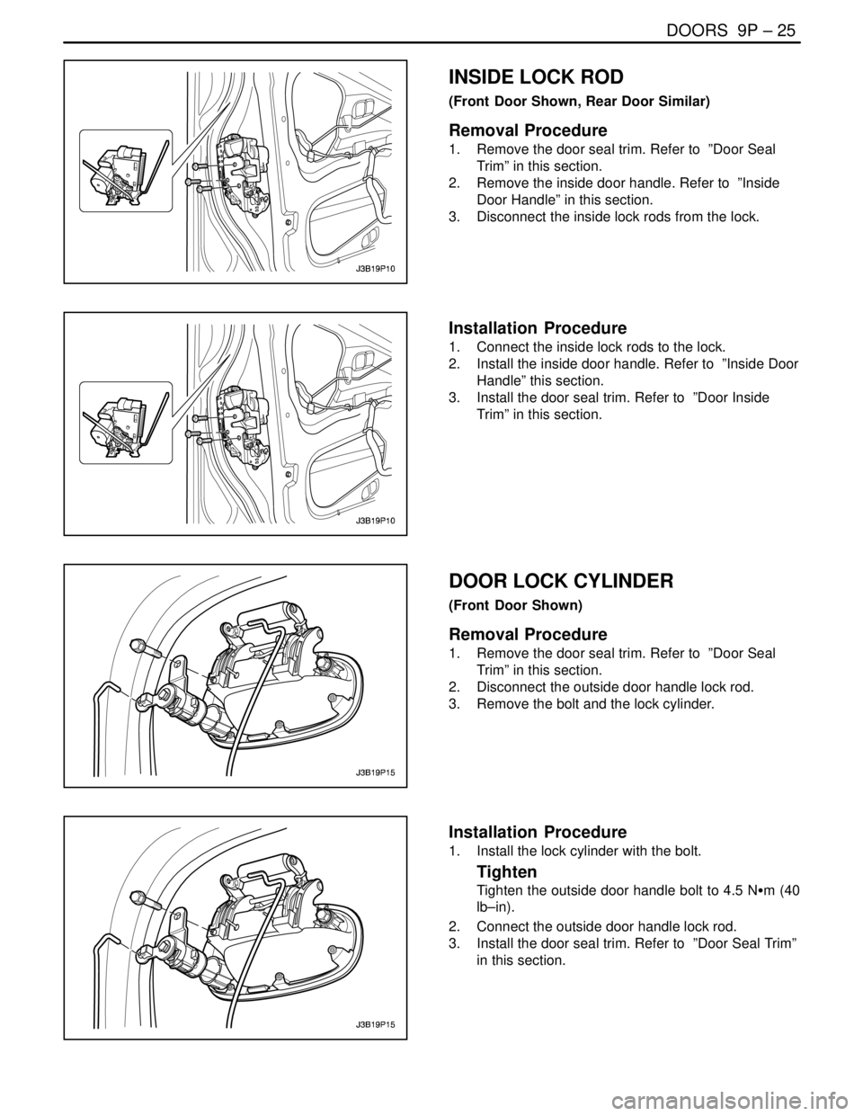
INSIDE LOCK ROD
(Front Door Shown, Rear Door Similar)
Removal Procedure
1. Remove the door seal trim. Refer to ”Door Seal
Trim” in this section.
2. Remove the inside door handle. Refer to ”Inside
Door Handle” in this section.
3. Disconnect the inside lock rods from the lock.
Installation Procedure
1. Connect the inside lock rods to the lock.
2. Install the inside door handle. Refer to ”Inside Door
Handle” this section.
3. Install the door seal trim. Refer to ”Door Inside
Trim” in this section.
DOOR LOCK CYLINDER
(Front Door Shown)
Removal Procedure
1. Remove the door seal trim. Refer to ”Door Seal
Trim” in this section.
2. Disconnect the outside door handle lock rod.
3. Remove the bolt and the lock cylinder.
Installation Procedure
1. Install the lock cylinder with the bolt.
Tighten
Tighten the outside door handle bolt to 4.5 NSm (40
lb–in).
2. Connect the outside door handle lock rod.
3. Install the door seal trim. Refer to ”Door Seal Trim”
in this section.
Page 2446 of 2643
9P – 26IDOORS
DAEWOO V–121 BL4
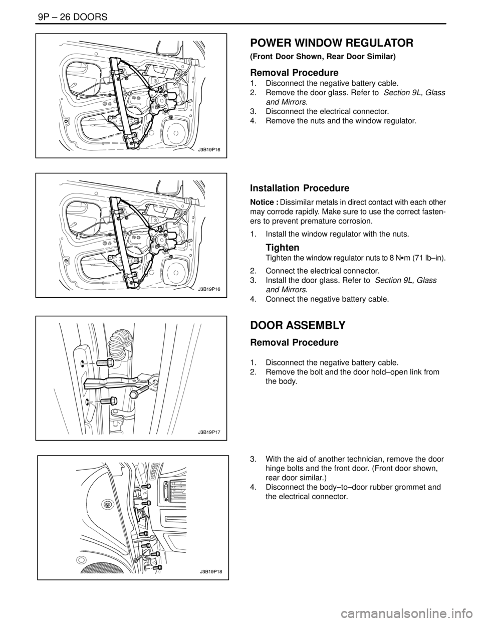
POWER WINDOW REGULATOR
(Front Door Shown, Rear Door Similar)
Removal Procedure
1. Disconnect the negative battery cable.
2. Remove the door glass. Refer to Section 9L, Glass
and Mirrors.
3. Disconnect the electrical connector.
4. Remove the nuts and the window regulator.
Installation Procedure
Notice : Dissimilar metals in direct contact with each other
may corrode rapidly. Make sure to use the correct fasten-
ers to prevent premature corrosion.
1. Install the window regulator with the nuts.
Tighten
Tighten the window regulator nuts to 8 NSm (71 lb–in).
2. Connect the electrical connector.
3. Install the door glass. Refer to Section 9L, Glass
and Mirrors.
4. Connect the negative battery cable.
DOOR ASSEMBLY
Removal Procedure
1. Disconnect the negative battery cable.
2. Remove the bolt and the door hold–open link from
the body.
3. With the aid of another technician, remove the door
hinge bolts and the front door. (Front door shown,
rear door similar.)
4. Disconnect the body–to–door rubber grommet and
the electrical connector.
Page 2447 of 2643
DOORS 9P – 27
DAEWOO V–121 BL4
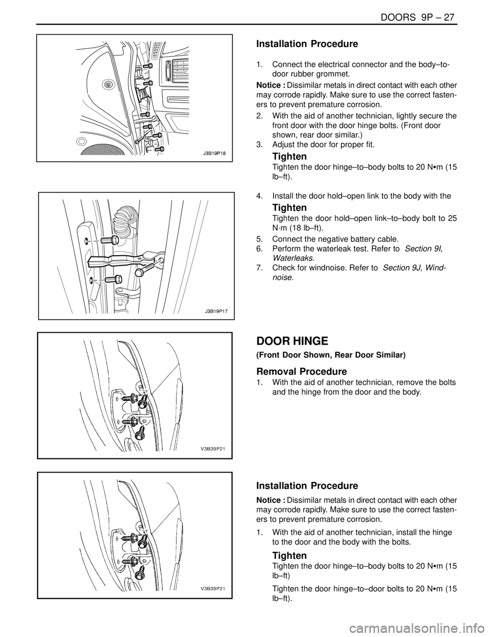
Installation Procedure
1. Connect the electrical connector and the body–to-
door rubber grommet.
Notice : Dissimilar metals in direct contact with each other
may corrode rapidly. Make sure to use the correct fasten-
ers to prevent premature corrosion.
2. With the aid of another technician, lightly secure the
front door with the door hinge bolts. (Front door
shown, rear door similar.)
3. Adjust the door for proper fit.
Tighten
Tighten the door hinge–to–body bolts to 20 NSm (15
lb–ft).
4. Install the door hold–open link to the body with the
Tighten
Tighten the door hold–open link–to–body bolt to 25
N·m (18 lb–ft).
5. Connect the negative battery cable.
6. Perform the waterleak test. Refer to Section 9I,
Waterleaks.
7. Check for windnoise. Refer to Section 9J, Wind-
noise.
DOOR HINGE
(Front Door Shown, Rear Door Similar)
Removal Procedure
1. With the aid of another technician, remove the bolts
and the hinge from the door and the body.
Installation Procedure
Notice : Dissimilar metals in direct contact with each other
may corrode rapidly. Make sure to use the correct fasten-
ers to prevent premature corrosion.
1. With the aid of another technician, install the hinge
to the door and the body with the bolts.
Tighten
Tighten the door hinge–to–body bolts to 20 NSm (15
lb–ft)
Tighten the door hinge–to–door bolts to 20 NSm (15
lb–ft).
Page 2448 of 2643
9P – 28IDOORS
DAEWOO V–121 BL4
DOOR HOLD–OPEN LINK
(Front Door Shown, Rear Door Similar)
Removal Procedure
1. Remove the door seal trim. Refer to ”Door Seal
Trim” in this section.
2. Remove the bolts on the door and on the body.
3. Remove the door hold–open link.
Installation Procedure
Notice : Dissimilar metals in direct contact with each other
may corrode rapidly. Make sure to use the correct fasten-
ers to prevent premature corrosion.
1. Install the door hold–open link to the door and the
body with the bolts.
Tighten
Tighten the door hold–open link–to–body bolt to 25
NSm (18 lb–ft).
Tighten the door hold–open link–to–door bolts to 9
NSm (80 lb–in).
2. Install the door seal trim. Refer to ”Door Seal Trim”
in this section.