2004 DAEWOO LACETTI timing belt
[x] Cancel search: timing beltPage 17 of 2643
0B – 10IGENERAL INFORMATION
DAEWOO V–121 BL4
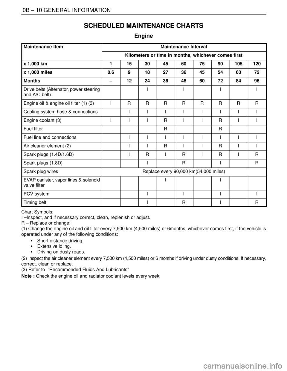
SCHEDULED MAINTENANCE CHARTS
Engine
Maintenance ItemMaintenance Interval
Kilometers or time in months, whichever comes first
x 1,000 km1153045607590105120
x 1,000 miles0.6918273645546372
Months–1224364860728496
Drive belts (Alternator, power steering
and A/C belt)IIII
Engine oil & engine oil filter (1) (3)IRRRRRRRR
Cooling system hose & connectionsIIIIIIII
Engine coolant (3)IIIRIIRII
Fuel filterRR
Fuel line and connectionsIIIIIIII
Air cleaner element (2)IIRIIRII
Spark plugs (1.4D/1.6D)IRIRIRIR
Spark plugs (1.8D)IRIR
Spark plug wiresReplace every 90,000 km(54,000 miles)
EVAP canister, vapor lines & solenoid
valve filterII
PCV systemIIII
Timing beltlRlR
Chart Symbols:
I –Inspect, and if necessary correct, clean, replenish or adjust.
R – Replace or change:
(1) Change the engine oil and oil filter every 7,500 km (4,500 miles) or 6months, whichever comes first, if the vehicle is
operated under any of the following conditions:
S Short distance driving.
S Extensive idling.
S Driving on dusty roads.
(2) Inspect the air cleaner element every 7,500 km (4,500 miles) or 6 months if driving under dusty conditions. If necessary,
correct, clean or replace.
(3) Refer to ”Recommended Fluids And Lubricants”
Note : Check the engine oil and radiator coolant levels every week.
Page 40 of 2643
1A – 8IGENERAL ENGINE INFORMATION
DAEWOO V–121 BL4
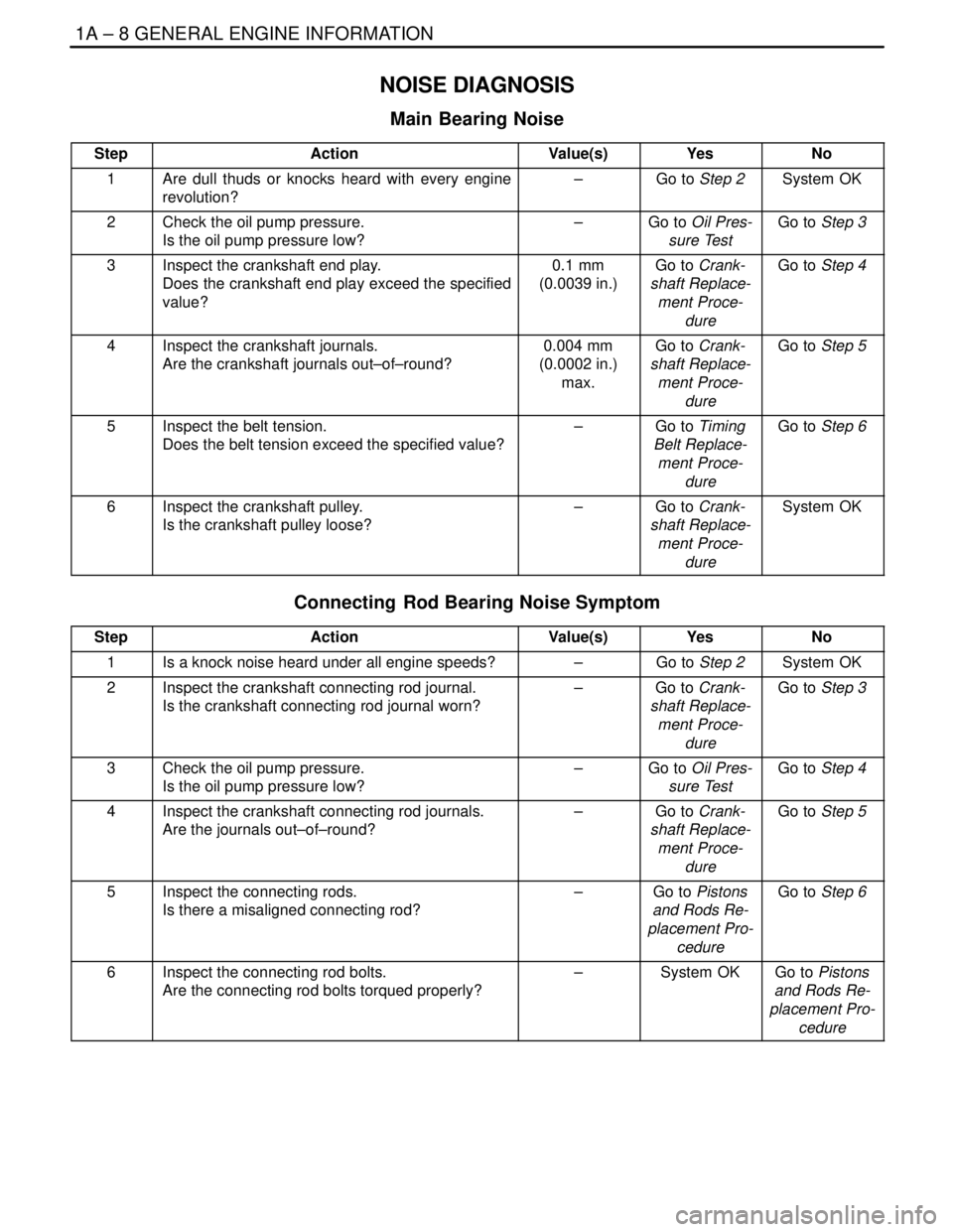
NOISE DIAGNOSIS
Main Bearing Noise
StepActionValue(s)YesNo
1Are dull thuds or knocks heard with every engine
revolution?–Go to Step 2System OK
2Check the oil pump pressure.
Is the oil pump pressure low?–Go to Oil Pres-
sure TestGo to Step 3
3Inspect the crankshaft end play.
Does the crankshaft end play exceed the specified
value?0.1 mm
(0.0039 in.)Go to Crank-
shaft Replace-
ment Proce-
dureGo to Step 4
4Inspect the crankshaft journals.
Are the crankshaft journals out–of–round?0.004 mm
(0.0002 in.)
max.Go to Crank-
shaft Replace-
ment Proce-
dureGo to Step 5
5Inspect the belt tension.
Does the belt tension exceed the specified value?–Go to Timing
Belt Replace-
ment Proce-
dureGo to Step 6
6Inspect the crankshaft pulley.
Is the crankshaft pulley loose?–Go to Crank-
shaft Replace-
ment Proce-
dureSystem OK
Connecting Rod Bearing Noise Symptom
StepActionValue(s)YesNo
1Is a knock noise heard under all engine speeds?–Go to Step 2System OK
2Inspect the crankshaft connecting rod journal.
Is the crankshaft connecting rod journal worn?–Go to Crank-
shaft Replace-
ment Proce-
dureGo to Step 3
3Check the oil pump pressure.
Is the oil pump pressure low?–Go to Oil Pres-
sure TestGo to Step 4
4Inspect the crankshaft connecting rod journals.
Are the journals out–of–round?–Go to Crank-
shaft Replace-
ment Proce-
dureGo to Step 5
5Inspect the connecting rods.
Is there a misaligned connecting rod?–Go to Pistons
and Rods Re-
placement Pro-
cedureGo to Step 6
6Inspect the connecting rod bolts.
Are the connecting rod bolts torqued properly?–System OKGo to Pistons
and Rods Re-
placement Pro-
cedure
Page 44 of 2643
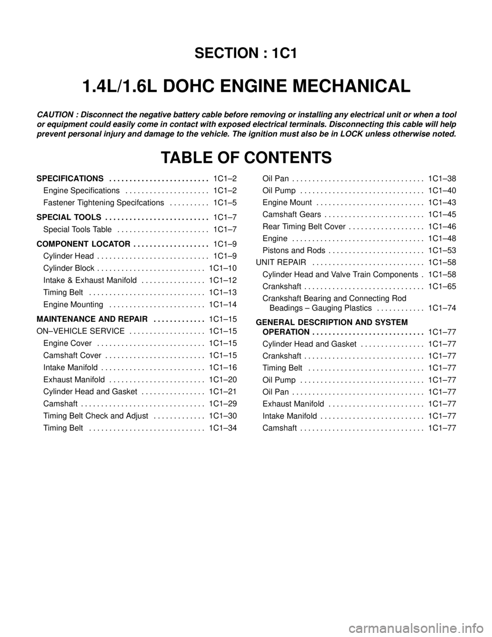
SECTION : 1C1
1.4L/1.6L DOHC ENGINE MECHANICAL
CAUTION : Disconnect the negative battery cable before removing or installing any electrical unit or when a tool
or equipment could easily come in contact with exposed electrical terminals. Disconnecting this cable will help
prevent personal injury and damage to the vehicle. The ignition must also be in LOCK unless otherwise noted.
TABLE OF CONTENTS
SPECIFICATIONS1C1–2 . . . . . . . . . . . . . . . . . . . . . . . . .
Engine Specifications 1C1–2. . . . . . . . . . . . . . . . . . . . .
Fastener Tightening Specifcations 1C1–5. . . . . . . . . .
SPECIAL TOOLS1C1–7 . . . . . . . . . . . . . . . . . . . . . . . . . .
Special Tools Table 1C1–7. . . . . . . . . . . . . . . . . . . . . . .
COMPONENT LOCATOR1C1–9 . . . . . . . . . . . . . . . . . . .
Cylinder Head 1C1–9. . . . . . . . . . . . . . . . . . . . . . . . . . . .
Cylinder Block 1C1–10. . . . . . . . . . . . . . . . . . . . . . . . . . .
Intake & Exhaust Manifold 1C1–12. . . . . . . . . . . . . . . .
Timing Belt 1C1–13. . . . . . . . . . . . . . . . . . . . . . . . . . . . .
Engine Mounting 1C1–14. . . . . . . . . . . . . . . . . . . . . . . .
MAINTENANCE AND REPAIR1C1–15 . . . . . . . . . . . . .
ON–VEHICLE SERVICE 1C1–15. . . . . . . . . . . . . . . . . . .
Engine Cover 1C1–15. . . . . . . . . . . . . . . . . . . . . . . . . . .
Camshaft Cover 1C1–15. . . . . . . . . . . . . . . . . . . . . . . . .
Intake Manifold 1C1–16. . . . . . . . . . . . . . . . . . . . . . . . . .
Exhaust Manifold 1C1–20. . . . . . . . . . . . . . . . . . . . . . . .
Cylinder Head and Gasket 1C1–21. . . . . . . . . . . . . . . .
Camshaft 1C1–29. . . . . . . . . . . . . . . . . . . . . . . . . . . . . . .
Timing Belt Check and Adjust 1C1–30. . . . . . . . . . . . .
Timing Belt 1C1–34. . . . . . . . . . . . . . . . . . . . . . . . . . . . . Oil Pan 1C1–38. . . . . . . . . . . . . . . . . . . . . . . . . . . . . . . . .
Oil Pump 1C1–40. . . . . . . . . . . . . . . . . . . . . . . . . . . . . . .
Engine Mount 1C1–43. . . . . . . . . . . . . . . . . . . . . . . . . . .
Camshaft Gears 1C1–45. . . . . . . . . . . . . . . . . . . . . . . . .
Rear Timing Belt Cover 1C1–46. . . . . . . . . . . . . . . . . . .
Engine 1C1–48. . . . . . . . . . . . . . . . . . . . . . . . . . . . . . . . .
Pistons and Rods 1C1–53. . . . . . . . . . . . . . . . . . . . . . . .
UNIT REPAIR 1C1–58. . . . . . . . . . . . . . . . . . . . . . . . . . . .
Cylinder Head and Valve Train Components 1C1–58.
Crankshaft 1C1–65. . . . . . . . . . . . . . . . . . . . . . . . . . . . . .
Crankshaft Bearing and Connecting Rod
Beadings – Gauging Plastics 1C1–74. . . . . . . . . . . .
GENERAL DESCRIPTION AND SYSTEM
OPERATION1C1–77 . . . . . . . . . . . . . . . . . . . . . . . . . . . .
Cylinder Head and Gasket 1C1–77. . . . . . . . . . . . . . . .
Crankshaft 1C1–77. . . . . . . . . . . . . . . . . . . . . . . . . . . . . .
Timing Belt 1C1–77. . . . . . . . . . . . . . . . . . . . . . . . . . . . .
Oil Pump 1C1–77. . . . . . . . . . . . . . . . . . . . . . . . . . . . . . .
Oil Pan 1C1–77. . . . . . . . . . . . . . . . . . . . . . . . . . . . . . . . .
Exhaust Manifold 1C1–77. . . . . . . . . . . . . . . . . . . . . . . .
Intake Manifold 1C1–77. . . . . . . . . . . . . . . . . . . . . . . . . .
Camshaft 1C1–77. . . . . . . . . . . . . . . . . . . . . . . . . . . . . . .
Page 48 of 2643

1.4L/1.6L DOHC ENGINE MECHANICAL 1C1 – 5
DAEWOO V–121 BL4
FASTENER TIGHTENING SPECIFCATIONS
ApplicationNSmLb–FtLb–In
Air Cleaner Housing Bolts10–89
Camshaft Cap Bolts1612–
Camshaft Cover Nuts10–89
Connecting Rod Bearing Cap Bolts25
+ 30° + 15°18
+ 30° + 15°–
Coolant Temperature Sensor2015–
Crankshaft Bearing Cap Bolts50
+ 45° + 15°37
+ 45°+ 15°–
Crankshaft Cover Nuts5~8–44~71
Crankshaft Pulley Bolt95 NSm
+ 30° + 15°––
Cylinder Head Bolts (Cylinder Head Mounting Bolts)25 + 70°
+ 70° + 50°18 + 70°
+ 70° + 50°–
Direct Ignition System Coil Mounting Bolts10–89
Direct Ignition System Coil Mounting Bracket Bolts10–89
Engine Mount Attaching Bolts3022–
Engine Mount Bracket Attaching Bolts/Nuts5037–
Exhaust Camshaft Gear Bolt67.549–
Exhaust Flex Pipe–to–Catalytic Converter or Connecting Pipe
Retaining Nut3526–
Exhaust Flex Pipe–to–Exhaust Manifold Retaining Nuts3526–
Exhaust Gas Recirculation Valve Adapter Bolts2518–
Exhaust Manifold Heat Shield Bolts1511–
Exhaust Manifold Retaining Nuts2518–
Flexible Plate Bolts6044–
Flexible Plate Inspection Cover Bolts10–89
Flywheel Bolts35
+ 30° + 15°25
+ 30° + 15°–
Flywheel Inspection Cover Bolts12–106
Front Timing Belt Cover Bolts (Upper and Lower)10–89
Fuel Rail Assembly Retaining Bolts2518–
Fuel Rail Retaining Bolts2518–
Generator Upper Retaining Bolt2015–
Intake Camshaft Gear Bolt67.549–
Intake Manifold Retaining Bolts/Nuts2518–
Intake Manifold Support Bracket Lower Bolt2518–
Intake Manifold Support Bracket Upper Bolts2518–
Lower Front Timing Belt Cover Bolts10–89
Oil Pan Flange Bolts7555–
Oil Pan Retaining Bolts10–89
Oil Pan Drain Plug3526–
OIl Pressure Switch4030–
Page 49 of 2643
1C1 – 6I1.4L/1.6L DOHC ENGINE MECHANICAL
DAEWOO V–121 BL4
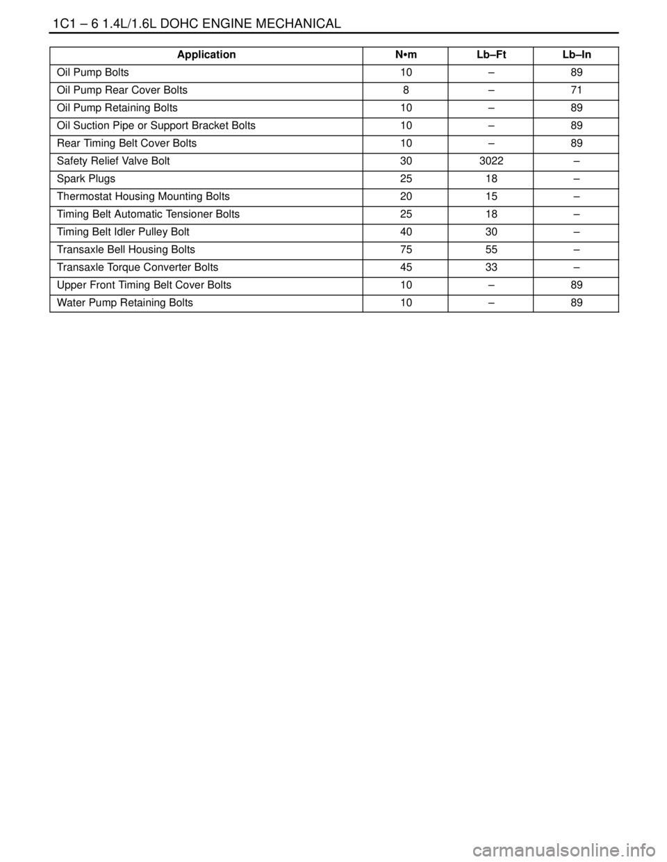
Application Lb–InLb–Ft NSm
Oil Pump Bolts10–89
Oil Pump Rear Cover Bolts8–71
Oil Pump Retaining Bolts10–89
Oil Suction Pipe or Support Bracket Bolts10–89
Rear Timing Belt Cover Bolts10–89
Safety Relief Valve Bolt303022–
Spark Plugs2518–
Thermostat Housing Mounting Bolts2015–
Timing Belt Automatic Tensioner Bolts2518–
Timing Belt Idler Pulley Bolt4030–
Transaxle Bell Housing Bolts7555–
Transaxle Torque Converter Bolts4533–
Upper Front Timing Belt Cover Bolts10–89
Water Pump Retaining Bolts10–89
Page 50 of 2643
1.4L/1.6L DOHC ENGINE MECHANICAL 1C1 – 7
DAEWOO V–121 BL4
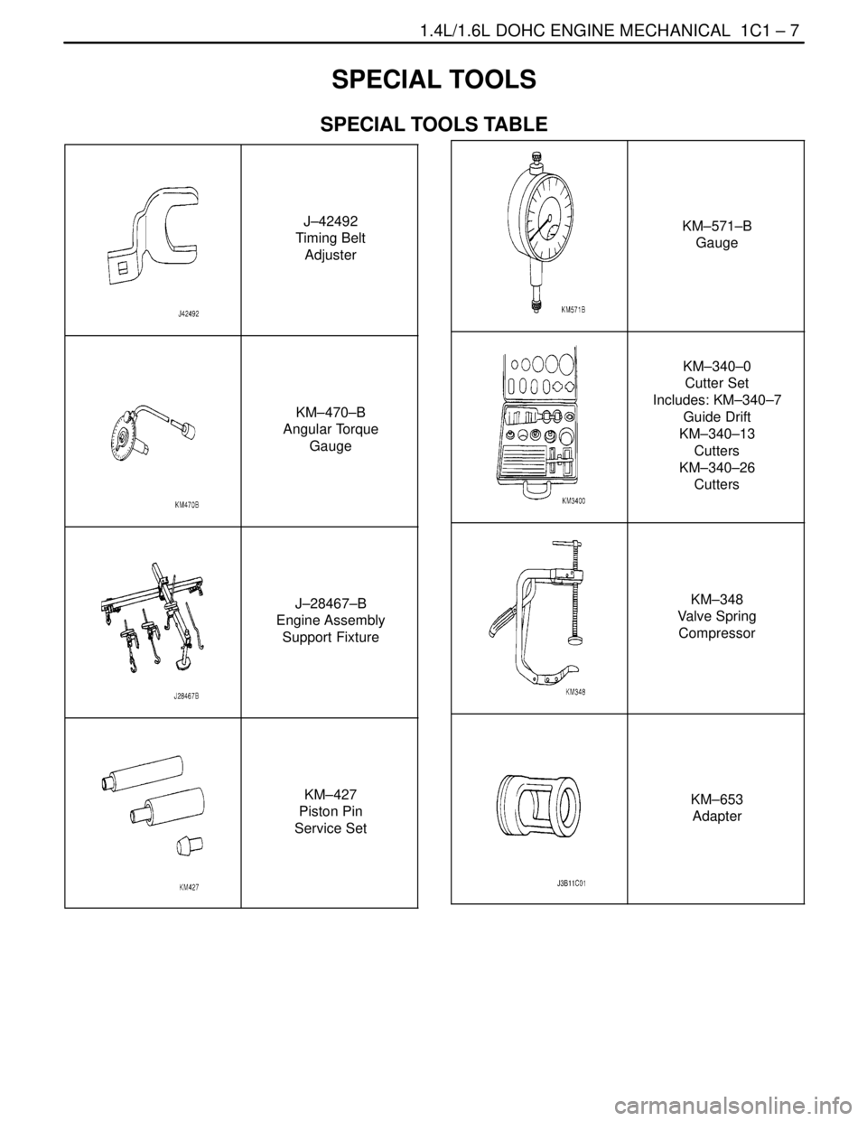
SPECIAL TOOLS
SPECIAL TOOLS TABLE
J–42492
Timing Belt
Adjuster
KM–470–B
Angular Torque
Gauge
J–28467–B
Engine Assembly
Support Fixture
KM–427
Piston Pin
Service Set
KM–571–B
Gauge
KM–340–0
Cutter Set
Includes: KM–340–7
Guide Drift
KM–340–13
Cutters
KM–340–26
Cutters
KM–348
Valve Spring
Compressor
KM–653
Adapter
Page 56 of 2643

1.4L/1.6L DOHC ENGINE MECHANICAL 1C1 – 13
DAEWOO V–121 BL4
TIMING BELT
1. Water Pump Sealing
2. Water Pump
3. Timing Belt Rear Cover
4. Camshaft Position Sensor
5. Auto Temsioner
6. Camshaft Gear
7. Idler pulley8. Crankshaft Gear
9. Torque Roll Axis Support
10. Timing Belt
11. Timing Belt Front Upper Cover
12. Timing Belt Front Lower Cover
13. Crankshaft Pulley
14. Crankshaft Position Sensor
Page 64 of 2643
1.4L/1.6L DOHC ENGINE MECHANICAL 1C1 – 21
DAEWOO V–121 BL4
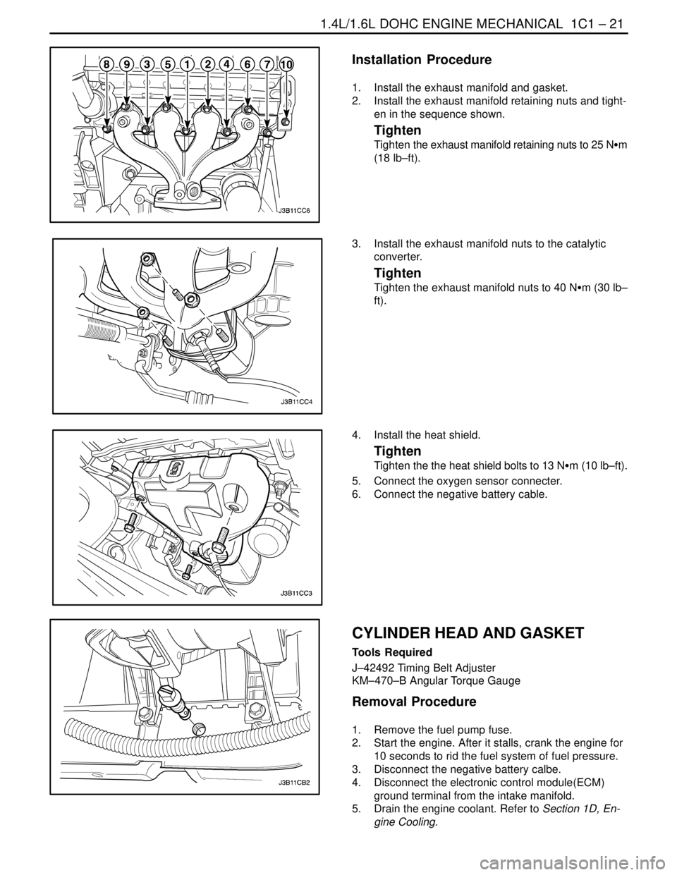
Installation Procedure
1. Install the exhaust manifold and gasket.
2. Install the exhaust manifold retaining nuts and tight-
en in the sequence shown.
Tighten
Tighten the exhaust manifold retaining nuts to 25 NSm
(18 lb–ft).
3. Install the exhaust manifold nuts to the catalytic
converter.
Tighten
Tighten the exhaust manifold nuts to 40 NSm (30 lb–
ft).
4. Install the heat shield.
Tighten
Tighten the the heat shield bolts to 13 NSm (10 lb–ft).
5. Connect the oxygen sensor connecter.
6. Connect the negative battery cable.
CYLINDER HEAD AND GASKET
Tools Required
J–42492 Timing Belt Adjuster
KM–470–B Angular Torque Gauge
Removal Procedure
1. Remove the fuel pump fuse.
2. Start the engine. After it stalls, crank the engine for
10 seconds to rid the fuel system of fuel pressure.
3. Disconnect the negative battery calbe.
4. Disconnect the electronic control module(ECM)
ground terminal from the intake manifold.
5. Drain the engine coolant. Refer to Section 1D, En-
gine Cooling.