Page 2362 of 2643
9H – 6ISEATS
DAEWOO V–121 BL4
Installation Procedure
Notice : Dissimilar metals in direct contact with each other
may corrode rapidly. Make sure to use the correct fasten-
ers to prevent premature corrosion.
1. Install the lumbar support lever.
HEIGHT ADJUSTMENT KNOBS
Removal Procedure
1. Remove the height adjustment knob.
Installation Procedure
Notice : Dissimilar metals in direct contact with each other
may corrode rapidly. Make sure to use the correct fasten-
ers to prevent premature corrosion.
1. Install the height adjustment knob.
FRONT SEAT TRIM
Removal Procedure
1. Remove the front bucket seat from the vehicle. Re-
fer to ”Front Bucket Seats” in this section.
2. Remove the screws and the front seat trim.
Page 2363 of 2643
SEATS 9H – 7
DAEWOO V–121 BL4
Installation Procedure
Notice : Dissimilar metals in direct contact with each other
may corrode rapidly. Make sure to use the correct fasten-
ers to prevent premature corrosion.
1. Install the front seat trim with the screws.
Tighten
Tighten the front seat trim screws to 12 NSm (106 lb–
in).
2. Install the front bucket seat in the vehicle. Refer to
”Front Bucket Seats” in this section.
HEAD RESTRAINT
Removal Procedure
1. Press in the head restraint adjust button and re-
move the head restraint from the seatback.
2. Insert two flat head screwdrivers down the front and
back side of the guide sleeves.
3. With the screwdrivers, press in the retaining latches
and remove the guide sleeves.
Installation Procedure
1. Install the guide sleeves into the seatback and
press them down to engage the guide sleeve re-
taining latches.
2. Install the head restraint into the guide sleeves.
Page 2365 of 2643

SEATS 9H – 9
DAEWOO V–121 BL4
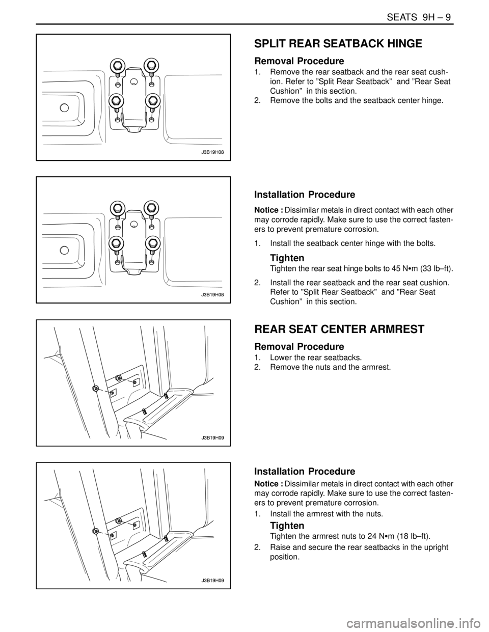
SPLIT REAR SEATBACK HINGE
Removal Procedure
1. Remove the rear seatback and the rear seat cush-
ion. Refer to ”Split Rear Seatback” and ”Rear Seat
Cushion” in this section.
2. Remove the bolts and the seatback center hinge.
Installation Procedure
Notice : Dissimilar metals in direct contact with each other
may corrode rapidly. Make sure to use the correct fasten-
ers to prevent premature corrosion.
1. Install the seatback center hinge with the bolts.
Tighten
Tighten the rear seat hinge bolts to 45 NSm (33 lb–ft).
2. Install the rear seatback and the rear seat cushion.
Refer to ”Split Rear Seatback” and ”Rear Seat
Cushion” in this section.
REAR SEAT CENTER ARMREST
Removal Procedure
1. Lower the rear seatbacks.
2. Remove the nuts and the armrest.
Installation Procedure
Notice : Dissimilar metals in direct contact with each other
may corrode rapidly. Make sure to use the correct fasten-
ers to prevent premature corrosion.
1. Install the armrest with the nuts.
Tighten
Tighten the armrest nuts to 24 NSm (18 lb–ft).
2. Raise and secure the rear seatbacks in the upright
position.
Page 2366 of 2643
9H – 10ISEATS
DAEWOO V–121 BL4
SEAT COVERS
Removal Procedure
1. Remove the seatback and/or cushion. Refer to
”Front Seatback”, ”Front Seat Cushion”, ”Split Rear
Seatback”, and/or ”Rear Seat Cushion” in this sec-
tion.
2. Remove the hog rings from the seatback and/or the
cushion.
3. Remove the seat cover from the seatback and/or
the cushion.
Installation Procedure
1. Install the seat cover onto the seatback and/or the
cushion with new hog rings.
2. Install the seatback and/or the seat cushion. Refer
to ”Front Seatback”, ”Front Seat Cushion”, ”Split
Rear Seatback”, and/or ”Rear Seat Cushion” in
this section.
CHILD SEAT ANCHORAGE
Removal Procedure
1. Remove child seat anchorage cover.
2. Remove bolt and the child seat anchorage.
Installation Procedure
1. Install the child seat anchorage with the bolt.
Tighten
Tighten the child seat anchorage bolt to 10 NSm (89
lb–in).
2. Install the child seat anchorage cover.
Page 2369 of 2643

SECTION : 9I
WATERLEAKS
TABLE OF CONTENTS
SPECIFICATIONS9I–1 . . . . . . . . . . . . . . . . . . . . . . . . . . .
Recommended Materials for Waterleak Repairs 9I–1.
Watertest Stand Specifications 9I–1. . . . . . . . . . . . . . .
DIAGNOSIS9I–2 . . . . . . . . . . . . . . . . . . . . . . . . . . . . . . . . . Waterleak Diagnosis 9I–2. . . . . . . . . . . . . . . . . . . . . . . .
MAINTENANCE AND REPAIR9I–5 . . . . . . . . . . . . . . . .
ON–VEHICLE SERVICE 9I–5. . . . . . . . . . . . . . . . . . . . . .
Waterleak Repair 9I–5. . . . . . . . . . . . . . . . . . . . . . . . . . .
SPECIFICATIONS
RECOMMENDED MATERIALS FOR WATERLEAK
REPAIRS
Leak Areas Repair Materials
Windshield, back windowUrethane adhesive, caulking kit, or the equivalent
Metal jointsBrushable seam sealer which can be painted
Ventilation ducts3Mnv Auto Bedding and Glazing Compound or the equiva-
lent
Small cracks and pin holes3Mnv Drip–Check Sealer or the equivalent
Large holes3Mnv Automotive Joint and Seam Sealer
Weatherstrips3Mnv 08011 Weatherstrip Adhesive or the equivalent
Bolts, studs, and screwsStrip caulk
WATERTEST STAND SPECIFICATIONS
ApplicationDescription
Nozzle TypeFull jet spray nozzle #1/2 GG–25 or equivalent with a 60°
included angle
Nozzle HeightApproximately 1 600 mm (63.0 in.) from the floor
Volume of Flow14L (3.7 gal) per minute
Pressure155 kPa (22.5 psi) measured at the nozzle
Windshield and A–Pillar Test Stand PositionApproximately 30° down, 45° toward the rear, and aimed
at the corner of the windshield
B–Pillar Test Stand PositionApproximately 30° down, 45° toward the rear, and aimed
at the center of the rear door
Back Window and Rear Deck Lid Test Stand PositionApproximately 30° down, 30° toward the front and aimed
approximately 610 mm (24.0 in.) from the corner of the
back window
Page 2371 of 2643
WATERLEAKS 9I – 3
DAEWOO V–121 BL4
3. Perform the watertest stand leak test. Refer to ”Wa-
tertest Stand Specifications” in this section.
4. If the local water pressure does not allow the re-
quired water pressure of 155 kPa (22.5 psi), moveboth stands closer to the vehicle so that the water
spray overlaps.
Localized Testing (Spot Test)
1. Do localized testing with a water hose or an air
hose.
2. Begin testing by spraying the air or the water at the
base of the suspected leak area. Continue spraying
the air or the water upward until the leak is found.
Water Hose Test
1. Place another person inside the vehicle in order to
detect the location of the leak.
2. Use a water hose without a nozzle.
3. Begin spraying the water at the base of the sus-
pected leak area. Continue spraying the water up-
ward until the leak is found.
Page 2375 of 2643

SECTION : 9J
WINDNOISE
TABLE OF CONTENTS
DIAGNOSIS9J–1 . . . . . . . . . . . . . . . . . . . . . . . . . . . . . . . . .
Windnoise Diagnosis 9J–1. . . . . . . . . . . . . . . . . . . . . . . .
MAINTENANCE AND REPAIR9J–2 . . . . . . . . . . . . . . . . ON–VEHICLE SERVICE 9J–2. . . . . . . . . . . . . . . . . . . . . .
Windnoise Repair 9J–2. . . . . . . . . . . . . . . . . . . . . . . . . . .
DIAGNOSIS
WINDNOISE DIAGNOSIS
CAUTION : An assistant should drive the vehicle
while the technician checks for the location of the
windnoise, in order to prevent personal injury or ve-
hicle damage.
A test drive in the vehicle is necessary to accurately deter-
mine the location of the windnoise. Often there is a primary
leak and secondary leaks. Failure to repair all leaks will
only reduce the windnoise, not eliminate it.
During the test drive the technician should bring the follow-
ing items to aid in determining the location of the wind-
noise.
S A mechanics stethoscope or vacuum hose
S Masking tape
S Strip caulk
S A china marking pencil
S A screwdriver
Perform the following steps in order to conduct the road
test:
1. Choose a route that includes smooth straight
streets that run in all four directions (north, south,
east, and west).
2. Choose streets with little traffic or noise that would
interfere with the test.
3. Drive the vehicle at the speeds at which the noise
was noticed by the customer or until the noise is
produced. Do not exceed legal speed limits.
4. The windnoise is external if any of the following
conditions occur:
S The windnoise is caused by the wind.S The windnoise can be heard with the door glass
lowered and while the vehicle is being driven.
S The windnoise is eliminated when tape is placed
over various moldings and gaps.
5. Internal windnoise is air leaving the vehicle and
should be repaired in the following manner.
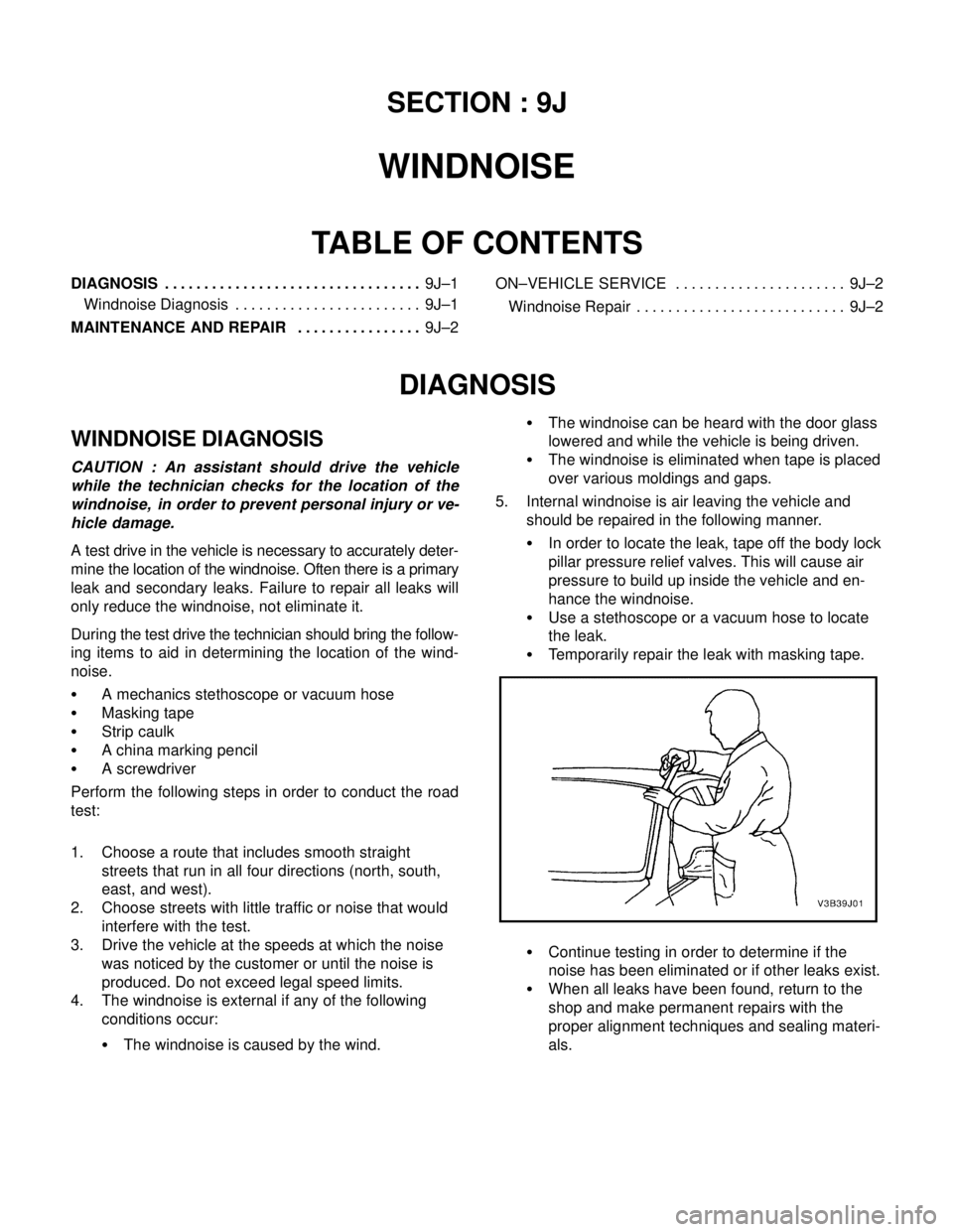
S In order to locate the leak, tape off the body lock
pillar pressure relief valves. This will cause air
pressure to build up inside the vehicle and en-
hance the windnoise.
S Use a stethoscope or a vacuum hose to locate
the leak.
S Temporarily repair the leak with masking tape.
S Continue testing in order to determine if the
noise has been eliminated or if other leaks exist.
S When all leaks have been found, return to the
shop and make permanent repairs with the
proper alignment techniques and sealing materi-
als.
Page 2376 of 2643
9J – 2IWINDNOISE
DAEWOO V–121 BL4
MAINTENANCE AND REPAIR
ON–VEHICLE SERVICE
WINDNOISE REPAIR
Windnoise leak repairs are very similar to waterleak re-
pairs. Refer to Section 9I, Waterleaks. The actual proce-
dure depends on the type of seal being repaired.
Leaks around the door opening weatherstrips do not al-
ways indicate a faulty weatherstrip. A door or window ad-
justment may resolve the condition. Refer to Section 9P,
Doors or Section 9L, Glass and Mirrors.