Page 2338 of 2643

AUDIO SYSTEMS 9F – 9
DAEWOO V–121 BL4
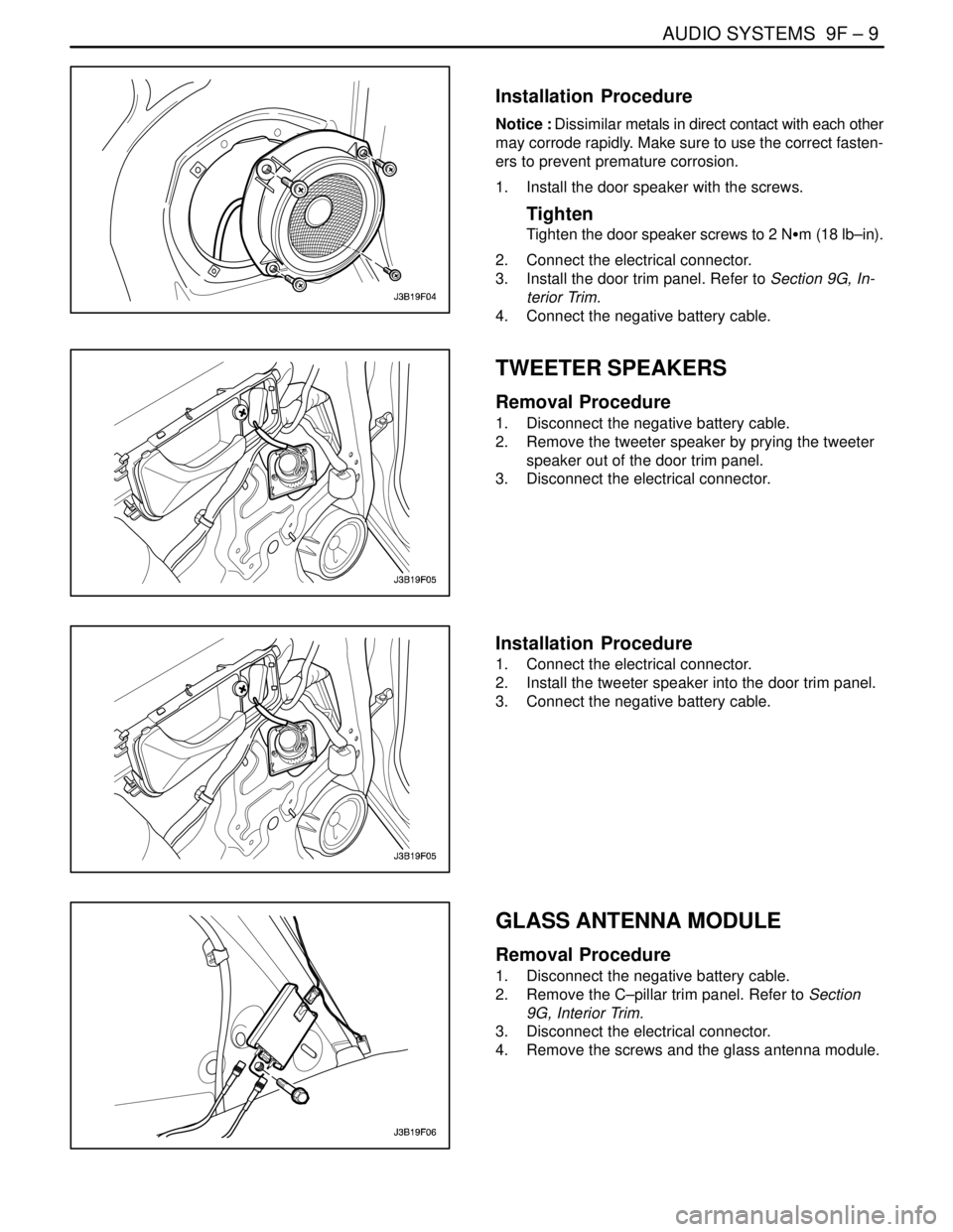
Installation Procedure
Notice : Dissimilar metals in direct contact with each other
may corrode rapidly. Make sure to use the correct fasten-
ers to prevent premature corrosion.
1. Install the door speaker with the screws.
Tighten
Tighten the door speaker screws to 2 NSm (18 lb–in).
2. Connect the electrical connector.
3. Install the door trim panel. Refer to Section 9G, In-
terior Trim.
4. Connect the negative battery cable.
TWEETER SPEAKERS
Removal Procedure
1. Disconnect the negative battery cable.
2. Remove the tweeter speaker by prying the tweeter
speaker out of the door trim panel.
3. Disconnect the electrical connector.
Installation Procedure
1. Connect the electrical connector.
2. Install the tweeter speaker into the door trim panel.
3. Connect the negative battery cable.
GLASS ANTENNA MODULE
Removal Procedure
1. Disconnect the negative battery cable.
2. Remove the C–pillar trim panel. Refer to Section
9G, Interior Trim.
3. Disconnect the electrical connector.
4. Remove the screws and the glass antenna module.
Page 2339 of 2643

9F – 10IAUDIO SYSTEMS
DAEWOO V–121 BL4
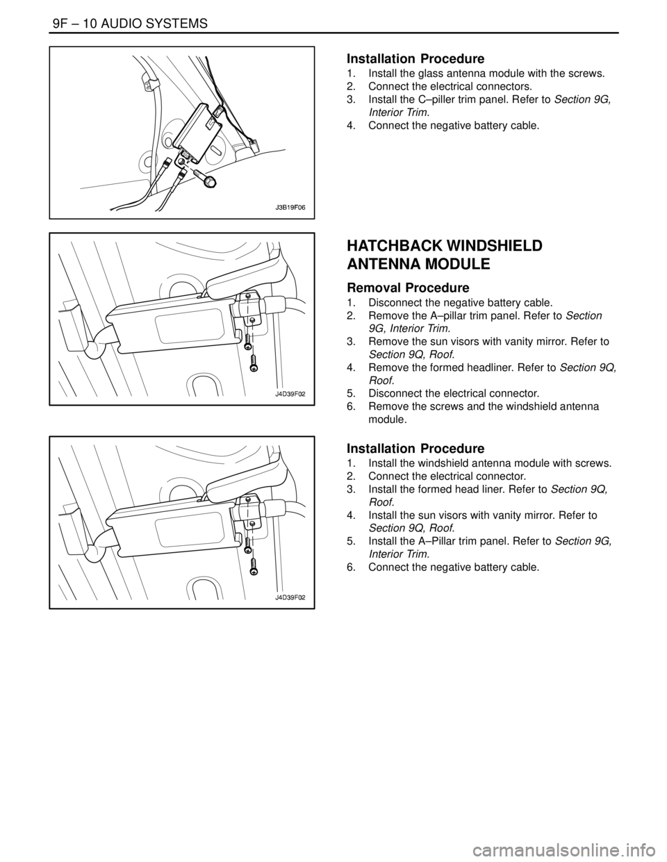
Installation Procedure
1. Install the glass antenna module with the screws.
2. Connect the electrical connectors.
3. Install the C–piller trim panel. Refer to Section 9G,
Interior Trim.
4. Connect the negative battery cable.
HATCHBACK WINDSHIELD
ANTENNA MODULE
Removal Procedure
1. Disconnect the negative battery cable.
2. Remove the A–pillar trim panel. Refer to Section
9G, Interior Trim.
3. Remove the sun visors with vanity mirror. Refer to
Section 9Q, Roof.
4. Remove the formed headliner. Refer to Section 9Q,
Roof.
5. Disconnect the electrical connector.
6. Remove the screws and the windshield antenna
module.
Installation Procedure
1. Install the windshield antenna module with screws.
2. Connect the electrical connector.
3. Install the formed head liner. Refer to Section 9Q,
Roof.
4. Install the sun visors with vanity mirror. Refer to
Section 9Q, Roof.
5. Install the A–Pillar trim panel. Refer to Section 9G,
Interior Trim.
6. Connect the negative battery cable.
Page 2341 of 2643

SECTION : 9G
INTERIOR TRIM
CAUTION : Disconnect the negative battery cable before removing or installing any electrical unit or when a tool
or equipment could easily come in contact with exposed electrical terminals. Disconnecting this cable will help
prevent personal injury and damage to the vehicle. The ignition must also be in LOCK unless otherwise noted.
TABLE OF CONTENTS
SPECIFICATIONS9G–1 . . . . . . . . . . . . . . . . . . . . . . . . . .
Fastener Tightening Specifications 9G–1. . . . . . . . . . .
SPECIAL TOOLS9G–2 . . . . . . . . . . . . . . . . . . . . . . . . . . .
Special Tools Table 9G–2. . . . . . . . . . . . . . . . . . . . . . . .
MAINTENANCE AND REPAIR9G–3 . . . . . . . . . . . . . . .
ON–VEHICLE SERVICE 9G–3. . . . . . . . . . . . . . . . . . . . .
Front Door Trim Panel 9G–3. . . . . . . . . . . . . . . . . . . . . .
Rear Door Trim Panel 9G–4. . . . . . . . . . . . . . . . . . . . . .
A–pillar Trim Panel 9G–4. . . . . . . . . . . . . . . . . . . . . . . . .
Upper B–pillar Trim Panel 9G–5. . . . . . . . . . . . . . . . . . .
Lower B–pillar Trim Panel 9G–5. . . . . . . . . . . . . . . . . . .
C–pillar Trim Panel 9G–6. . . . . . . . . . . . . . . . . . . . . . . . .
Deck Lid Sill Plate Cover 9G–6. . . . . . . . . . . . . . . . . . .
Front Rocker Trim Panel 9G–7. . . . . . . . . . . . . . . . . . . .
Rear Rocker Trim Panel 9G–7. . . . . . . . . . . . . . . . . . . .
Front Wheelhouse Trim 9G–8. . . . . . . . . . . . . . . . . . . . .
Rear Wheelhouse Trim 9G–8. . . . . . . . . . . . . . . . . . . . .
Floor Console 9G–9. . . . . . . . . . . . . . . . . . . . . . . . . . . . . Floor Carpet 9G–10. . . . . . . . . . . . . . . . . . . . . . . . . . . . .
Luggage Compartment Rear Low Cover 9G–11. . . . .
Luggage Compartment Wheelhouse Trim
Panel 9G–12. . . . . . . . . . . . . . . . . . . . . . . . . . . . . . . . . .
Driver’s Side Knee Bolster 9G–12. . . . . . . . . . . . . . . . .
Hatchback Door Lower Garnish Molding 9G–13. . . . .
Hatchback Door Upper Garnish Molding 9G–14. . . . .
Luggage Compartment Wheelhouse Trim Panel
(HATCHBACK) 9G–14. . . . . . . . . . . . . . . . . . . . . . . . .
Luggage Compartment Rear Trim Panel 9G–14. . . . .
GENERAL DESCRIPTION AND SYSTEM
OPERATION9G–16 . . . . . . . . . . . . . . . . . . . . . . . . . . . . .
Interior Trim Panels 9G–16. . . . . . . . . . . . . . . . . . . . . . .
Pressure Relief Vent 9G–16. . . . . . . . . . . . . . . . . . . . . .
Floor Console 9G–16. . . . . . . . . . . . . . . . . . . . . . . . . . . .
Floor Carpet 9G–16. . . . . . . . . . . . . . . . . . . . . . . . . . . . .
Rear Compartment Security Cover
(HATCHBACK) 9G–16. . . . . . . . . . . . . . . . . . . . . . . . .
SPECIFICATIONS
FASTENER TIGHTENING SPECIFICATIONS
ApplicationNSmLb–FtLb–In
Door Trim Panel Screws2.5–22
Driver’s Side Knee Bolster Mounting Bolts10–89
Floor Console Screws2.5–22
Gearshift Housing Bolts8–70
Hood Latch Release Handle Mounting Screw3–27
Seat Belt Anchor Bolt3828–
Page 2345 of 2643
INTERIOR TRIM 9G – 5
DAEWOO V–121 BL4
Installation Procedure
1. Install the A–pillar trim panel.
UPPER B–PILLAR TRIM PANEL
Removal Procedure
1. Remove the lower B–pillar trim panel. Refer to
”Lower B–Pillar Trim Panel” In this Section.
2. Remove the bolt and the upper front seat belt an-
chor.
3. Reposition the upper portion of the lower B–pillar
trim panel.
4. Pry off the upper B–pillar trim panel.
Installation Procedure
1. Install the upper B–pillar trim panel.
2. Install the upper portion of the lower B–pillar trim
panel to its original position.
3. Install the upper front seat belt anchor with the bolt.
Tighten
Tighten the seat belt anchor bolt to 38 NSm (28 lb–ft).
4. Install the lower B–pillar trim panel. Refer to ”Lower
B–Pillar Trim Panel” In this Section.
LOWER B–PILLAR TRIM PANEL
Removal Procedure
1. Reposition the rear portion of the front rocker trim
panel and the front portion of the rear rocker trim
panel.
2. Remove the lower B–pillar trim panel.
Page 2346 of 2643
9G – 6IINTERIOR TRIM
DAEWOO V–121 BL4
Installation Procedure
1. Install the lower B–pillar trim panel.
2. Install the front rocker trim panel and the rear rock-
er trim panel to their original positions.
C–PILLAR TRIM PANEL
Removal Procedure
1. Remove the C–pillar trim panel.
Installation Procedure
1. Install the C–pillar trim panel.
DECK LID SILL PLATE COVER
Removal Procedure
1. Lower the rear seatback.
2. Remove the C–pillar trim panel.
3. Remove the rear seat belts. Refer to Section 8A,
Seat Belts.
4. Remove the child seat anchorage. Refer to Section
9H, Child Seat Anchorage.
5. Remove the plastic retaining clips and the deck lid
sill plate cover.
Page 2347 of 2643
INTERIOR TRIM 9G – 7
DAEWOO V–121 BL4
Installation Procedure
1. Install the rear deck lid sill plate cover with the plas-
tic retaining clips.
2. Install the child seat anchorage. Refer to Section
9H, Child Seat Anchorage.
3. Install the rear seat belts. Refer to Section 9A, Seat
Belts.
4. Install the C–pillar trim panel.
5. Install the rear seat. Refer to Section 9H, Seats.
FRONT ROCKER TRIM PANEL
Removal Procedure
1. Remove the front rocker trim panel.
Installation Procedure
1. Install the front rocker trim panel.
REAR ROCKER TRIM PANEL
Removal Procedure
1. Reposition the rear seat cushion.
2. Remove the rear rocker trim panel.
Page 2348 of 2643
9G – 8IINTERIOR TRIM
DAEWOO V–121 BL4
Installation Procedure
1. Install the rear rocker trim panel.
2. Install the rear seat cushion to its original position.
FRONT WHEELHOUSE TRIM
Removal Procedure
1. Remove the screws and the front wheelhouse trim.
Installation Procedure
1. Install the front wheelhouse trim with the screws.
REAR WHEELHOUSE TRIM
Removal Procedure
1. Remove the rear seat. Refer to Section 9H, Seats.
2. Remove the seat belt bolt.
3. Remove the screws and the rear wheelhouse trim.
Page 2349 of 2643
INTERIOR TRIM 9G – 9
DAEWOO V–121 BL4
Installation Procedure
1. Install the rear wheelhouse trim with the screws.
2. Install the seat belt bolt.
3. Install the rear seat. Refer to Section 9H, Seats.
FLOOR CONSOLE
Removal Procedure
1. Disconnect the negative battery cable.
2. Remove the screw from the rear portion of the floor
console.
3. Remove the screws from the front portion of the
floor console.
4. Remove the floor console.
5. Disconnect the electrical connectors.
Installation Procedure
1. Connect the electrical connectors.
2. Install the floor console.
3. Install the front portion of the floor console with the
screws.