2004 DAEWOO LACETTI Section 6
[x] Cancel search: Section 6Page 2377 of 2643

SECTION : 9K
SQUEAKS AND RATTLES
TABLE OF CONTENTS
DIAGNOSIS9K–1 . . . . . . . . . . . . . . . . . . . . . . . . . . . . . . . .
Squeak and Rattle Diagnosis 9K–1. . . . . . . . . . . . . . . .
MAINTENANCE AND REPAIR9K–3 . . . . . . . . . . . . . . . ON–VEHICLE SERVICE 9K–3. . . . . . . . . . . . . . . . . . . . .
Squeak and Rattle Repair 9K–3. . . . . . . . . . . . . . . . . . .
DIAGNOSIS
SQUEAK AND RATTLE DIAGNOSIS
Rattle Coming From the Side Rail
ChecksAction
Check the brake lines.S Tap lightly on the brake lines and listen for a rattle.
S Install plastic tie straps to secure the brake lines
tightly together.
Rattle Under Vehicle at Higher RPM
ChecksAction
Check for heat shield contact with the underbody.S Raise the vehicle and perform a visual inspection.
S Bend the heat shield slightly to gain clearance from
the underbody.
Squeak From the Front of the Vehicle in Cold Weather
ChecksAction
Check the front stabilizer shaft insulators.S While the vehicle is cold, perform a test drive and
achieve full front suspension travel by driving through
a dip in the road.
S Remove the insulators and wrap teflon tape around
the stabilizer shaft. Reinstall the insulators over the
tape.
Thump From Rear of Vehicle on Bumps
ChecksAction
Check for a properly secured spare tire in the rear
compartment.S Open the rear compartment and perform a visual
inspection of the spare tire and the tools.
S Tightly secure the spare tire and all tools.
S Perform a road test to verify that the noise is elimi-
nated.
Page 2380 of 2643

SECTION : 9L
GLASS AND MIRRORS
CAUTION : Disconnect the negative battery cable before removing or installing any electrical unit or when a tool
or equipment could easily come in contact with exposed electrical terminals. Disconnecting this cable will help
prevent personal injury and damage to the vehicle. The ignition must also be in LOCK unless otherwise noted.
TABLE OF CONTENTS
SPECIFICATIONS9L–2 . . . . . . . . . . . . . . . . . . . . . . . . . . .
Fastener Tightening Specifications 9L–2. . . . . . . . . . . .
SPECIAL TOOLS9L–2 . . . . . . . . . . . . . . . . . . . . . . . . . . . .
Special Tools Table 9L–2. . . . . . . . . . . . . . . . . . . . . . . . .
SCHEMATIC AND ROUTING DIAGRAMS9L–3 . . . . . .
Defogger System 9L–3. . . . . . . . . . . . . . . . . . . . . . . . . . .
Electric Control OSRV (Outside Rear View)
Mirror System 9L–4. . . . . . . . . . . . . . . . . . . . . . . . . . . .
DIAGNOSIS9L–5 . . . . . . . . . . . . . . . . . . . . . . . . . . . . . . . . .
Testing Rear Window Defogger Grid Line 9L–5. . . . . .
Outside Rearview Mirror Defoggers 9L–5. . . . . . . . . . .
Electric Control Outside Rearview Mirrors 9L–6. . . . . .
Folding Mirror Unit 9L–8. . . . . . . . . . . . . . . . . . . . . . . . . .
MAINTENANCE AND REPAIR9L–10 . . . . . . . . . . . . . . .
ON–VEHICLE SERVICE 9L–10. . . . . . . . . . . . . . . . . . . . .
Windshield 9L–10. . . . . . . . . . . . . . . . . . . . . . . . . . . . . . . . Rear Window Glass 9L–11. . . . . . . . . . . . . . . . . . . . . . . .
Rear Window Defogger Grid Line Repair 9L–13. . . . . .
Rear Window Defogger Braided Lead Wire
Repair 9L–15. . . . . . . . . . . . . . . . . . . . . . . . . . . . . . . . . .
Front Door Glass 9L–15. . . . . . . . . . . . . . . . . . . . . . . . . .
Rear Door Glass 9L–16. . . . . . . . . . . . . . . . . . . . . . . . . . .
Rear Door Quarter Glass 9L–16. . . . . . . . . . . . . . . . . . .
Inside Rearview Mirror 9L–17. . . . . . . . . . . . . . . . . . . . .
Outside Rearview Mirrors 9L–18. . . . . . . . . . . . . . . . . . .
Folding Mirrors Unit 9L–18. . . . . . . . . . . . . . . . . . . . . . . .
GENERAL DESCRIPTION AND SYSTEM
OPERATION9L–19 . . . . . . . . . . . . . . . . . . . . . . . . . . . . . .
Stationary Glass 9L–19. . . . . . . . . . . . . . . . . . . . . . . . . . .
Electric Control Heated Outside Rearview
Mirror 9L–19. . . . . . . . . . . . . . . . . . . . . . . . . . . . . . . . . .
Inside Rearview Mirror 9L–19. . . . . . . . . . . . . . . . . . . . .
Folding Mirror Unit 9L–19. . . . . . . . . . . . . . . . . . . . . . . . .
Page 2384 of 2643

GLASS AND MIRRORS 9L – 5
DAEWOO V–121 BL4
DIAGNOSIS
TESTING REAR WINDOW
DEFOGGER GRID LINE
If it has been observed during use that a grid line is inop-
erative, the following procedure can be used to find the
break. If none of the grid lines is operating, a full system
diagnosis should be completed before attempting to repair
the grid lines.
1. Turn the ignition ON.
2. Turn the rear window defogger on.
3. From the inside of the vehicle, connect a voltmeter
to each end of a grid line. The voltmeter will indi-
cate battery voltage if the grid line is open.
Notice : Use care when touching the voltmeter leads to a
grid line. If the leads are roughly applied, the grid line may
be scratched, resulting in an open circuit.4. If a grid line is found to be open, move a voltmeter
lead from one side of the grid line and retest at a
point nearer to the other side of the window. Contin-
ue to retest, each time bringing one of the voltmeter
leads closer to the opposite side of the window
from where it was originally placed. The break in
the grid line is at the point where the voltmeter be-
gins reading 0 volts instead of battery voltage.
5. Use a marking crayon to lightly mark the break
point on the rear window. Mark the glass instead of
marking directly on the grid line, and make the
mark far enough from the grid line so that it can
easily be removed without disturbing the repair.
6. Use a grid line repair kit to fix the break in the grid
line. Refer to ”Rear Window Defogger Grid Line
Repair” in this section.
OUTSIDE REARVIEW MIRROR DEFOGGERS
StepActionValue(s)YesNo
1Check the rear window defogger.
Does the rear window defogger work?–Go to Step 4 Go to Step 2
2Repair the rear window defogger before proceeding
with the outside rearview mirror diagnosis.
Is the repair complete?–Go to Step 3–
3Test the outside rearview mirror defoggers.
Does the repair of the rear window defogger system
also fix the problem with the outside rearview mirror
defoggers?–System OKGo to Step 4
4Check fuse Ef25.
Is fuse Ef25 blown?–Go to Step 5 Go to Step 6
51. Check for a short circuit and repair it, if neces-
sary.
2. Replace the fuse.
Is the repair complete?–System OK–
61. On the side of the vehicle which has the mal-
functioning outside rearview mirror defogger,
remove the black plastic escutcheon from the
trim panel side of the door.
2. Disconnect the outside rearview mirror electri-
cal connector.
3. Turn the ignition ON.
4. Turn on the defogger.
5. Use a voltmeter to backprobe terminal 3 (ORN)
at the outside rearview mirror electrical connec-
tor.
Does the voltmeter indicate the specified value?11–14 v Go to Step 8 Go to Step 7
7Repair the open circuit between fuse Ef25 and the
outside rearview mirror connector.
Is the repair complete?–System OK–
Page 2389 of 2643
9L – 10IGLASS AND MIRRORS
DAEWOO V–121 BL4
MAINTENANCE AND REPAIR
ON–VEHICLE SERVICE
WINDSHIELD
Tools Required
J–24402 Glass Sealant Remover
Removal Procedure
1. Remove the cowl vent grille. Refer to Section 9R,
Body Front End.
2. Remove the inside rearview mirror. Refer to ”Rear-
view Mirror” in this section.
3. Remove the weatherstrip around the windshield.
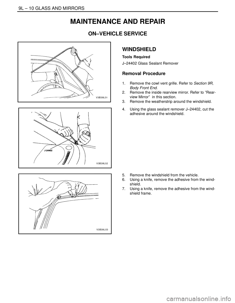
4. Using the glass sealant remover J–24402, cut the
adhesive around the windshield.
5. Remove the windshield from the vehicle.
6. Using a knife, remove the adhesive from the wind-
shield.
7. Using a knife, remove the adhesive from the wind-
shield frame.
Page 2390 of 2643
GLASS AND MIRRORS 9L – 11
DAEWOO V–121 BL4
Installation Procedure
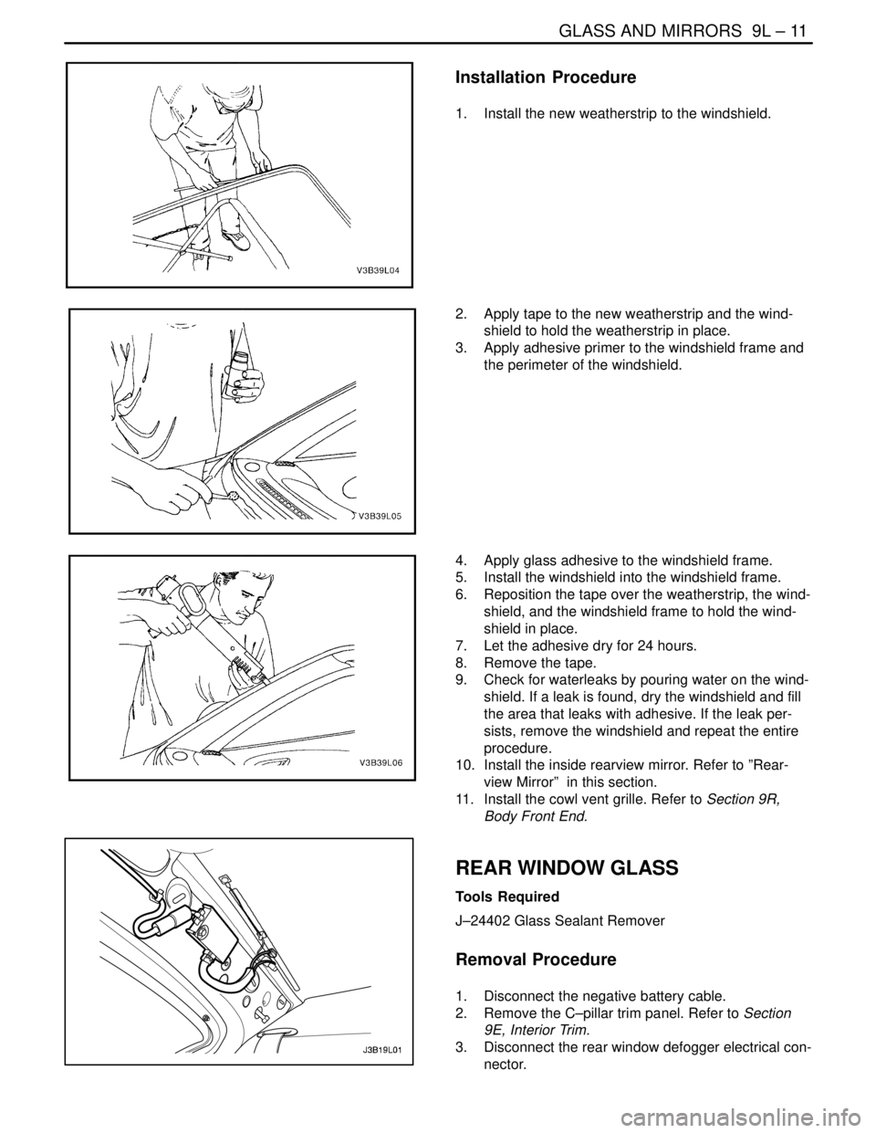
1. Install the new weatherstrip to the windshield.
2. Apply tape to the new weatherstrip and the wind-
shield to hold the weatherstrip in place.
3. Apply adhesive primer to the windshield frame and
the perimeter of the windshield.
4. Apply glass adhesive to the windshield frame.
5. Install the windshield into the windshield frame.
6. Reposition the tape over the weatherstrip, the wind-
shield, and the windshield frame to hold the wind-
shield in place.
7. Let the adhesive dry for 24 hours.
8. Remove the tape.
9. Check for waterleaks by pouring water on the wind-
shield. If a leak is found, dry the windshield and fill
the area that leaks with adhesive. If the leak per-
sists, remove the windshield and repeat the entire
procedure.
10. Install the inside rearview mirror. Refer to ”Rear-
view Mirror” in this section.
11. Install the cowl vent grille. Refer to Section 9R,
Body Front End.
REAR WINDOW GLASS
Tools Required
J–24402 Glass Sealant Remover
Removal Procedure
1. Disconnect the negative battery cable.
2. Remove the C–pillar trim panel. Refer to Section
9E, Interior Trim.
3. Disconnect the rear window defogger electrical con-
nector.
Page 2392 of 2643
GLASS AND MIRRORS 9L – 13
DAEWOO V–121 BL4
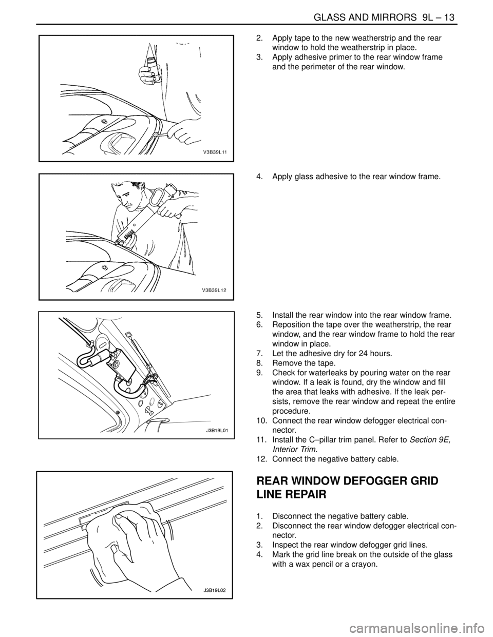
2. Apply tape to the new weatherstrip and the rear
window to hold the weatherstrip in place.
3. Apply adhesive primer to the rear window frame
and the perimeter of the rear window.
4. Apply glass adhesive to the rear window frame.
5. Install the rear window into the rear window frame.
6. Reposition the tape over the weatherstrip, the rear
window, and the rear window frame to hold the rear
window in place.
7. Let the adhesive dry for 24 hours.
8. Remove the tape.
9. Check for waterleaks by pouring water on the rear
window. If a leak is found, dry the window and fill
the area that leaks with adhesive. If the leak per-
sists, remove the rear window and repeat the entire
procedure.
10. Connect the rear window defogger electrical con-
nector.
11. Install the C–pillar trim panel. Refer to Section 9E,
Interior Trim.
12. Connect the negative battery cable.
REAR WINDOW DEFOGGER GRID
LINE REPAIR
1. Disconnect the negative battery cable.
2. Disconnect the rear window defogger electrical con-
nector.
3. Inspect the rear window defogger grid lines.
4. Mark the grid line break on the outside of the glass
with a wax pencil or a crayon.
Page 2394 of 2643
GLASS AND MIRRORS 9L – 15
DAEWOO V–121 BL4
REAR WINDOW DEFOGGER
BRAIDED LEAD WIRE REPAIR
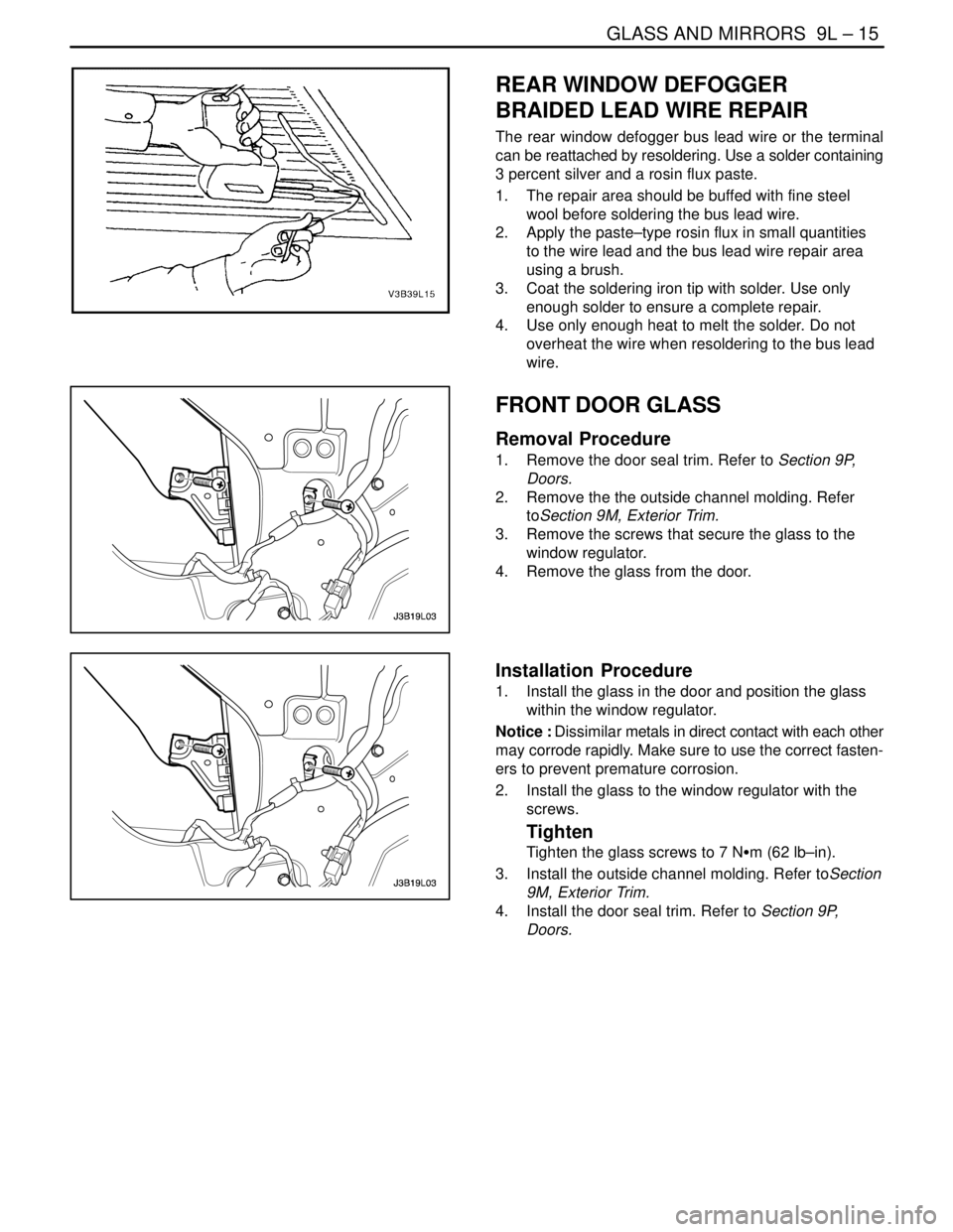
The rear window defogger bus lead wire or the terminal
can be reattached by resoldering. Use a solder containing
3 percent silver and a rosin flux paste.
1. The repair area should be buffed with fine steel
wool before soldering the bus lead wire.
2. Apply the paste–type rosin flux in small quantities
to the wire lead and the bus lead wire repair area
using a brush.
3. Coat the soldering iron tip with solder. Use only
enough solder to ensure a complete repair.
4. Use only enough heat to melt the solder. Do not
overheat the wire when resoldering to the bus lead
wire.
FRONT DOOR GLASS
Removal Procedure
1. Remove the door seal trim. Refer to Section 9P,
Doors.
2. Remove the the outside channel molding. Refer
toSection 9M, Exterior Trim.
3. Remove the screws that secure the glass to the
window regulator.
4. Remove the glass from the door.
Installation Procedure
1. Install the glass in the door and position the glass
within the window regulator.
Notice : Dissimilar metals in direct contact with each other
may corrode rapidly. Make sure to use the correct fasten-
ers to prevent premature corrosion.
2. Install the glass to the window regulator with the
screws.
Tighten
Tighten the glass screws to 7 NSm (62 lb–in).
3. Install the outside channel molding. Refer toSection
9M, Exterior Trim.
4. Install the door seal trim. Refer to Section 9P,
Doors.
Page 2395 of 2643
9L – 16IGLASS AND MIRRORS
DAEWOO V–121 BL4
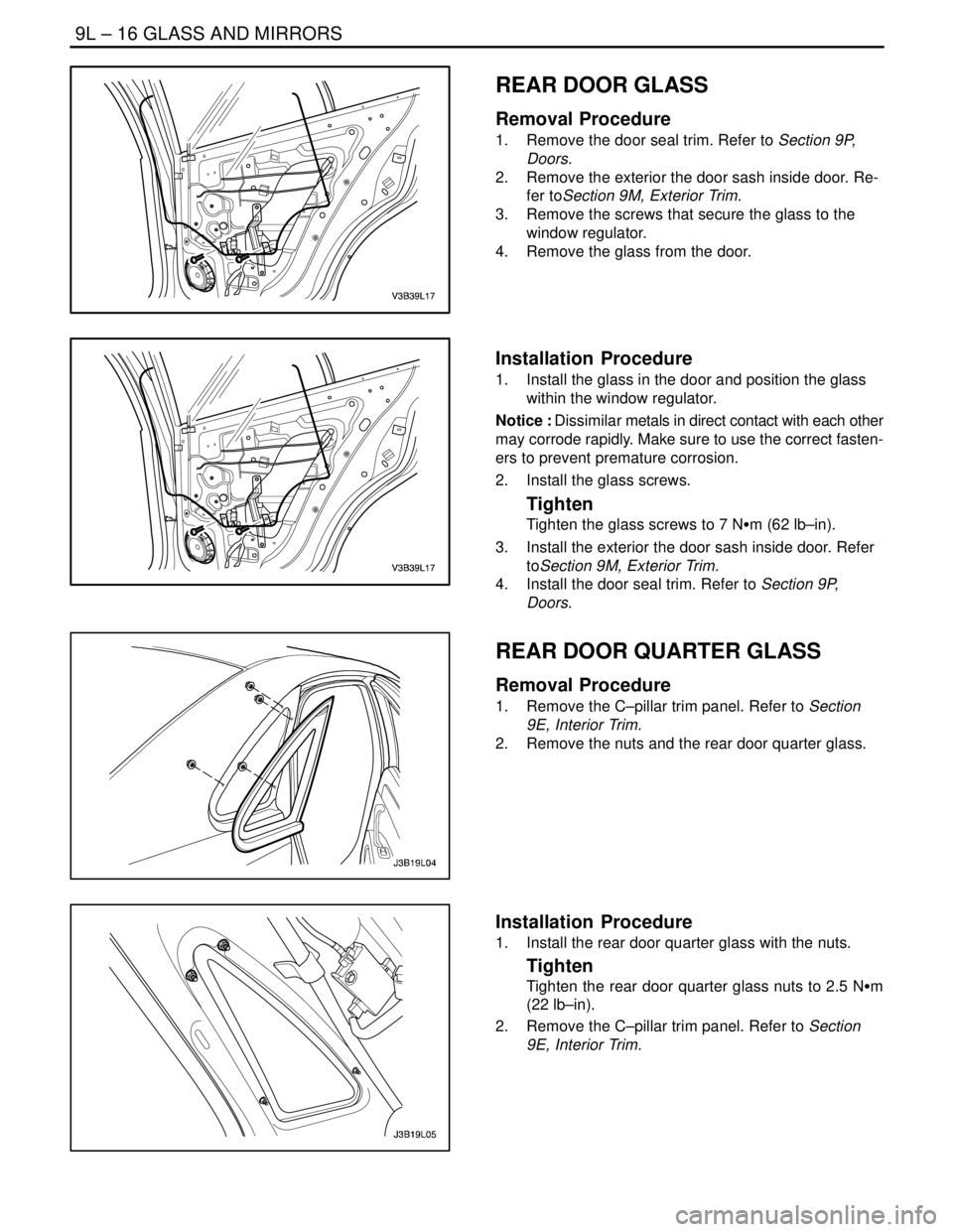
REAR DOOR GLASS
Removal Procedure
1. Remove the door seal trim. Refer to Section 9P,
Doors.
2. Remove the exterior the door sash inside door. Re-
fer toSection 9M, Exterior Trim.
3. Remove the screws that secure the glass to the
window regulator.
4. Remove the glass from the door.
Installation Procedure
1. Install the glass in the door and position the glass
within the window regulator.
Notice : Dissimilar metals in direct contact with each other
may corrode rapidly. Make sure to use the correct fasten-
ers to prevent premature corrosion.
2. Install the glass screws.
Tighten
Tighten the glass screws to 7 NSm (62 lb–in).
3. Install the exterior the door sash inside door. Refer
toSection 9M, Exterior Trim.
4. Install the door seal trim. Refer to Section 9P,
Doors.
REAR DOOR QUARTER GLASS
Removal Procedure
1. Remove the C–pillar trim panel. Refer to Section
9E, Interior Trim.
2. Remove the nuts and the rear door quarter glass.
Installation Procedure
1. Install the rear door quarter glass with the nuts.
Tighten
Tighten the rear door quarter glass nuts to 2.5 NSm
(22 lb–in).
2. Remove the C–pillar trim panel. Refer to Section
9E, Interior Trim.