2004 DAEWOO LACETTI Solenoid
[x] Cancel search: SolenoidPage 17 of 2643

0B – 10IGENERAL INFORMATION
DAEWOO V–121 BL4
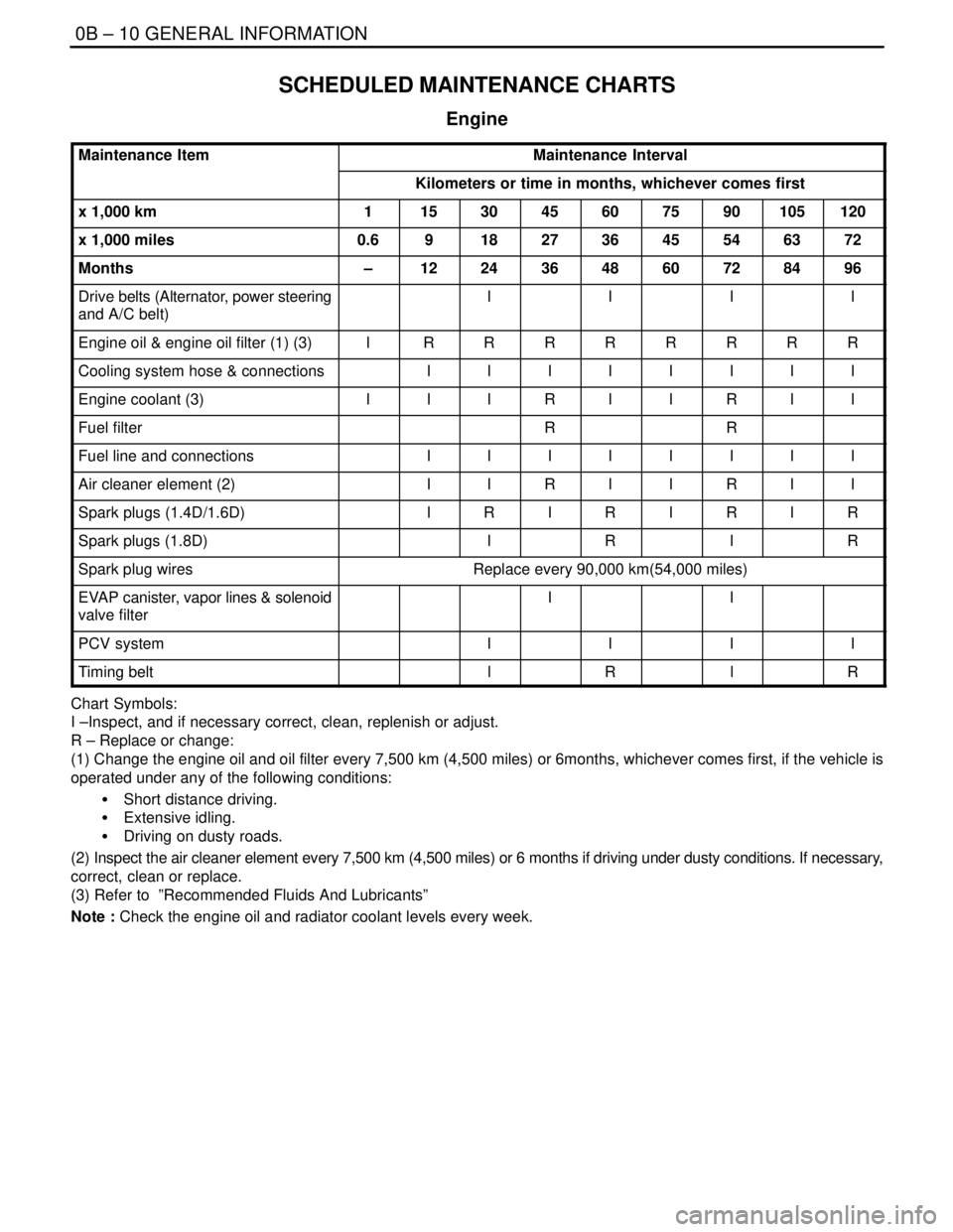
SCHEDULED MAINTENANCE CHARTS
Engine
Maintenance ItemMaintenance Interval
Kilometers or time in months, whichever comes first
x 1,000 km1153045607590105120
x 1,000 miles0.6918273645546372
Months–1224364860728496
Drive belts (Alternator, power steering
and A/C belt)IIII
Engine oil & engine oil filter (1) (3)IRRRRRRRR
Cooling system hose & connectionsIIIIIIII
Engine coolant (3)IIIRIIRII
Fuel filterRR
Fuel line and connectionsIIIIIIII
Air cleaner element (2)IIRIIRII
Spark plugs (1.4D/1.6D)IRIRIRIR
Spark plugs (1.8D)IRIR
Spark plug wiresReplace every 90,000 km(54,000 miles)
EVAP canister, vapor lines & solenoid
valve filterII
PCV systemIIII
Timing beltlRlR
Chart Symbols:
I –Inspect, and if necessary correct, clean, replenish or adjust.
R – Replace or change:
(1) Change the engine oil and oil filter every 7,500 km (4,500 miles) or 6months, whichever comes first, if the vehicle is
operated under any of the following conditions:
S Short distance driving.
S Extensive idling.
S Driving on dusty roads.
(2) Inspect the air cleaner element every 7,500 km (4,500 miles) or 6 months if driving under dusty conditions. If necessary,
correct, clean or replace.
(3) Refer to ”Recommended Fluids And Lubricants”
Note : Check the engine oil and radiator coolant levels every week.
Page 92 of 2643

1.4L/1.6L DOHC ENGINE MECHANICAL 1C1 – 49
DAEWOO V–121 BL4
17. Disconnect the oxygen (O2) sensor connector, if
equipped.
18. Disconnect the fuel injector harness connectors.
19. Disconnect the MAT, MAP sensor connectors.
20. Disconnect the throttle position sensor (TPS) con-
nector.
21. Disconnect the generator voltage regulator connec-
tor and power lead.
22. Remove the electrical harness clamp bolt.
23. Disconnect all of the necessary vacuum lines, in-
cluding the brake booster vacuum hose.
24. Disconnect the fuel feed line at the fuel rail.
25. Disconnect the throttle cable from the throttle body
and the intake manifold bracket.
26. Disconnect the surge tank coolant hose at the
throttle body.
27. Disconnect the heater outlet hose at the coolant
pipe.
28. Disconnect the heater inlet hose from the cylinder
head.
29. Disconnect the surge tank coolant hose from the
coolant pipe.
30. Disconnect the lower radiator hose from the coolant
pipe. Disconnect the starter solenoid ”S” terminal
wire. Remove the A/C compressor, if equipped. Re-
fer to Section 7B, Manual Control Heating, Ventila-
tion, and Air Conditioning Systems.
31. Remove the catalytic converter retaining nuts from
the exhaust pipe.
32. Remove the exhaust pipe.
Page 93 of 2643

1C1 – 50I1.4L/1.6L DOHC ENGINE MECHANICAL
DAEWOO V–121 BL4
33. Remove the crankshaft pulley bolt.
34. Remove the crankshaft pulley.
35. Disconnect the vacuum lines at the charcoal canis-
ter purge solenoid.
36. Disconnect the electrical connector at the charcoal
canister purge (CCP) solenoid and at the knock
sensor.
37. Disconnect the electrical connector at the oil pres-
sure switch and at the exhaust gas recirculation
(EGR) solenoid.
38. Disconnect the crankshaft position sensor (CPS)
connector.
39. Remove the transaxle torque converter bolts, if au-
tomatic transaxle equipped.
40. Remove the stater motor. Refer to Section 1E, En-
gine Electrical.
41. Remove the transaxle bell housing bolts.
42. Support the transaxle with a floor jack.
43. Install the engine lifting device.
44. Disconnect the right engine mount bracket from the
engine mount and the engine by removing the at-
taching bolts and the nuts.
45. Remove the right engine mount from the engine
block. Refer to ”Engine Mount” in this section.
46. Separate the engine block from the transaxle.
47. Remove the engine.
Installation Procedure
1. Install the engine into the engine compartment.
2. Align the engine alignment pins to the transaxle.
3. Install the transaxle bell housing bolts.
Tighten
Tighten the transaxle bell housing bolts to 75 NSm (55
lb–ft).
4. Install the right engine mount to the engine block.
Refer to ”Engine Mount” in this section.
Page 94 of 2643

1.4L/1.6L DOHC ENGINE MECHANICAL 1C1 – 51
DAEWOO V–121 BL4
5. Connect the right engine mount bracket to the en-
gine mount and the engine by installing the attach-
ing bolts and the nuts.
Tighten
Tighten the engine mount bracket attaching bolts and
the nuts to 55 NSm (41 lb–ft).
6. Remove the floor jack used for support of the trans-
axle.
7. Remove the engine lifting device.
8. Install the transaxle torque converter bolts, if auto-
matic transaxle equipped.
Tighten
Tighten the transaxle torque converter bolts to 45
NSm (33 lb–ft).
9. Install the starter motor. Refer to Section 1E, En-
gine Electrical.
10. Connect the vacuum lines at the CCP solenoid.
11. Connect the electrical connector at the CCP sole-
noid and at the knock sensor.
12. Connect the oil pressure switch and the EGR sole-
noid connectors.
13. Install the crankshaft pulley.
14. Install the crankshaft pulley bolt.
Tighten
Tighten the crankshaft pulley bolt to 95 NSm (70 lb–ft)
and retighten 30 degrees plus 15 degrees.
15. Connect the CPS connector.
16. Install the exhaust front pipe.
17. Install the catalytic converter retaining nuts to the
exhaust pipe.
Tighten
Tighten the catalytic converter to exhaust pipe retain-
ing nuts to 35 NSm (26 lb–ft).
Page 95 of 2643

1C1 – 52I1.4L/1.6L DOHC ENGINE MECHANICAL
DAEWOO V–121 BL4
18. Connect the power steering pressure hose.
19. Connect the power steering return hose.
20. Install the A/C compressor, if equipped. Refer to
Section 7B, Manual Control Heating, Ventilation,
and Air Conditioning Systems.
21. Install the generator. Refer to Section 1E, Engine
Electrical.
22. Install the serpentine accessory drive belt. Refer to
Section 6B, Power Steering Pump.
23. Install the right front wheel well splash shield.
24. Install the right front wheel. Refer to Section 2E,
Tires and Wheels.
25. Connect the fuel feed line to the fuel rail.
26. Connect all of the necessary vacuum lines, includ-
ing the brake booster vacuum hose.
27. Connect the O2 sensor connector, if equipped.
28. Connect the starter solenoid ”S” terminal wire and
power lead.
29. Connect the generator voltage regulator connector
and power lead.
30. Connect the CTS connector.
31. Connect the MAP, MAT sensor connectors.
32. Connect the TPS connector.
33. Install the electrical wiring harness clamp at the
intake manifold support bracket.
34. Connect the fuel injector harness connectors.
35. Connect the electrical connector at the DIS coil and
the ECM ground terminal at the starter.
36. Install the air cleaner outlet hose between the
throttle body and the air cleaner housing.
37. Connect the breather tubes to the camshaft cover.
38. Install the cooling system radiator and the engine
cooling fans. Refer to Section 1D, Engine Cooling.
Page 129 of 2643

1.8L DOHC ENGINE MECHANICAL 1C2 – 9
DAEWOO V–121 BL4
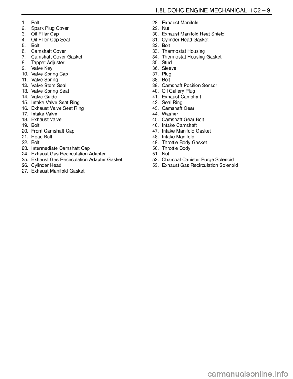
1. Bolt
2. Spark Plug Cover
3. Oil Filler Cap
4. Oil Filler Cap Seal
5. Bolt
6. Camshaft Cover
7. Camshaft Cover Gasket
8. Tappet Adjuster
9. Valve Key
10. Valve Spring Cap
11. Valve Spring
12. Valve Stem Seal
13. Valve Spring Seat
14. Valve Guide
15. Intake Valve Seat Ring
16. Exhaust Valve Seat Ring
17. Intake Valve
18. Exhaust Valve
19. Bolt
20. Front Camshaft Cap
21. Head Bolt
22. Bolt
23. Intermediate Camshaft Cap
24. Exhaust Gas Recirculation Adapter
25. Exhaust Gas Recirculation Adapter Gasket
26. Cylinder Head
27. Exhaust Manifold Gasket28. Exhaust Manifold
29. Nut
30. Exhaust Manifold Heat Shield
31. Cylinder Head Gasket
32. Bolt
33. Thermostat Housing
34. Thermostat Housing Gasket
35. Stud
36. Sleeve
37. Plug
38. Bolt
39. Camshaft Position Sensor
40. Oil Gallery Plug
41. Exhaust Camshaft
42. Seal Ring
43. Camshaft Gear
44. Washer
45. Camshaft Gear Bolt
46. Intake Camshaft
47. Intake Manifold Gasket
48. Intake Manifold
49. Throttle Body Gasket
50. Throttle Body
51. Nut
52. Charcoal Canister Purge Solenoid
53. Exhaust Gas Recirculation Solenoid
Page 137 of 2643

1.8L DOHC ENGINE MECHANICAL 1C2 – 17
DAEWOO V–121 BL4
53. Remove the generator–to–intake manifold support
bracket bolts at the cylinder head and the intake
manifold.
54. Remove the generator support bracket.
55. Remove the intake manifold–to–generator strap
bracket bolt and loosen the bolt on the generator.
56. Move the strap clear of the intake manifold.
57. Remove the charcoal canister purge (CCP) and
EGR solenoid bracket bolt and move the bracket
clear.
58. Disconnect the throttle cable at the throttle body
and the intake manifold.
59. Loosen all of the cylinder head bolts gradually and
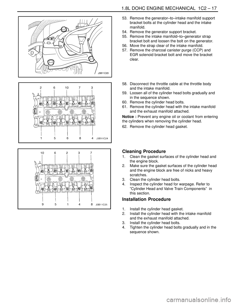
in the sequence shown.
60. Remove the cylinder head bolts.
61. Remove the cylinder head with the intake manifold
and the exhaust manifold attached.
Notice : Prevent any engine oil or coolant from entering
the cylinders when removing the cylinder head.
62. Remove the cylinder head gasket.
Cleaning Procedure
1. Clean the gasket surfaces of the cylinder head and
the engine block.
2. Make sure the gasket surfaces of the cylinder head
and the engine block are free of nicks and heavy
scratches.
3. Clean the cylinder head bolts.
4. Inspect the cylinder head for warpage. Refer to
”Cylinder Head and Valve Train Components” in
this section.
Installation Procedure
1. Install the cylinder head gasket.
2. Install the cylinder head with the intake manifold
and the exhaust manifold attached.
3. Install the cylinder head bolts.
4. Tighten the cylinder head bolts gradually and in the
sequence shown.
Page 142 of 2643

1C2 – 22I1.8L DOHC ENGINE MECHANICAL
DAEWOO V–121 BL4
56. Connect the CTS connector.
57. Connect the engine CTS connector.
58. Connect the IAC valve connector.
59. Connect the TPS connector.
60. Install the CCP and the EGR solenoid bracket bolt.
Tighten
Tighten the charcoal canister purge and exhaust gas
recirculation solenoid bracket bolt to 5 NSm (44 lb–in).
61. Connect the DIS coil connector.
62. Connect the O2 sensor connector, if equipped.
63. Connect the ECM ground terminal.
64. Install the fuel pump fuse.
65. Connect the negative battery ground cable.
66. Refill the engine cooling system. Refer to Section
1D, Engine Cooling.
CAMSHAFTS
Removal Procedure
1. Remove the timing belt. Refer to ”Timing Belt” in
this section.
2. Disconnect the breather tube at the camshaft cov-
er.
3. Disconnect the engine ventilation hose at the cam-
shaft cover.
4. Remove the spark plug cover bolts.
5. Remove the spark plug cover.
6. Disconnect the ignition wires from the spark plugs.
7. Remove the camshaft cover bolts.
8. Remove the camshaft cover washers.
9. Remove the camshaft cover and the camshaft cov-
er gasket.
Notice : Take extreme care to prevent any scratches,
nicks or damage to the camshafts.
10. While holding the intake camshaft firmly in place,
remove the intake camshaft gear bolt.
11. Remove the intake camshaft gear.
12. While holding the exhaust camshaft firmly in place,
remove the exhaust camshaft gear bolt.
13. Remove the exhaust camshaft gear.