Page 96 of 2643

1.4L/1.6L DOHC ENGINE MECHANICAL 1C1 – 53
DAEWOO V–121 BL4
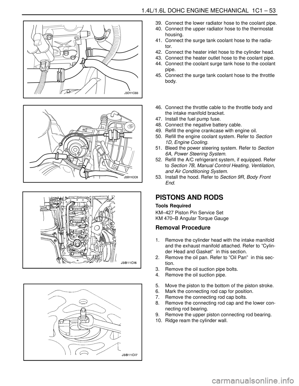
39. Connect the lower radiator hose to the coolant pipe.
40. Connect the upper radiator hose to the thermostat
housing.
41. Connect the surge tank coolant hose to the radia-
tor.
42. Connect the heater inlet hose to the cylinder head.
43. Connect the heater outlet hose to the coolant pipe.
44. Connect the coolant surge tank hose to the coolant
pipe.
45. Connect the surge tank coolant hose to the throttle
body.
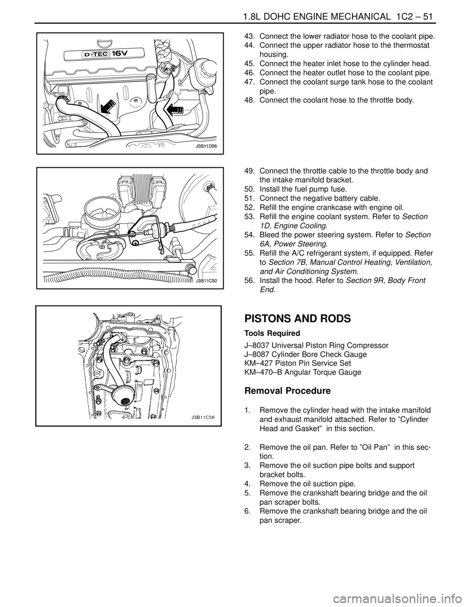
46. Connect the throttle cable to the throttle body and
the intake manifold bracket.
47. Install the fuel pump fuse.
48. Connect the negative battery cable.
49. Refill the engine crankcase with engine oil.
50. Refill the engine coolant system. Refer to Section
1D, Engine Cooling.
51. Bleed the power steering system. Refer to Section
6A, Power Steering System.
52. Refill the A/C refrigerant system, if equipped. Refer
to Section 7B, Manual Control Heating, Ventilation,
and Air Conditioning System.
53. Install the hood. Refer to Section 9R, Body Front
End.
PISTONS AND RODS
Tools Required
KM–427 Piston Pin Service Set
KM 470–B Angular Torque Gauge
Removal Procedure
1. Remove the cylinder head with the intake manifold
and the exhaust manifold attached. Refer to ”Cylin-
der Head and Gasket” in this section.
2. Remove the oil pan. Refer to ”Oil Pan” in this sec-
tion.
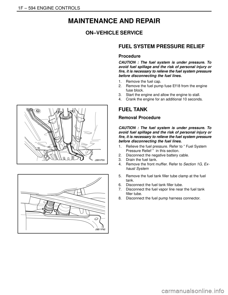
3. Remove the oil suction pipe bolts.
4. Remove the oil suction pipe.
5. Move the piston to the bottom of the piston stroke.
6. Mark the connecting rod cap for position.
7. Remove the connecting rod cap bolts.
8. Remove the connecting rod cap and the lower con-
necting rod bearing.
9. Remove the upper piston connecting rod bearing.
10. Ridge ream the cylinder wall.
Page 171 of 2643

1.8L DOHC ENGINE MECHANICAL 1C2 – 51
DAEWOO V–121 BL4
43. Connect the lower radiator hose to the coolant pipe.
44. Connect the upper radiator hose to the thermostat
housing.
45. Connect the heater inlet hose to the cylinder head.
46. Connect the heater outlet hose to the coolant pipe.
47. Connect the coolant surge tank hose to the coolant
pipe.
48. Connect the coolant hose to the throttle body.
49. Connect the throttle cable to the throttle body and
the intake manifold bracket.
50. Install the fuel pump fuse.
51. Connect the negative battery cable.
52. Refill the engine crankcase with engine oil.
53. Refill the engine coolant system. Refer to Section
1D, Engine Cooling.
54. Bleed the power steering system. Refer to Section
6A, Power Steering.
55. Refill the A/C refrigerant system, if equipped. Refer
to Section 7B, Manual Control Heating, Ventilation,
and Air Conditioning System.
56. Install the hood. Refer to Section 9R, Body Front
End.
PISTONS AND RODS
Tools Required
J–8037 Universal Piston Ring Compressor
J–8087 Cylinder Bore Check Gauge
KM–427 Piston Pin Service Set
KM–470–B Angular Torque Gauge
Removal Procedure
1. Remove the cylinder head with the intake manifold
and exhaust manifold attached. Refer to ”Cylinder
Head and Gasket” in this section.
2. Remove the oil pan. Refer to ”Oil Pan” in this sec-
tion.
3. Remove the oil suction pipe bolts and support
bracket bolts.
4. Remove the oil suction pipe.
5. Remove the crankshaft bearing bridge and the oil
pan scraper bolts.
6. Remove the crankshaft bearing bridge and the oil
pan scraper.
Page 840 of 2643

1F – 594IENGINE CONTROLS
DAEWOO V–121 BL4
MAINTENANCE AND REPAIR
ON–VEHICLE SERVICE
FUEL SYSTEM PRESSURE RELIEF
Procedure
CAUTION : The fuel system is under pressure. To
avoid fuel spillage and the risk of personal injury or
fire, it is necessary to relieve the fuel system pressure
before disconnecting the fuel lines.
1. Remove the fuel cap.
2. Remove the fuel pump fuse Ef18 from the engine
fuse block.
3. Start the engine and allow the engine to stall.
4. Crank the engine for an additional 10 seconds.
FUEL TANK
Removal Procedure
CAUTION : The fuel system is under pressure. To
avoid fuel spillage and the risk of personal injury or
fire, it is necessary to relieve the fuel system pressure
before disconnecting the fuel lines.
1. Relieve the fuel pressure. Refer to ” Fuel System
Pressure Relief ” in this section.
2. Disconnect the negative battery cable.
3. Drain the fuel tank.
4. Remove the front muffler. Refer to Section 1G, Ex-
haust System
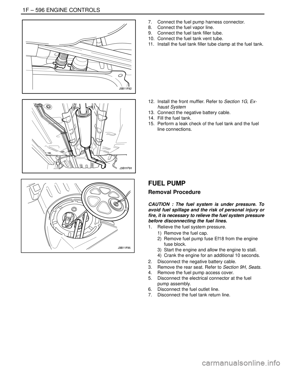
5. Remove the fuel tank filler tube clamp at the fuel
tank.
6. Disconnect the fuel tank filler tube.
7. Disconnect the fuel vapor line near the fuel tank
filler tube.
8. Disconnect the fuel pump harness connector.
Page 842 of 2643

1F – 596IENGINE CONTROLS
DAEWOO V–121 BL4
7. Connect the fuel pump harness connector.
8. Connect the fuel vapor line.
9. Connect the fuel tank filler tube.
10. Connect the fuel tank vent tube.
11. Install the fuel tank filler tube clamp at the fuel tank.
12. Install the front muffler. Refer to Section 1G, Ex-
haust System
13. Connect the negative battery cable.
14. Fill the fuel tank.
15. Perform a leak check of the fuel tank and the fuel
line connections.
FUEL PUMP
Removal Procedure
CAUTION : The fuel system is under pressure. To
avoid fuel spillage and the risk of personal injury or
fire, it is necessary to relieve the fuel system pressure
before disconnecting the fuel lines.
1. Relieve the fuel system pressure.
1) Remove the fuel cap.
2) Remove fuel pump fuse Ef18 from the engine
fuse block.
3) Start the engine and allow the engine to stall.
4) Crank the engine for an additional 10 seconds.
2. Disconnect the negative battery cable.
3. Remove the rear seat. Refer to Section 9H, Seats.
4. Remove the fuel pump access cover.
5. Disconnect the electrical connector at the fuel
pump assembly.
6. Disconnect the fuel outlet line.
7. Disconnect the fuel tank return line.
Page 843 of 2643

ENGINE CONTROLS 1F – 597
DAEWOO V–121 BL4
8. Turn the lock ring counterclockwise to clear the
tank tabs.
9. Remove the fuel pump assembly from the tank.
Installation Procedure
1. Clean the gasket mating surface on the fuel tank.
2. Position the new gasket in place.
3. Install the fuel pump into the fuel tank in the same
location as removed for ease of line and connector
installation.
4. Position the lock ring in place and turn it clockwise
until it contacts the tank stop.
5. Connect the fuel pump assembly connector.
6. Install the fuel pump outlet line.
7. Install the fuel tank return line.
8. Install the fuel pump access cover.
9. Connect the negative battery cable.
10. Perform an operational check of the fuel pump.
11. Install the rear seat. Refer to Section 9H, Seats.
FUEL FILTER
Removal Procedure
CAUTION : The fuel system is under pressure. To
avoid fuel spillage and the risk of personal injury or
fire, it is necessary to relieve the fuel system pressure
before disconnecting the fuel lines.
1. Relieve the fuel system pressure. Refer to ” Fuel
System Pressure Relief ” in this section.
2. Disconnect the negative battery cable.
3. Remove the fuel filter mounting bracket assembly
bolt.
4. Remove the fuel filter cover.
5. Disconnect the inlet/outlet fuel lines by moving the
line connector lock forward and pulling the hose off
of the fuel filter tube.