2004 DAEWOO LACETTI Solenoid
[x] Cancel search: SolenoidPage 237 of 2643
ENGINE ELECTRICAL 1E – 23
DAEWOO V–121 BL4
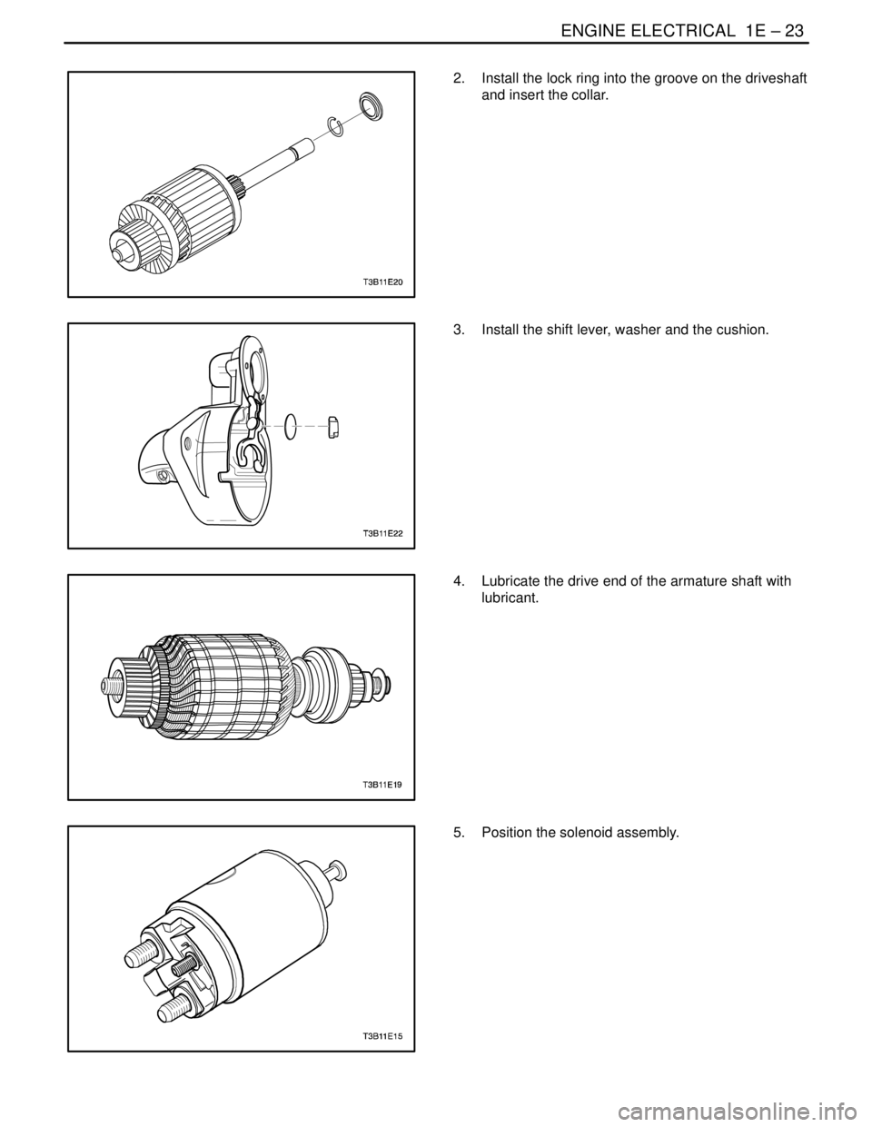
2. Install the lock ring into the groove on the driveshaft
and insert the collar.
3. Install the shift lever, washer and the cushion.
4. Lubricate the drive end of the armature shaft with
lubricant.
5. Position the solenoid assembly.
Page 238 of 2643
1E – 24IENGINE ELECTRICAL
DAEWOO V–121 BL4
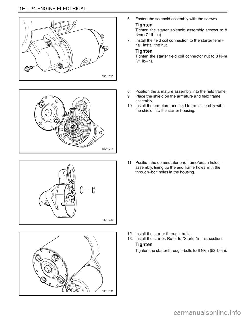
6. Fasten the solenoid assembly with the screws.
Tighten
Tighten the starter solenoid assembly screws to 8
NSm (71 lb–in).
7. Install the field coil connection to the starter termi-
nal. Install the nut.
Tighten
Tighten the starter field coil connector nut to 8 NSm
(71 lb–in).
8. Position the armature assembly into the field frame.
9. Place the shield on the armature and field frame
assembly.
10. Install the armature and field frame assembly with
the shield into the starter housing.
11. Position the commutator end frame/brush holder
assembly, lining up the end frame holes with the
through–bolt holes in the housing.
12. Install the starter through–bolts.
13. Install the starter. Refer to ”Starter”in this section.
Tighten
Tighten the starter through–bolts to 6 NSm (53 lb–in).
Page 246 of 2643
1E – 32IENGINE ELECTRICAL
DAEWOO V–121 BL4
the same cable to the positive terminal on the other
battery. Never connect the other end to the nega-
tive terminal of the discharged battery.
CAUTION : To avoid injury do not attach the cable di-
rectly to the negative terminal of the discharged bat-
tery. Doing so could cause sparks and a possible bat-
tery explosion.
6. Clamp one end of the second cable to the negative
terminal of the booster battery. Make the final con-
nection to a solid engine ground (such as the en-
gine lift bracket) at least 450 millimeters (18 inches)
from the discharged battery.
7. Start the engine of the vehicle with the good bat-
tery. Run the engine at a moderate speed for sever-
al minutes. Then start the engine of the vehicle
which has the discharged battery.
8. Remove the jumper cables by reversing the above
sequence exactly. Remove the negative cable from
the vehicle with the discharged battery first. While
removing each clamp, take care that it does not
touch any other metal while the other end remains
attached.
GENERATOR
The Delco–Remy CS charging system has several mod-
els available, including the CS. The number denotes the
outer diameter in millimeters of the stator lamination.
CS generators are equipped with internal regulators. A
Delta stator, a rectifier bridge, and a rotor with slip rings
and brushes are electrically similar to earlier generators.
A conventional pulley and fan are used. There is no test
hole.
Unlike three–wire generators, the CS may be used with
only two connections: battery positive and an ”L’’ terminal
to the charge indicator lamp.
As with other charging systems, the charge indicator lamp
lights when the ignition switch is turned to RUN, and goes
out when the engine is running. If the charge indicator is
on with the engine running, a charging system defect is in-
dicated. This indicator light will glow at full brilliance for
several kinds of defects as well as when the system volt-
age is too high or too low.The regulator voltage setting varies with temperature and
limits the system voltage by controlling rotor field current.
At high speeds, the on–time may be 10 percent and the
off–time 90 percent. At low speeds, with high electrical
loads, on–time may be 90 percent and the off–time 10 per-
cent.
CHARGING SYSTEM
CS generators use a new type of regulator that incorpo-
rates a diode trio. A Delta stator, a rectifier bridge, and a
rotor with slip rings and brushes are electrically similar to
earlier generators. A conventional pulley and fan are used.
There is no test hole.
STARTER
Wound field starter motors have pole pieces, arranged
around the armature, which are energized by wound field
coils.
Enclosed shift lever cranking motors have the shift lever
mechanism and the solenoid plunger enclosed in the drive
housing, protecting them from exposure to dirt, icy condi-
tions, and splashes.
In the basic circuit, solenoid windings are energized when
the switch is closed. The resulting plunger and shift lever
movement causes the pinion to engage the engine fly-
wheel ring gear. The solenoid main contacts close. Crank-
ing then takes place.
When the engine starts, pinion overrun protects the arma-
ture from excessive speed until the switch is opened, at
which time the return spring causes the pinion to disen-
gage. To prevent excessive overrun, the switch should be
released immediately after the engine starts.
STARTING SYSTEM
The engine electrical system includes the battery, the igni-
tion, the starter, the generator, and all the related wiring.
Diagnostic tables will aid in troubleshooting system faults.
When a fault is traced to a particular component, refer to
that component section of the service manual.
The starting system circuit consists of the battery, the
starter motor, the ignition switch, and all the related electri-
cal wiring. All of these components are connected electri-
cally.
Page 249 of 2643

ENGINE CONTROLS 1F – 3
DAEWOO V–121 BL4
DTC P0562 System Voltage(Engine Side) Too
Low 1F–270. . . . . . . . . . . . . . . . . . . . . . . . . . . . . . . . . .
DTC P0563 System Voltage(Engine Side) Too
High 1F–272. . . . . . . . . . . . . . . . . . . . . . . . . . . . . . . . . .
DTC P0601 Engine Control Module Checksum
Error 1F–274. . . . . . . . . . . . . . . . . . . . . . . . . . . . . . . . .
DTC P0604 Engine Control Module Internal/External
RAM Error 1F–275. . . . . . . . . . . . . . . . . . . . . . . . . . . .
DTC P0605 Engine Control Module INMVY Write
Error 1F–276. . . . . . . . . . . . . . . . . . . . . . . . . . . . . . . . .
DTC P0656 Fuel Level Gauge Circuit Fault 1F–277. .
DTC P1181 Variable Intake Manifold Solenoid
Low Voltage 1F–279. . . . . . . . . . . . . . . . . . . . . . . . . . .
DTC P1182 Variable Intake Manifold Solenoid
High Voltage 1F–281. . . . . . . . . . . . . . . . . . . . . . . . . .
DTC P1230 Fuel Pump Relay Low Voltage
(1.4L DOHC) 1F–283. . . . . . . . . . . . . . . . . . . . . . . . . .
DTC P1230 Fuel Pump Relay Low Voltage
(1.6L DOHC) 1F–286. . . . . . . . . . . . . . . . . . . . . . . . . .
DTC P1231 Fuel Pump Relay High Voltage
(1.4L DOHC) 1F–289. . . . . . . . . . . . . . . . . . . . . . . . . .
DTC P1231 Fuel Pump Relay High Voltage
(1.6L DOHC) 1F–292. . . . . . . . . . . . . . . . . . . . . . . . . .
DTC P1320 Crankshaft Segment Period
Segment Adaptation At Limit 1F–295. . . . . . . . . . . .
DTC P1321 Crankshaft Segment Period Tooth
Error 1F–297. . . . . . . . . . . . . . . . . . . . . . . . . . . . . . . . .
DTC P1382 Rough Road Data Invalid
(NON ABS) 1F–299. . . . . . . . . . . . . . . . . . . . . . . . . . .
DTC P1382 Rough Road Data Invalid (ABS) 1F–302
DTC P1385 Rough Road Sensor Circuit Fault
(NON ABS) 1F–305. . . . . . . . . . . . . . . . . . . . . . . . . . .
DTC P1402 Exhaust Gas Recirculation
Blocked 1F–308. . . . . . . . . . . . . . . . . . . . . . . . . . . . . . .
DTC P1403 Exhaust Gas Recirculation Valve
Failure 1F–310. . . . . . . . . . . . . . . . . . . . . . . . . . . . . . . .
DTC P1404 Exhaust Gas Recirculation Closed1F–313
DTC P1511 Idle Charge Actuator Circuit Fault 1F–316
DTC P1512 Idle Charge Actuator Mechanical
Error 1F–319. . . . . . . . . . . . . . . . . . . . . . . . . . . . . . . . .
DTC P1513 Idle Charge Actuator Functional
Error 1F–321. . . . . . . . . . . . . . . . . . . . . . . . . . . . . . . . .
DTC P1537 A/C Compressor Relay High
Voltage 1F–324. . . . . . . . . . . . . . . . . . . . . . . . . . . . . . .
DTC P1538 A/C Compressor Relay Low
Voltage 1F–326. . . . . . . . . . . . . . . . . . . . . . . . . . . . . . .
DTC P1610 Main Relay High Voltage
(1.4L DOCH) 1F–328. . . . . . . . . . . . . . . . . . . . . . . . . .
DTC P1610 Main Relay High Voltage
(1.6L DOHC) 1F–330. . . . . . . . . . . . . . . . . . . . . . . . . .
DTC P1611 Main Relay Low Voltage
(1.4L DOHC) 1F–332. . . . . . . . . . . . . . . . . . . . . . . . . . DTC P1611 Main Relay Low Voltage
(1.6L DOHC) 1F–334. . . . . . . . . . . . . . . . . . . . . . . . . .
DTC P1628 Immobilizer No Successful
Communication 1F–336. . . . . . . . . . . . . . . . . . . . . . . .
DTC P1629 Immobilizer Wrong Computation 1F–338
DTC P1660 Malfunction Indicator Lamp (MIL)
High Voltage 1F–340. . . . . . . . . . . . . . . . . . . . . . . . . .
DTC P1661 Malfunction Indicator Lamp (MIL)
Low Voltage 1F–342. . . . . . . . . . . . . . . . . . . . . . . . . . .
TROUBLE CODE DIAGNOSIS (1.8L DOHC) 1F–344.
Clearing Trouble Codes 1F–344. . . . . . . . . . . . . . . . . . .
Diagnostic Trouble Codes (1.8L DOHC) 1F–344. . . .
DTC P0106 Manifold Absolute Pressure
Rationality 1F–347. . . . . . . . . . . . . . . . . . . . . . . . . . . .
DTC P0107 Manifold Absolut Pressure Low
Voltage 1F–349. . . . . . . . . . . . . . . . . . . . . . . . . . . . . . .
DTC P0108 Manifold Absolut Pressure High
Voltage 1F–352. . . . . . . . . . . . . . . . . . . . . . . . . . . . . . .
DTC P0112 Intake Air Temperature Low
Voltage 1F–355. . . . . . . . . . . . . . . . . . . . . . . . . . . . . . .
DTC P0113 Intake Air Temperature High
Voltage 1F–358. . . . . . . . . . . . . . . . . . . . . . . . . . . . . . .
DTC P0117 Engine Coolant Temperature Low
Voltage 1F–361. . . . . . . . . . . . . . . . . . . . . . . . . . . . . . .
DTC P0118 Engine Coolant Temperature High
Voltage 1F–363. . . . . . . . . . . . . . . . . . . . . . . . . . . . . . .
DTC P0122 Throttle Position Sensor Low
Voltage 1F–366. . . . . . . . . . . . . . . . . . . . . . . . . . . . . . .
DTC P0123 Throttle Position Sensor High
Voltage 1F–369. . . . . . . . . . . . . . . . . . . . . . . . . . . . . . .
DTC P0131 Front Heated Oxygen Sensor
(HO2S1) Low Voltage 1F–372. . . . . . . . . . . . . . . . . .
DTC P0132 Front Heated Oxygen Sensor
(HO2S1) High Voltage 1F–375. . . . . . . . . . . . . . . . . .
DTC P0133 Front Heated Oxygen Sensor
(HO2S1) Slow Response 1F–378. . . . . . . . . . . . . . .
DTC P0134 Front Heated Oxygen Sensor
(HO2S1) No Activity or Open 1F–382. . . . . . . . . . . .
DTC P0135 Front Heated Oxygen Sensor
(HO2S1) Heater Circuit Not Functioning 1F–385. . .
DTC P0137 Rear Heated Oxygen Sensor
(HO2S2) Low Voltage 1F–388. . . . . . . . . . . . . . . . . .
DTC P0138 Rear Heated Oxygen Sensor
(HO2S2) High Voltage 1F–391. . . . . . . . . . . . . . . . . .
DTC P0140 Rear Heated Oxygen Sensor
(HO2S2) No Activity or Open 1F–394. . . . . . . . . . . .
DTC P0141 Rear Heated Oxygen Sensor
(HO2S2) Heater Circuit Not Functioning 1F–397. . .
DTC P0171 Fuel Trim System Too Lean 1F–400. . . .
DTC P0172 Fuel Trim System Too Rich 1F–404. . . . .
DTC P0201 Injector 1 Circuit Fault 1F–408. . . . . . . . .
DTC P0202 Injector 2 Circuit Fault 1F–411. . . . . . . . .
Page 250 of 2643

1F – 4IENGINE CONTROLS
DAEWOO V–121 BL4
DTC P0203 Injector 3 Circuit Fault 1F–414. . . . . . . . .
DTC P0204 Injector 4 Circuit Fault 1F–417. . . . . . . . .
DTC P0300 Multiple Cylinder Misfire Detected 1F–421
DTC P0301 Cylinder 1 Misfire 1F–426. . . . . . . . . . . . .
DTC P0302 Cylinder 2 Misfire 1F–431. . . . . . . . . . . . .
DTC P0303 Cylinder 3 Misfire 1F–436. . . . . . . . . . . . .
DTC P0304 Cylinder 4 Misfire 1F–441. . . . . . . . . . . . .
DTC P0317 Rough Road Sensor Source Not
Detected 1F–445. . . . . . . . . . . . . . . . . . . . . . . . . . . . . .
DTC P0325 Knock Sensor Internal
Malfunction 1F–447. . . . . . . . . . . . . . . . . . . . . . . . . . .
DTC P0327 Knock Sensor Circuit Fault 1F–449. . . . .
DTC P0336 58X Crank Position Extra/Missing
Pulses 1F–452. . . . . . . . . . . . . . . . . . . . . . . . . . . . . . . .
DTC P0337 58X Crank Position Sensor No
Signal 1F–455. . . . . . . . . . . . . . . . . . . . . . . . . . . . . . . .
DTC P0341 Camshaft Position Sensor
Rationality 1F–458. . . . . . . . . . . . . . . . . . . . . . . . . . . .
DTC P0342 Camshaft Position Sensor No
Signal 1F–461. . . . . . . . . . . . . . . . . . . . . . . . . . . . . . . .
DTC P0351 Ignition Control Circuit A Fault
(Cylinder 1 and 4) 1F–464. . . . . . . . . . . . . . . . . . . . . .
DTC P0352 Ignition Control Circuit B Fault
(Cylinder 2 and 3) 1F–466. . . . . . . . . . . . . . . . . . . . . .
DTC P0401 Exhaust Gas Recirculation Insufficient
Flow 1F–468. . . . . . . . . . . . . . . . . . . . . . . . . . . . . . . . .
DTC P0402 Exhaust Gas Recirculation Excessive
Flow 1F–470. . . . . . . . . . . . . . . . . . . . . . . . . . . . . . . . .
DTC P0404 Exhaust Gas Recirculation Open
Valve Position Error 1F–474. . . . . . . . . . . . . . . . . . . .
DTC P0405 Exhaust Gas Recirculation Pintle
Position Low Voltage 1F–478. . . . . . . . . . . . . . . . . . .
DTC P0406 Exhaust Gas Recirculation Pintle
Position High Voltage 1F–481. . . . . . . . . . . . . . . . . . .
DTC P0420 Catalyst Oxygen Sensor Low
Efficiency 1F–484. . . . . . . . . . . . . . . . . . . . . . . . . . . . .
DTC P0443 Evaporative Emission System Purge
Solenoid Control Circuit 1F–486. . . . . . . . . . . . . . . . .
DTC P0461 Fuel Level Struck 1F–489. . . . . . . . . . . . .
DTC P0462 Fuel Level Low Voltage 1F–492. . . . . . . .
DTC P0463 Fuel Level High Voltage 1F–495. . . . . . .
DTC P0502 Vehicle Speed Sensor No Signal
(Engine Side) 1F–498. . . . . . . . . . . . . . . . . . . . . . . . . .
DTC P0506 Idle Speed RPM Lower Than Desired
Idle Speed 1F–501. . . . . . . . . . . . . . . . . . . . . . . . . . . .
DTC P0507 Idle Speed RPM Higher Than Desired
Idle Speed 1F–504. . . . . . . . . . . . . . . . . . . . . . . . . . . .
DTC P0532 A/C Pressure Sensor Low Voltage 1F–507
DTC P0533 A/C Pressure Sensor High
Voltage 1F–510. . . . . . . . . . . . . . . . . . . . . . . . . . . . . . . DTC P0562 System Voltage Too Low
(Engine Side) 1F–513. . . . . . . . . . . . . . . . . . . . . . . . . .
DTC P0563 System Voltage Too High
(Engine Side) 1F–515. . . . . . . . . . . . . . . . . . . . . . . . . .
DTC P0601 ECM Checksum Fault
(Engine Side) 1F–517. . . . . . . . . . . . . . . . . . . . . . . . . .
DTC P0602 ECM Reprogrom Error 1F–518. . . . . . . .
DTC P0607 Lower Power Counter Error 1F–519. . . .
DTC P0700 Transaxle Control Module
Malfunction 1F–520. . . . . . . . . . . . . . . . . . . . . . . . . . .
DTC P1106 Manifold Abosolute Pressure
Intermittent High Voltage 1F–522. . . . . . . . . . . . . . . .
DTC P1107 Manifold Abosolute Pressure
Intermittent Low Voltage 1F–524. . . . . . . . . . . . . . . .
DTC P1111 Intake Air Temperature Intermittent
High Voltage 1F–526. . . . . . . . . . . . . . . . . . . . . . . . . .
DTC P1112 Intake Air Temperature Intermittent
Low Voltage 1F–529. . . . . . . . . . . . . . . . . . . . . . . . . . .
DTC P1114 Engine Coolant Temperature
Intermittent Low Voltage 1F–531. . . . . . . . . . . . . . . .
DTC P1115 Engine Coolant Temperature
Intermittent High Voltage 1F–533. . . . . . . . . . . . . . . .
DTC P1121 Throttle Position Sensor Intermittent
High Voltage 1F–535. . . . . . . . . . . . . . . . . . . . . . . . . .
DTC P1122 Throttle Position Sensor Intermittent
Low Voltage 1F–537. . . . . . . . . . . . . . . . . . . . . . . . . . .
DTC P1133 Front Heated Oxyzen Sensor
(HO2S1) Too Few Transitions 1F–539. . . . . . . . . . .
DTC P1134 Front Heated Oxyzen Sensor
(HO2S1) Transitions Ratio 1F–543. . . . . . . . . . . . . .
DTC P1167 Front Heated Oxyzen Sensor
(HO2S1) Rich in Decel Fuel Cutoff (DFCO) 1F–546
DTC P1171 Fuel Trim System Lean During Power
Enrichment 1F–548. . . . . . . . . . . . . . . . . . . . . . . . . . . .
DTC P1336 58X Crank Position Tooth Error Not
Learned 1F–550. . . . . . . . . . . . . . . . . . . . . . . . . . . . . .
DTC P1391 G Sensor Rough Road Rationality 1F–552
DTC P1392 G Sensor Rough Low Voltage 1F–555. .
DTC P1393 G Sensor Rough High Voltage 1F–558. .
DTC P1396 ABS WSS Signal Variation 1F–561. . . . .
DTC P1397 ABS WSS No Signal 1F–563. . . . . . . . . .
DTC P1404 Exhaust Gas Recirculation Closed
Valve Pintle Error 1F–565. . . . . . . . . . . . . . . . . . . . . .
DTC P1601 SPI Communications Between
ECM and TCM 1F–568. . . . . . . . . . . . . . . . . . . . . . . .
DTC P1607 Lower Power Counter Reset 1F–569. . .
DTC P1626 Immobilizer No Response 1F–570. . . . . .
DTC P1631 Immobilizer Invalid Response 1F–571. .
DTC P1650 SPI Communications Between Error
with SIDM Chip 1F–572. . . . . . . . . . . . . . . . . . . . . . . .
DTC P1655 SPI Communications Between Error
with PSVI Chip 1F–573. . . . . . . . . . . . . . . . . . . . . . . .
Page 251 of 2643
ENGINE CONTROLS 1F – 5
DAEWOO V–121 BL4
SYMPTOM DIAGNOSIS1F–574 . . . . . . . . . . . . . . . . . . .
Important Preliminary Checks 1F–574. . . . . . . . . . . . .
Intermittents 1F–574. . . . . . . . . . . . . . . . . . . . . . . . . . . .
Hard Start 1F–576. . . . . . . . . . . . . . . . . . . . . . . . . . . . . .
Surges or Chuggles 1F–579. . . . . . . . . . . . . . . . . . . . . .
Lack of Power, Sluggishness, or Sponginess 1F–581
Hesitation, Sag, Stumble 1F–583. . . . . . . . . . . . . . . . .
Cuts Out, Misses 1F–584. . . . . . . . . . . . . . . . . . . . . . . .
Poor Fuel Economy 1F–587. . . . . . . . . . . . . . . . . . . . . .
Rough, Unstable, or Incorrect Idle, Stalling 1F–588. .
Excessive Exhaust Emissions or Odors 1F–591. . . . .
Dieseling, Run–On 1F–592. . . . . . . . . . . . . . . . . . . . . . .
Backfire 1F–593. . . . . . . . . . . . . . . . . . . . . . . . . . . . . . . .
MAINTENANCE AND REPAIR1F–594 . . . . . . . . . . . . .
ON–VEHICLE SERVICE 1F–594. . . . . . . . . . . . . . . . . . .
Fuel System Pressure Relief 1F–594. . . . . . . . . . . . . .
Fuel Tank 1F–594. . . . . . . . . . . . . . . . . . . . . . . . . . . . . . .
Fuel Pump 1F–596. . . . . . . . . . . . . . . . . . . . . . . . . . . . . .
Fuel Filter 1F–597. . . . . . . . . . . . . . . . . . . . . . . . . . . . . .
Fuel Rail and Injectors (1.4L/1.6L DOHC) 1F–598. . .
Fuel Rail and Injectors (1.8L DOHC) 1F–600. . . . . . .
Engine Coolant Temperature Sensor
(1.4L/1.6L DOHC) 1F–602. . . . . . . . . . . . . . . . . . . . . .
Engine Coolant Temperature Sensor
(1.8L DOHC) 1F–602. . . . . . . . . . . . . . . . . . . . . . . . . .
Throttle Position Sensor (1.8L DOHC) 1F–603. . . . . .
Throttle Body (1.4L/1.6L DOHC) 1F–603. . . . . . . . . . .
Throttle Body (1.8L DOHC) 1F–604. . . . . . . . . . . . . . .
Front Heated Oxygen Sensor (HO2S 1)
(1.4L/1.6L DOHC) 1F–606. . . . . . . . . . . . . . . . . . . . . .
Front Heated Oxygen Sensor (HO2S 1)
(1.8L DOHC) 1F–607. . . . . . . . . . . . . . . . . . . . . . . . . .
Rear Heated Oxygen Sensor (HO2S 2) 1F–607. . . . .
Intake Air Temperature Sensor
(1.4L/1.6L DOHC) 1F–608. . . . . . . . . . . . . . . . . . . . . .
Intake Air Temperature Sensor (1.8L DOHC) 1F–609
Idle Air Control Valve (1.8L DOHC) 1F–609. . . . . . . . .
Manifold Absolute Pressure Sensor
(1.4L/1.6L DOHC) 1F–610. . . . . . . . . . . . . . . . . . . . . .
Manifold Absolute Pressure Sensor
(1.8L DOHC) 1F–611. . . . . . . . . . . . . . . . . . . . . . . . . .
Exhaust Gas Recirculation Valve
(1.4L/1.6L DOHC) 1F–611. . . . . . . . . . . . . . . . . . . . . .
Exhaust Gas Recirculation Valve (1.8L DOHC) 1F–612
Knock Sensor (1.4L/1.6L DOHC) 1F–612. . . . . . . . . .
Knock Sensor (1.8L DOHC) 1F–613. . . . . . . . . . . . . . .
Evaporative Emission Canister 1F–614. . . . . . . . . . . . Evaporative Emission Canister Purge Solenoid Valve 1
F–615
Crankshaft Position (CKP) Sensor
(1.4L/1.6L DOHC) 1F–615. . . . . . . . . . . . . . . . . . . . . .
Crankshaft Position (CKP) Sensor
(1.8L DOHC) 1F–616. . . . . . . . . . . . . . . . . . . . . . . . . .
Camshaft Position Sensor (1.4L/1.6L DOHC) 1F–618
Camshaft Position Sensor (1.8L DOHC) 1F–619. . . .
Engine Control Module (1.4L/1.6L DOHC) 1F–620. . .
Engine Control Module (1.8L DOHC) 1F–621. . . . . . .
Electronic Ignition System Ignition Coil
(1.4L/1.6L DOHC) 1F–621. . . . . . . . . . . . . . . . . . . . . .
Electronic Ignition System Ignition Coil
(1.8L DOHC) 1F–622. . . . . . . . . . . . . . . . . . . . . . . . . .
GENERAL DESCRIPTION AND SYSTEM
OPERATION1F–623 . . . . . . . . . . . . . . . . . . . . . . . . . . . .
Ignition System Operation 1F–623. . . . . . . . . . . . . . . .
Electronic Ignition System Ignition Coil 1F–623. . . . . .
Crankshaft Position Sensor 1F–623. . . . . . . . . . . . . . .
Camshaft Position Sensor 1F–623. . . . . . . . . . . . . . . .
Idle Air System Operation 1F–623. . . . . . . . . . . . . . . . .
Fuel Control System Operation 1F–623. . . . . . . . . . . .
Evaporative Emission Control System
Operation 1F–624. . . . . . . . . . . . . . . . . . . . . . . . . . . . .
Evaporative Emission Canister 1F–625. . . . . . . . . . . .
Positive Crankcase Ventilation System
Operation 1F–625. . . . . . . . . . . . . . . . . . . . . . . . . . . . .
Engine Coolant Temperature Sensor 1F–625. . . . . . .
Throttle Position Sensor 1F–625. . . . . . . . . . . . . . . . . .
Catalyst Monitor Oxygen Sensors 1F–625. . . . . . . . . .
Exhaust Gas Recirculation Valve 1F–626. . . . . . . . . . .
Intake Air Temperature Sensor 1F–626. . . . . . . . . . . .
Idle Air Control Valve 1F–626. . . . . . . . . . . . . . . . . . . . .
Manifold Absolute Pressure Sensor 1F–626. . . . . . . .
Engine Control Module 1F–627. . . . . . . . . . . . . . . . . . .
Fuel Injector 1F–627. . . . . . . . . . . . . . . . . . . . . . . . . . . .
Knock Sensor 1F–627. . . . . . . . . . . . . . . . . . . . . . . . . . .
Rough Road Sensor 1F–627. . . . . . . . . . . . . . . . . . . . .
Strategy–Based Diagnostics 1F–628. . . . . . . . . . . . . .
EOBD Serviceability Issues 1F–628. . . . . . . . . . . . . . .
Serial Data Communications 1F–629. . . . . . . . . . . . . .
On–Board Diagnostic (EOBD) 1F–629. . . . . . . . . . . . .
Comprehensive Component Monitor Diagnostic
Operation 1F–630. . . . . . . . . . . . . . . . . . . . . . . . . . . . .
Common EOBD Terms 1F–630. . . . . . . . . . . . . . . . . . .
Reading Diagnostic Trouble Codes 1F–632. . . . . . . . .
Primary System–Based Diagnostics 1F–633. . . . . . . .
Page 256 of 2643

1F – 10IENGINE CONTROLS
DAEWOO V–121 BL4
FASTENER TIGHTENING SPECIFICATIONS
ApplicationNSmLb–FtLb–In
Camshaft Position Sensor Bolts (1.4L/1.6L DOHC)7–62
Camshaft Position Sensor Bolts (1.8 DOHC)8–71
Crankshaft Position Sensor Retaining Bolt (1.4L/1.6L DOHC)6.5–58
Crankshaft Position Sensor Retaining Bolt (1.8 DOHC)8–71
Electronic Ignition System Ignition Coil Retaining Bolts10–89
Exhaust Gas Recirculation Valve Retaining Bolts3022–
Engine Control Module Bolts12–106
Engine Coolant Temperature Sensor Bolt (1.4L/1.6L DOHC)17.513–
Engine Coolant Temperature Sensor Bolt (1.8 DOHC)2015–
Evaporative Emission Canister Flange Bolt4–35
Evaporative Emission Canister Purge Solenoid Bracket Bolt5–44
Fuel Filter Mounting Bracket Assembly Bolt4–35
Fuel Tank Retaining Bolts2015–
Fuel Rail Retaining Bolts2518–
Idle Air Control Valve Retaining Bolts (1.8 DOHC)3–27
Intake Air Temperature Sensor2216–
Knock Sensor Bolt2015–
Manifold Absolute Pressure Sensor Bolts (1.4L/1.6L DOHC)8–71
Manifold Absolute Pressure Sensor Bolts (1.8 DOHC)4–35
Oxygen Sensor Bolt4231–
Throttle Body Retaining Nuts (1.4L/1.6L DOHC)1511–
Throttle Body Retaining Nuts (1.8 DOHC)10–89
Throttle Position Sensor Retaining Bolts (1.8 DOHC)2–18
Page 272 of 2643

1F – 26IENGINE CONTROLS
DAEWOO V–121 BL4
T3B11F15
Front Heated Oxygen Sensor
(HO2S1) Connector
234 1
T3D11F47
EVAP Canister
Purge Solenoid
Connector
12