2004 DAEWOO LACETTI Solenoid
[x] Cancel search: SolenoidPage 861 of 2643

ENGINE CONTROLS 1F – 615
DAEWOO V–121 BL4
Installation Procedure
1. Insert the canister into the track and slide it into
position.
2. Connect the canister fuel vapor hoses.
Tighten
Tighten the evaporative emission canister flange bolt
to 4 NSm (35 lb–in).
3. Install the canister flange bolt.
EVAPORATIVE EMISSION CANISTER
PURGE SOLENOID VALVE
Removal Procedure
1. Disconnect the negative battery cable.
2. Disconnect the evaporative (EVAP) emission canis-
ter purge solenoid connector.
3. Disconnect the vacuum hoses from the EVAP can-
ister purge solenoid.
4. Remove the EVAP canister purge solenoid bracket
bolt from the intake manifold.
5. Unclip the EVAP canister purge solenoid from the
mounting bracket.
Installation Procedure
1. Attach the EVAP canister purge solenoid to the
mounting bracket.
2. Install the EVAP canister purge solenoid and the
mounting bracket to the intake manifold with the
bracket bolt.
Tighten
Tighten the evaporative emission canister purge sole-
noid bracket bolt to 5 NSm (44 lb–in).
3. Connect the vacuum hoses to the EVAP canister
purge solenoid.
4. Connect the EVAP canister purge solenoid connec-
tor.
5. Connect the negative battery cable.
CRANKSHAFT POSITION (CKP)
SENSOR (1.4L/1.6L DOHC)
Removal Procedure
1. Disconnect the negative battery cable.
2. Disconnect the crankshaft position sensor (CKP)
electrical connector.
Page 870 of 2643

1F – 624IENGINE CONTROLS
DAEWOO V–121 BL4
Because of the constant measuring and adjusting of the
air/fuel ratio, the fuel injection system is called a ”closed
loop” system.
The ECM uses voltage inputs from several sensors to de-
termine how much fuel to provide to the engine. The fuel
is delivered under one of several conditions, called
”modes.”
Starting Mode
When the ignition is turned ON, the ECM turns the fuel
pump relay on for two seconds. The fuel pump then builds
fuel pressure. The ECM also checks the Engine Coolant
Temperature (ECT) sensor and the Throttle Position (TP)
sensor and determines the proper air/fuel ratio for starting
the engine. This ranges from 1.5 to 1 at –97 °F (–36 °C)
coolant temperature to 14.7 to 1 at 201 °F (94 °C) coolant
temperature. The ECM controls the amount of fuel deliv-
ered in the starting mode by changing how long the fuel in-
jector is turned on and off. This is done by ”pulsing” the fuel
injectors for very short times.
Clear Flood Mode
If the engine floods with excessive fuel, it may be cleared
by pushing the accelerator pedal down all the way. The
ECM will then completely turn off the fuel by eliminating
any fuel injector signal. The ECM holds this injector rate
as long as the throttle stays wide open and the engine is
below approximately 400. If the throttle position becomes
less than approximately 80 percent, the ECM returns to
the starting mode.
Run Mode
The run mode has two conditions called ”open loop” and
”closed loop.”
Open Loop
When the engine is first started and it is above 400 rpm,
the system goes into ”open loop” operation. In ”open loop,”
the ECM ignores the signal from the HO2S and calculates
the air/fuel ratio based on inputs from the ECT sensor and
the MAP sensor. The sensor stays in ”open loop” until the
following conditions are met:
S The HO2S sensor has a varying voltage output,
showing that it is hot enough to operate properly.
S The ECT sensor is above a specified temperature.
S A specific amount of time has elapsed after starting
the engine.
Closed Loop
The specific values for the above conditions vary with dif-
ferent engines and are stored in the Electronically Eras-
able Programmable Read–Only Memory (EEPROM).
When these conditions are met, the system goes into
”closed loop” operation. In ”closed loop,” the ECM calcu-
lates the air/fuel ratio (fuel injector on–time) based on the
signal from the oxygen sensor. This allows the air/fuel ratio
to stay very close to 14.7 to 1.Acceleration Mode
The ECM responds to rapid changes in throttle position
and airflow and provides extra fuel.
Deceleration Mode
The ECM responds to changes in throttle position and air-
flow and reduces the amount of fuel. When deceleration
is very fast, the ECM can cut off fuel completely for short
periods of time.
Battery Voltage Correction Mode
When battery voltage is low, the ECM can compensate for
a weak spark delivered by the ignition module by using the
following methods:
S Increasing the fuel injector pulse width.
S Increasing the idle speed rpm.
S Increasing the ignition dwell time.
Fuel Cut–Off Mode
No fuel is delivered by the fuel injectors when the ignition
is OFF. This prevents dieseling or engine run–on. Also, the
fuel is not delivered if there are no reference pulses re-
ceived from the central power supply. This prevents flood-
ing.
EVAPORATIVE EMISSION CONTROL
SYSTEM OPERATION
The basic Evaporative (EVAP) Emission control system
used is the charcoal canister storage method. This meth-
od transfers fuel vapor from the fuel tank to an activated
carbon (charcoal) storage device (canister) to hold the va-
pors when the vehicle is not operating. When the engine
is running, the fuel vapor is purged from the carbon ele-
ment by intake airflow and consumed in the normal com-
bustion process.
Gasoline vapors from the fuel tank flow into the tube la-
beled TANK. These vapors are absorbed into the carbon.
The canister is purged by the engine control module
(ECM) when the engine has been running for a specified
amount of time. Air is drawn into the canister and mixed
with the vapor. This mixture is then drawn into the intake
manifold.
The ECM supplies a ground to energize the EVAP emis-
sion canister purge solenoid valve. This valve is Pulse
Width Modulated (PWM) or turned on and off several
times a second. The EVAP emission canister purge PWM
duty cycle varies according to operating conditions deter-
mined by mass airflow, fuel trim, and intake air tempera-
ture.
Poor idle, stalling, and poor driveability can be caused by
the following conditions:
S An inoperative EVAP emission canister purge sole-
noid valve.
S A damaged canister.
S Hoses that are split, cracked, or not connected to
the proper tubes.
Page 871 of 2643

ENGINE CONTROLS 1F – 625
DAEWOO V–121 BL4
EVAPORATIVE EMISSION CANISTER
The Evaporative (EVAP) Emission canister is an emission
control device containing activated charcoal granules.
The EVAP emission canister is used to store fuel vapors
from the fuel tank. Once certain conditions are met, the en-
gine control module (ECM) activates the EVAP canister
purge solenoid, allowing the fuel vapors to be drawn into
the engine cylinders and burned.
POSITIVE CRANKCASE
VENTILATION SYSTEM OPERATION
A Positive Crankcase Ventilation (PCV) system is used to
provide complete use of the crankcase vapors. Fresh air
from the air cleaner is supplied to the crankcase. The fresh
air is mixed with blowby gases which are then passed
through a vacuum hose into the intake manifold.
Periodically inspect the hoses and the clamps. Replace
any crankcase ventilation components as required.
A restricted or plugged PCV hose may cause the following
conditions:
S Rough idle
S Stalling or low idle speed
S Oil leaks
S Oil in the air cleaner
S Sludge in the engine
A leaking PCV hose may cause the following conditions:
S Rough idle
S Stalling
S High idle speed
ENGINE COOLANT TEMPERATURE
SENSOR
The Engine Coolant Temperature (ECT) sensor is a
thermistor (a resistor which changes value based on tem-
perature) mounted in the engine coolant stream. Low cool-
ant temperature produces a high resistance (100,000
ohms at –40 °F [–40 °C]) while high temperature causes
low resistance (70 ohms at 266 °F [130 °C]).
The engine control module (ECM) supplies 5 volts to the
ECT sensor through a resistor in the ECM and measures
the change in voltage. The voltage will be high when the
engine is cold, and low when the engine is hot. By measur-
ing the change in voltage, the ECM can determine the
coolant temperature. The engine coolant temperature af-
fects most of the systems that the ECM controls. A failure
in the ECT sensor circuit should set a diagnostic trouble
code P0117 or P0118. Remember, these diagnostic
trouble codes indicate a failure in the ECT sensor circuit,
so proper use of the chart will lead either to repairing a wir-
ing problem or to replacing the sensor to repair a problem
properly.
THROTTLE POSITION SENSOR
The Throttle Position (TP) sensor is a potentiometer con-
nected to the throttle shaft of the throttle body. The TP sen-
sor electrical circuit consists of a 5 volt supply line and a
ground line, both provided by the engine control module
(ECM). The ECM calculates the throttle position by moni-
toring the voltage on this signal line. The TP sensor output
changes as the accelerator pedal is moved, changing the
throttle valve angle. At a closed throttle position, the output
of the TP sensor is low, about 0.5 volt. As the throttle valve
opens, the output increases so that, at Wide Open Throttle
(WOT), the output voltage will be about 5 volts.
The ECM can determine fuel delivery based on throttle
valve angle (driver demand). A broken or loose TP sensor
can cause intermittent bursts of fuel from the injector and
an unstable idle, because the ECM thinks the throttle is
moving. A problem in any of the TP sensor circuits should
set a diagnostic trouble code (DTC) P0121 or P0122.
Once the DTC is set, the ECM will substitute a default val-
ue for the TP sensor and some vehicle performance will
return. A DTC P0121 will cause a high idle speed.
CATALYST MONITOR OXYGEN
SENSORS
Three–way catalytic converters are used to control emis-
sions of hydrocarbons (HC), carbon monoxide (CO), and
oxides of nitrogen (NOx). The catalyst within the convert-
ers promotes a chemical reaction. This reaction oxidizes
the HC and CO present in the exhaust gas and converts
them into harmless water vapor and carbon dioxide. The
catalyst also reduces NOx by converting it to nitrogen. The
engine control module (ECM) can monitor this process us-
ing the HO2S1 and HO2S2 sensor. These sensors pro-
duce an output signal which indicates the amount of oxy-
gen present in the exhaust gas entering and leaving the
three–way converter. This indicates the catalyst’s ability to
efficiently convert exhaust gasses. If the catalyst is operat-
ing efficiently, the HO2S1 sensor signals will be more ac-
tive than the signals produced by the HO2S2 sensor. The
catalyst monitor sensors operate the same way as the fuel
control sensors. The sensor’s main function is catalyst
monitoring, but they also have a limited role in fuel control.
If a sensor output indicates a voltage either above or below
the 450 mv bias voltage for an extended period of time, the
ECM will make a slight adjustment to fuel trim to ensure
that fuel delivery is correct for catalyst monitoring.
A problem with the HO2S1 sensor circuit will set DTC
P0131, P0132, P0133 or P0134 depending, on the special
condition. A problem with the HO2S2 sensor signal will set
DTC P0137, P0138, P0140 or P0141, depending on the
special condition.
A fault in the Rear Heated Oxygen Sensor (HO2S2) heat-
er element or its ignition feed or ground will result in lower
oxygen sensor response. This may cause incorrect cata-
lyst monitor diagnostic results.
Page 873 of 2643

ENGINE CONTROLS 1F – 627
DAEWOO V–121 BL4
A closed throttle on engine coast down produces a rela-
tively low MAP output. MAP is the opposite of vacuum.
When manifold pressure is high, vacuum is low. The MAP
sensor is also used to measure barometric pressure. This
is performed as part of MAP sensor calculations. With the
ignition ON and the engine not running, the engine control
module (ECM) will read the manifold pressure as baromet-
ric pressure and adjust the air/fuel ratio accordingly. This
compensation for altitude allows the system to maintaindriving performance while holding emissions low. The
barometric function will update periodically during steady
driving or under a wide open throttle condition. In the case
of a fault in the barometric portion of the MAP sensor, the
ECM will set to the default value.
A failure in the MAP sensor circuit sets a diagnostic trouble
code P0107 or P0108.
The following tables show the difference between absolute pressure and vacuum related to MAP sensor output, which
appears as the top row of both tables.
MAP
Volts4.94.43.83.32.72.21.71.10.60.30.3
kPa1009080706050403020100
in. Hg29.626.623.720.717.714.811.88.95.92.90
VACUUM
Volts4.94.43.83.32.72.21.71.10.60.30.3
kPa0102030405060708090100
in. Hg02.95.98.911.814.817..720.723.726.729.6
ENGINE CONTROL MODULE
The engine control module (ECM), located inside the pas-
senger kick–panel, is the control center of the fuel injection
system. It constantly looks at the information from various
sensors and controls the systems that affect the vehicle’s
performance. The ECM also performs the diagnostic func-
tions of the system. It can recognize operational problems,
alert the driver through the Malfunction Indicator Lamp
(MIL), and store diagnostic trouble code(s) which identify
problem areas to aid the technician in making repairs.
There are no serviceable parts in the ECM. The calibra-
tions are stored in the ECM in the Programmable Read–
Only Memory (PROM).
The ECM supplies either 5 or 12 volts to power the sensors
or switches. This is done through resistances in the ECM
which are so high in value that a test light will not come on
when connected to the circuit. In some cases, even an or-
dinary shop voltmeter will not give an accurate reading be-
cause its resistance is too low. You must use a digital volt-
meter with a 10 megohm input impedance to get accurate
voltage readings. The ECM controls output circuits such
as the fuel injectors, the idle air control valve, the A/C
clutch relay, etc., by controlling the ground circuit through
transistors or a device called a ”quad–driver.”
FUEL INJECTOR
The Multiport Fuel Injection (MFI) assembly is a solenoid–
operated device controlled by the engine control module
(ECM). It meters pressurized fuel to a single engine cylin-
der. The ECM energizes the fuel injector or the solenoid
to a normally closed ball or pintle valve. This allows fuel toflow into the top of the injector, past the ball or pintle valve,
and through a recessed flow director plate at the injector
outlet.
The director plate has six machined holes that control the
fuel flow, generating a conical spray pattern of finely atom-
ized fuel at the injector tip. Fuel from the tip is directed at
the intake valve, causing it to become further atomized
and vaporized before entering the combustion chamber.
A fuel injector which is stuck partially open will cause a loss
of fuel pressure after the engine is shut down. Also, an ex-
tended crank time will be noticed on some engines. Diesel-
ing can also occur because some fuel can be delivered to
the engine after the ignition is turned OFF.
KNOCK SENSOR
The knock sensor detects abnormal knocking in the en-
gine. The sensor is mounted in the engine block near the
cylinders. The sensor produces an AC output voltage
which increases with the severity of the knock. This signal
is sent to the engine control module (ECM). The ECM then
adjusts the ignition timing to reduce the spark knock.
ROUGH ROAD SENSOR
The engine control module (ECM) receives rough road in-
formation from the VR sensor. The ECM uses the rough
road information to enable or disable the misfire diagnos-
tic. The misfire diagnostic can be greatly affected by
crankshaft speed variations caused by driving on rough
road surfaces. The VR sensor generates rough road infor-
mation by producing a signal which is proportional to the
movement of a small metal bar inside the sensor.
If a fault occurs which causes the ECM to not receive
rough road information between 30 and 80 mph (50 and
132 km/h), DTC P1391 will set.
Page 1014 of 2643
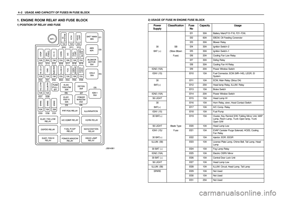
4–2WUSAGE AND CAPACITY OF FUSES IN FUSE BLOCK
1. ENGINE ROOM RELAY AND FUSE BLOCK
1) POSITION OF RELAY AND FUSE
2) USAGE OF FUSE IN ENGINE FUSE BLOCK
Power
Supply
ClassificationFuse
NoCapacityUsage
Ef130ABattery Main(F13~F16, F21~F24)
Ef260AEBCM, Oil Feeding Conenctor
Ef330ABlower Relay
30SBEf430AIgnition Switch–2
BAT (+)(Slow–BlownEf530AIgnition Switch–1
Fuse)Ef620ACooling Fan Low Relay
Ef730ADefog Relay
Ef830ACooling Fan HI Relay
IGN2 (15A)Ef920APower Window Switch
IGN1 (15)Ef1015AFuel Connector, ECM (MR–140), LEGR, EI
System
30Ef1110AECM, Main Relay (Sirius D4)
BAT(+)Ef1225AHead lamp Relay, ILLUM. Relay
Ef1315ABrake Switch
IGN2 (15A)Ef1420APower Window Switch
56 LIGHTEf1515AHead Lamp HI
30Ef1615AHorn Relay, siren, Hood Contact Switch
BAT(+)Ef1710AA/C Comp. Relay
IGN1 (15)Ef1815AFuel Pump
30 BAT(+)Ef1915ACluster, Key Remind S/W, Folding Mirror Unit, MAP
Lamp, Room Lamp, Trunk Open lamp, Trunk
Open S/W
56 LIGHTBlade TypeEf2010AHead Lamp Low
IGN1 (15)/FuseEf2115AEVAP Canister Purge Solenoid, HO2S, Cooling
Fan Relay
30 BAT(+)Ef2215Ainjector, EGR, EEGR
ILLUM. (58)Ef2310ALicense Plate Lamp, Chime Bell, Tail Lamp, Head
Lamp
30 BAT (+)Ef2415AFog Lamp Relay
IGN2 (15A)Ef2510AElectric OSRV Mirror
30 BAT (+)Ef2615ACentral Door Lock Unit
56 LIGHTEf2710AHead Lamp Low
ILLUM. (58)Ef2810AILLUM. Circuit, Head Lamp, Tail Lamp
SPAREEf2910ANot Used
Ef3015ANot Used
Ef3125ANot Used
Page 1082 of 2643
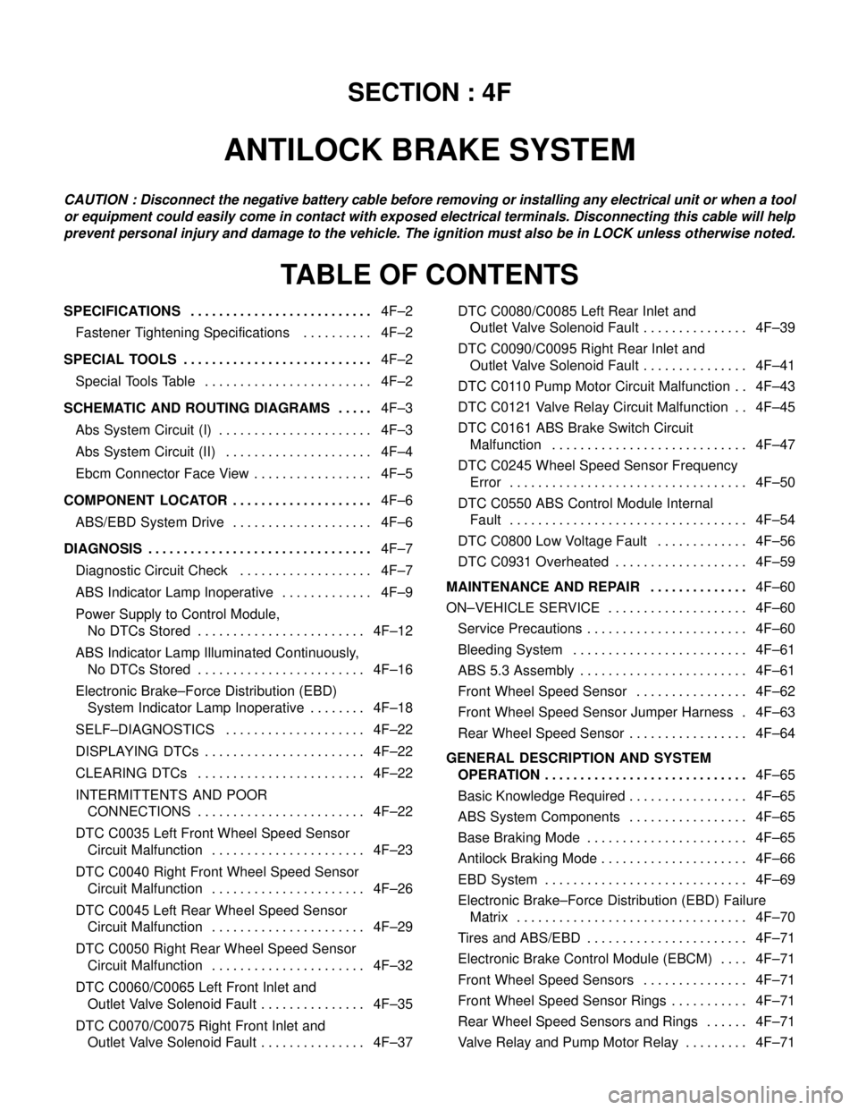
SECTION : 4F
ANTILOCK BRAKE SYSTEM
CAUTION : Disconnect the negative battery cable before removing or installing any electrical unit or when a tool
or equipment could easily come in contact with exposed electrical terminals. Disconnecting this cable will help
prevent personal injury and damage to the vehicle. The ignition must also be in LOCK unless otherwise noted.
TABLE OF CONTENTS
SPECIFICATIONS4F–2 . . . . . . . . . . . . . . . . . . . . . . . . . .
Fastener Tightening Specifications 4F–2. . . . . . . . . .
SPECIAL TOOLS4F–2 . . . . . . . . . . . . . . . . . . . . . . . . . . .
Special Tools Table 4F–2. . . . . . . . . . . . . . . . . . . . . . . .
SCHEMATIC AND ROUTING DIAGRAMS4F–3 . . . . .
Abs System Circuit (I) 4F–3. . . . . . . . . . . . . . . . . . . . . .
Abs System Circuit (II) 4F–4. . . . . . . . . . . . . . . . . . . . .
Ebcm Connector Face View 4F–5. . . . . . . . . . . . . . . . .
COMPONENT LOCATOR4F–6 . . . . . . . . . . . . . . . . . . . .
ABS/EBD System Drive 4F–6. . . . . . . . . . . . . . . . . . . .
DIAGNOSIS4F–7 . . . . . . . . . . . . . . . . . . . . . . . . . . . . . . . .
Diagnostic Circuit Check 4F–7. . . . . . . . . . . . . . . . . . .
ABS Indicator Lamp Inoperative 4F–9. . . . . . . . . . . . .
Power Supply to Control Module,
No DTCs Stored 4F–12. . . . . . . . . . . . . . . . . . . . . . . .
ABS Indicator Lamp Illuminated Continuously,
No DTCs Stored 4F–16. . . . . . . . . . . . . . . . . . . . . . . .
Electronic Brake–Force Distribution (EBD)
System Indicator Lamp Inoperative 4F–18. . . . . . . .
SELF–DIAGNOSTICS 4F–22. . . . . . . . . . . . . . . . . . . .
DISPLAYING DTCs 4F–22. . . . . . . . . . . . . . . . . . . . . . .
CLEARING DTCs 4F–22. . . . . . . . . . . . . . . . . . . . . . . .
INTERMITTENTS AND POOR
CONNECTIONS 4F–22. . . . . . . . . . . . . . . . . . . . . . . .
DTC C0035 Left Front Wheel Speed Sensor
Circuit Malfunction 4F–23. . . . . . . . . . . . . . . . . . . . . .
DTC C0040 Right Front Wheel Speed Sensor
Circuit Malfunction 4F–26. . . . . . . . . . . . . . . . . . . . . .
DTC C0045 Left Rear Wheel Speed Sensor
Circuit Malfunction 4F–29. . . . . . . . . . . . . . . . . . . . . .
DTC C0050 Right Rear Wheel Speed Sensor
Circuit Malfunction 4F–32. . . . . . . . . . . . . . . . . . . . . .
DTC C0060/C0065 Left Front Inlet and
Outlet Valve Solenoid Fault 4F–35. . . . . . . . . . . . . . .
DTC C0070/C0075 Right Front Inlet and
Outlet Valve Solenoid Fault 4F–37. . . . . . . . . . . . . . . DTC C0080/C0085 Left Rear Inlet and
Outlet Valve Solenoid Fault 4F–39. . . . . . . . . . . . . . .
DTC C0090/C0095 Right Rear Inlet and
Outlet Valve Solenoid Fault 4F–41. . . . . . . . . . . . . . .
DTC C0110 Pump Motor Circuit Malfunction 4F–43. .
DTC C0121 Valve Relay Circuit Malfunction 4F–45. .
DTC C0161 ABS Brake Switch Circuit
Malfunction 4F–47. . . . . . . . . . . . . . . . . . . . . . . . . . . .
DTC C0245 Wheel Speed Sensor Frequency
Error 4F–50. . . . . . . . . . . . . . . . . . . . . . . . . . . . . . . . . .
DTC C0550 ABS Control Module Internal
Fault 4F–54. . . . . . . . . . . . . . . . . . . . . . . . . . . . . . . . . .
DTC C0800 Low Voltage Fault 4F–56. . . . . . . . . . . . .
DTC C0931 Overheated 4F–59. . . . . . . . . . . . . . . . . . .
MAINTENANCE AND REPAIR4F–60 . . . . . . . . . . . . . .
ON–VEHICLE SERVICE 4F–60. . . . . . . . . . . . . . . . . . . .
Service Precautions 4F–60. . . . . . . . . . . . . . . . . . . . . . .
Bleeding System 4F–61. . . . . . . . . . . . . . . . . . . . . . . . .
ABS 5.3 Assembly 4F–61. . . . . . . . . . . . . . . . . . . . . . . .
Front Wheel Speed Sensor 4F–62. . . . . . . . . . . . . . . .
Front Wheel Speed Sensor Jumper Harness 4F–63.
Rear Wheel Speed Sensor 4F–64. . . . . . . . . . . . . . . . .
GENERAL DESCRIPTION AND SYSTEM
OPERATION4F–65 . . . . . . . . . . . . . . . . . . . . . . . . . . . . .
Basic Knowledge Required 4F–65. . . . . . . . . . . . . . . . .
ABS System Components 4F–65. . . . . . . . . . . . . . . . .
Base Braking Mode 4F–65. . . . . . . . . . . . . . . . . . . . . . .
Antilock Braking Mode 4F–66. . . . . . . . . . . . . . . . . . . . .
EBD System 4F–69. . . . . . . . . . . . . . . . . . . . . . . . . . . . .
Electronic Brake–Force Distribution (EBD) Failure
Matrix 4F–70. . . . . . . . . . . . . . . . . . . . . . . . . . . . . . . . .
Tires and ABS/EBD 4F–71. . . . . . . . . . . . . . . . . . . . . . .
Electronic Brake Control Module (EBCM) 4F–71. . . .
Front Wheel Speed Sensors 4F–71. . . . . . . . . . . . . . .
Front Wheel Speed Sensor Rings 4F–71. . . . . . . . . . .
Rear Wheel Speed Sensors and Rings 4F–71. . . . . .
Valve Relay and Pump Motor Relay 4F–71. . . . . . . . .
Page 1103 of 2643
4F – 22IANTILOCK BRAKE SYSTEM
DAEWOO V–121 BL4
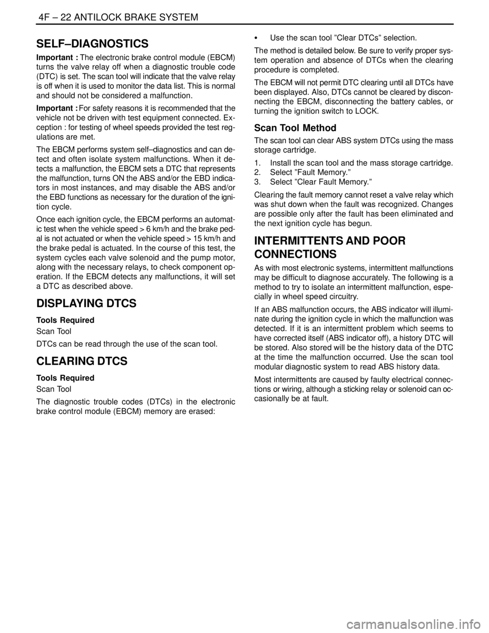
SELF–DIAGNOSTICS
Important : The electronic brake control module (EBCM)
turns the valve relay off when a diagnostic trouble code
(DTC) is set. The scan tool will indicate that the valve relay
is off when it is used to monitor the data list. This is normal
and should not be considered a malfunction.
Important : For safety reasons it is recommended that the
vehicle not be driven with test equipment connected. Ex-
ception : for testing of wheel speeds provided the test reg-
ulations are met.
The EBCM performs system self–diagnostics and can de-
tect and often isolate system malfunctions. When it de-
tects a malfunction, the EBCM sets a DTC that represents
the malfunction, turns ON the ABS and/or the EBD indica-
tors in most instances, and may disable the ABS and/or
the EBD functions as necessary for the duration of the igni-
tion cycle.
Once each ignition cycle, the EBCM performs an automat-
ic test when the vehicle speed > 6 km/h and the brake ped-
al is not actuated or when the vehicle speed > 15 km/h and
the brake pedal is actuated. In the course of this test, the
system cycles each valve solenoid and the pump motor,
along with the necessary relays, to check component op-
eration. If the EBCM detects any malfunctions, it will set
a DTC as described above.
DISPLAYING DTCS
Tools Required
Scan Tool
DTCs can be read through the use of the scan tool.
CLEARING DTCS
Tools Required
Scan Tool
The diagnostic trouble codes (DTCs) in the electronic
brake control module (EBCM) memory are erased:S Use the scan tool ”Clear DTCs” selection.
The method is detailed below. Be sure to verify proper sys-
tem operation and absence of DTCs when the clearing
procedure is completed.
The EBCM will not permit DTC clearing until all DTCs have
been displayed. Also, DTCs cannot be cleared by discon-
necting the EBCM, disconnecting the battery cables, or
turning the ignition switch to LOCK.
Scan Tool Method
The scan tool can clear ABS system DTCs using the mass
storage cartridge.
1. Install the scan tool and the mass storage cartridge.
2. Select ”Fault Memory.”
3. Select ”Clear Fault Memory.”
Clearing the fault memory cannot reset a valve relay which
was shut down when the fault was recognized. Changes
are possible only after the fault has been eliminated and
the next ignition cycle has begun.
INTERMITTENTS AND POOR
CONNECTIONS
As with most electronic systems, intermittent malfunctions
may be difficult to diagnose accurately. The following is a
method to try to isolate an intermittent malfunction, espe-
cially in wheel speed circuitry.
If an ABS malfunction occurs, the ABS indicator will illumi-
nate during the ignition cycle in which the malfunction was
detected. If it is an intermittent problem which seems to
have corrected itself (ABS indicator off), a history DTC will
be stored. Also stored will be the history data of the DTC
at the time the malfunction occurred. Use the scan tool
modular diagnostic system to read ABS history data.
Most intermittents are caused by faulty electrical connec-
tions or wiring, although a sticking relay or solenoid can oc-
casionally be at fault.
Page 1116 of 2643
ANTILOCK BRAKE SYSTEM 4F – 35
DAEWOO V–121 BL4
J3B14F09
DLC
(Data Link
Connector)
EBCM
DK BLUDK BLU
BLK/WHTC202
C110
11 2
1912 19
G106
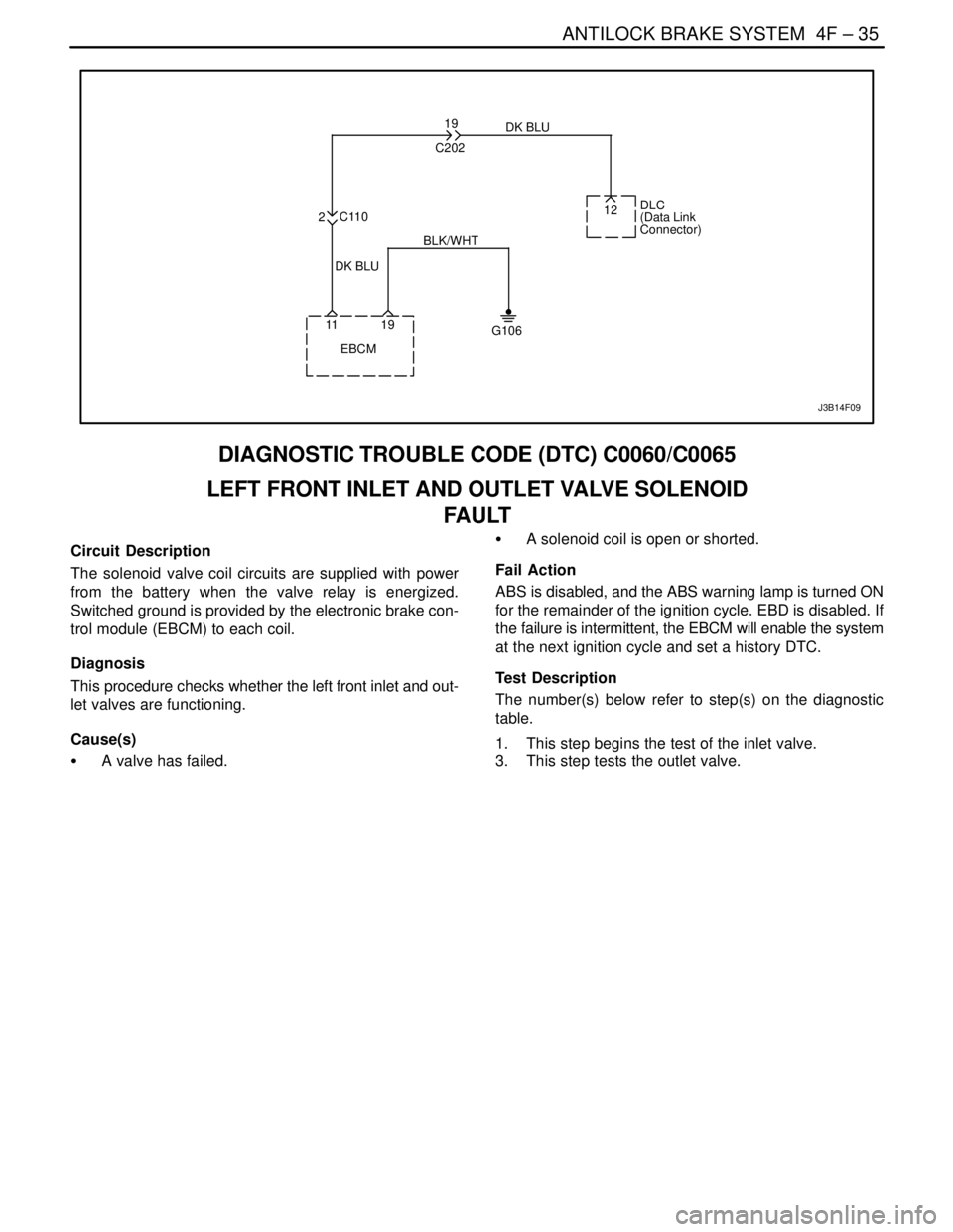
DIAGNOSTIC TROUBLE CODE (DTC) C0060/C0065
LEFT FRONT INLET AND OUTLET VALVE SOLENOID
FAULT
Circuit Description
The solenoid valve coil circuits are supplied with power
from the battery when the valve relay is energized.
Switched ground is provided by the electronic brake con-
trol module (EBCM) to each coil.
Diagnosis
This procedure checks whether the left front inlet and out-
let valves are functioning.
Cause(s)
S A valve has failed.S A solenoid coil is open or shorted.
Fail Action
ABS is disabled, and the ABS warning lamp is turned ON
for the remainder of the ignition cycle. EBD is disabled. If
the failure is intermittent, the EBCM will enable the system
at the next ignition cycle and set a history DTC.
Test Description
The number(s) below refer to step(s) on the diagnostic
table.
1. This step begins the test of the inlet valve.
3. This step tests the outlet valve.