2004 DAEWOO LACETTI Map sensor
[x] Cancel search: Map sensorPage 92 of 2643

1.4L/1.6L DOHC ENGINE MECHANICAL 1C1 – 49
DAEWOO V–121 BL4
17. Disconnect the oxygen (O2) sensor connector, if
equipped.
18. Disconnect the fuel injector harness connectors.
19. Disconnect the MAT, MAP sensor connectors.
20. Disconnect the throttle position sensor (TPS) con-
nector.
21. Disconnect the generator voltage regulator connec-
tor and power lead.
22. Remove the electrical harness clamp bolt.
23. Disconnect all of the necessary vacuum lines, in-
cluding the brake booster vacuum hose.
24. Disconnect the fuel feed line at the fuel rail.
25. Disconnect the throttle cable from the throttle body
and the intake manifold bracket.
26. Disconnect the surge tank coolant hose at the
throttle body.
27. Disconnect the heater outlet hose at the coolant
pipe.
28. Disconnect the heater inlet hose from the cylinder
head.
29. Disconnect the surge tank coolant hose from the
coolant pipe.
30. Disconnect the lower radiator hose from the coolant
pipe. Disconnect the starter solenoid ”S” terminal
wire. Remove the A/C compressor, if equipped. Re-
fer to Section 7B, Manual Control Heating, Ventila-
tion, and Air Conditioning Systems.
31. Remove the catalytic converter retaining nuts from
the exhaust pipe.
32. Remove the exhaust pipe.
Page 95 of 2643

1C1 – 52I1.4L/1.6L DOHC ENGINE MECHANICAL
DAEWOO V–121 BL4
18. Connect the power steering pressure hose.
19. Connect the power steering return hose.
20. Install the A/C compressor, if equipped. Refer to
Section 7B, Manual Control Heating, Ventilation,
and Air Conditioning Systems.
21. Install the generator. Refer to Section 1E, Engine
Electrical.
22. Install the serpentine accessory drive belt. Refer to
Section 6B, Power Steering Pump.
23. Install the right front wheel well splash shield.
24. Install the right front wheel. Refer to Section 2E,
Tires and Wheels.
25. Connect the fuel feed line to the fuel rail.
26. Connect all of the necessary vacuum lines, includ-
ing the brake booster vacuum hose.
27. Connect the O2 sensor connector, if equipped.
28. Connect the starter solenoid ”S” terminal wire and
power lead.
29. Connect the generator voltage regulator connector
and power lead.
30. Connect the CTS connector.
31. Connect the MAP, MAT sensor connectors.
32. Connect the TPS connector.
33. Install the electrical wiring harness clamp at the
intake manifold support bracket.
34. Connect the fuel injector harness connectors.
35. Connect the electrical connector at the DIS coil and
the ECM ground terminal at the starter.
36. Install the air cleaner outlet hose between the
throttle body and the air cleaner housing.
37. Connect the breather tubes to the camshaft cover.
38. Install the cooling system radiator and the engine
cooling fans. Refer to Section 1D, Engine Cooling.
Page 159 of 2643

1.8L DOHC ENGINE MECHANICAL 1C2 – 39
DAEWOO V–121 BL4
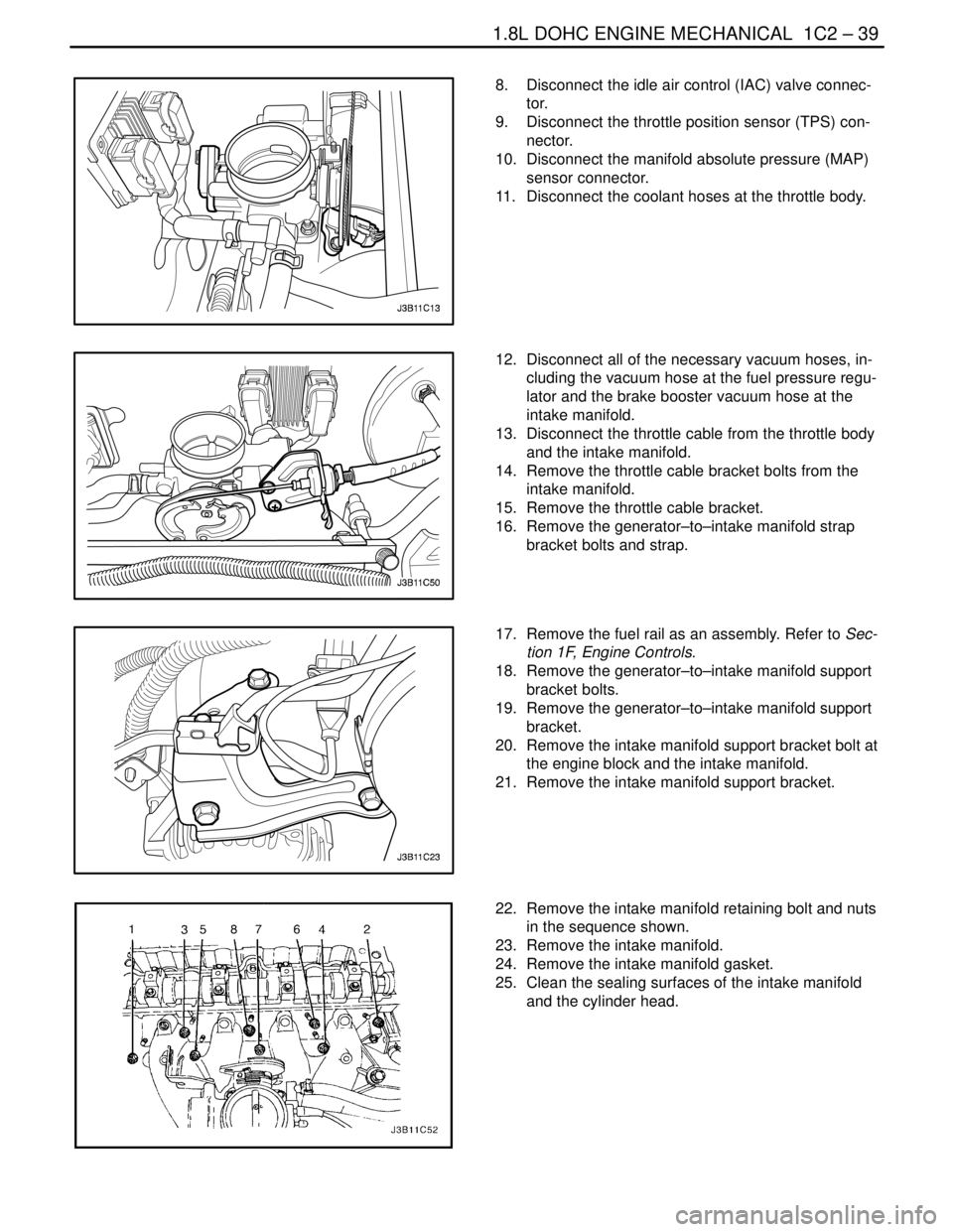
8. Disconnect the idle air control (IAC) valve connec-
tor.
9. Disconnect the throttle position sensor (TPS) con-
nector.
10. Disconnect the manifold absolute pressure (MAP)
sensor connector.
11. Disconnect the coolant hoses at the throttle body.
12. Disconnect all of the necessary vacuum hoses, in-
cluding the vacuum hose at the fuel pressure regu-
lator and the brake booster vacuum hose at the
intake manifold.
13. Disconnect the throttle cable from the throttle body
and the intake manifold.
14. Remove the throttle cable bracket bolts from the
intake manifold.
15. Remove the throttle cable bracket.
16. Remove the generator–to–intake manifold strap
bracket bolts and strap.
17. Remove the fuel rail as an assembly. Refer to Sec-
tion 1F, Engine Controls.
18. Remove the generator–to–intake manifold support
bracket bolts.
19. Remove the generator–to–intake manifold support
bracket.
20. Remove the intake manifold support bracket bolt at
the engine block and the intake manifold.
21. Remove the intake manifold support bracket.
22. Remove the intake manifold retaining bolt and nuts
in the sequence shown.
23. Remove the intake manifold.
24. Remove the intake manifold gasket.
25. Clean the sealing surfaces of the intake manifold
and the cylinder head.
Page 161 of 2643

1.8L DOHC ENGINE MECHANICAL 1C2 – 41
DAEWOO V–121 BL4
14. Connect the MAP sensor connector.
15. Connect the coolant hoses to the throttle body.
16. Connect the IAC valve connector.
17. Connect the TPS connector.
18. Connect the air cleaner outlet hose to the throttle
body.
19. Connect the MAT sensor connector.
20. Connect the CCP and EGR solenoid at the intake
manifold and tighten the bracket bolt.
Tighten
Tighten the charcoal canister purge and exhaust gas
recirculation solenoid bracket bolt to 5 NSm (44 lb–in).
21. Install the fuel pump fuse.
22. Connect the negative battery cable.
23. Refill the engine cooling system. Refer to Section
1D, Engine Cooling.
EXHAUST MANIFOLD
Removal Procedure
1. Disconnect the negative battery cable.
2. Disconnect the oxygen (O2) sensor connector, if
equipped.
3. Remove the exhaust manifold heat shield bolts.
4. Remove the exhaust manifold heat shield.
5. Remove the exhaust flex pipe retaining nuts from
the exhaust manifold studs.
Page 170 of 2643

1C2 – 50I1.8L DOHC ENGINE MECHANICAL
DAEWOO V–121 BL4
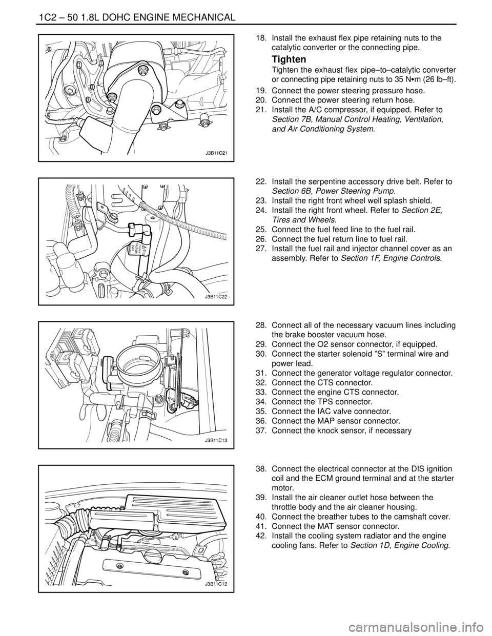
18. Install the exhaust flex pipe retaining nuts to the
catalytic converter or the connecting pipe.
Tighten
Tighten the exhaust flex pipe–to–catalytic converter
or connecting pipe retaining nuts to 35 NSm (26 lb–ft).
19. Connect the power steering pressure hose.
20. Connect the power steering return hose.
21. Install the A/C compressor, if equipped. Refer to
Section 7B, Manual Control Heating, Ventilation,
and Air Conditioning System.
22. Install the serpentine accessory drive belt. Refer to
Section 6B, Power Steering Pump.
23. Install the right front wheel well splash shield.
24. Install the right front wheel. Refer to Section 2E,
Tires and Wheels.
25. Connect the fuel feed line to the fuel rail.
26. Connect the fuel return line to fuel rail.
27. Install the fuel rail and injector channel cover as an
assembly. Refer to Section 1F, Engine Controls.
28. Connect all of the necessary vacuum lines including
the brake booster vacuum hose.
29. Connect the O2 sensor connector, if equipped.
30. Connect the starter solenoid ”S” terminal wire and
power lead.
31. Connect the generator voltage regulator connector.
32. Connect the CTS connector.
33. Connect the engine CTS connector.
34. Connect the TPS connector.
35. Connect the IAC valve connector.
36. Connect the MAP sensor connector.
37. Connect the knock sensor, if necessary
38. Connect the electrical connector at the DIS ignition
coil and the ECM ground terminal and at the starter
motor.
39. Install the air cleaner outlet hose between the
throttle body and the air cleaner housing.
40. Connect the breather tubes to the camshaft cover.
41. Connect the MAT sensor connector.
42. Install the cooling system radiator and the engine
cooling fans. Refer to Section 1D, Engine Cooling.
Page 252 of 2643

1F – 6IENGINE CONTROLS
DAEWOO V–121 BL4
SPECIFICATIONS
ENGINE DATA DISPLAY TABLES
Engine Data Display
Parameter
ScalingValue
Desired Idle SpeedRPMECM idle command (varies with temperature)
Engine RPMRPM± 50 RPM from desired RPM in drive (A/T) ± 50 RPM
from desired RPM in neutral (M/T)
MAPkPa29 – 55 (varies with manifold and barometric pressure)
Throttle Position VoltV0 v
Start–up IAT°Cvaries
Intake Air Temperature°C10 – 90 °C
Coolant Temperature (Start–up)°Cvaries
Engine Coolant Temperature°C85 – 105 °C
IAC Motor Position–1 – 50
O2 Sensor (B1–S1)mV1–1000 mV (varies continuously)
O2 Sensor (B1–S2)mV1–1000 mV (varies continuously)
Fuel System StatusClosed Loop/Open
Loop”Closed Loop” (may enter ”Open Loop” at extended idle)
Rich/Lean (B1–S1)Rich/Leanvaries
Lean to Rich AveragemS10 –211 ms or 0 ms
Rich to Lean AveragemS10 –211 ms or 0 ms
Engine Load Value%0 – 100 % (varies)
Short Term Fuel Trim%–30 – 30%
Long Term Fuel Trim%–30 – 30%
Linear EGR FeedbackVvaries
EGR Duty Cycle%0 %
EGR EWMA Result–< = 0
Spark Advance°varies
MIL OdometerKm0 Km
MIL On TimeMin0 Min
Base Injection PWMmS1.0 – 5.0 ms
Barometric PressurekPavaries with altitude
Ignition VoltageV13.5 – 14.8 V
Air/Fuel RatioRatio14.6 (Closed Loop Enable)
Calculated Air FlowG/Svaries
Total Misfire (Current)–0
Misfire History Cyl. 1–0
Misfire History Cyl. 2–0
Misfire History Cyl. 3–0
Misfire History Cyl. 4–0
Vehicle SpeedKm/H0 Km/H
A/C PressureVvaries
Page 254 of 2643

1F – 8IENGINE CONTROLS
DAEWOO V–121 BL4
EGR Desired Position
The desired exhaust gas recirculation (EGR) position is
the commanded EGR position. The ECM calculates the
desired EGR position. The higher the percentage, the lon-
ger the ECM is commanding the EGR valve ON.
Engine Load
Indicates engine load based on manifold absolute pres-
sure. The higher the percentage, the more load the engine
is under.
Engine Run Time
The engine run time is a measure of how long the engine
has been running. When the engine stops running, the tim-
er resets to zero.
Engine Speed
Engine Speed is computed by the ECM from the fuel con-
trol reference input. It should remain close to desired idle
under the various engine loads with the engine idling.
Fan
The Fan Control (FC) Relay is commanded by the ECM.
The FC Relay displays the command as ON or OFF.
Fuel Level Sensor
The Fuel Level Sensor monitors the fuel level in the tank.
The Fuel Level Sensor monitors the rate of change of the
air pressure in the EVAP system. Several of the Enhanced
EVAP System diagnostics are dependent upon the correct
fuel level.
Fuel System Status
The Closed Loop is displayed indicating that the ECM is
controlling the fuel delivery according to the Front Heated
Oxygen Sensor (HO2S1) voltage as close to an air/fuel ra-
tio of 14.7 to 1 as possible.
IAC Position
The scan tool displays the ECM command for the Idle Air
Control (IAC) pintle position in counts. The higher the
number of counts, the greater the commanded idle speed
reads. The Idle Air Control responds to changes in the en-
gine load in order to maintain the desired idle rpm.
Ignition 1 (Voltage)
The ignition volts represent the system voltage measured
by the ECM at the ignition feed circuit.
Intake Air Temperature
The ECM converts the resistance of the Intake Air Tem-
perature (IAT) sensor to degrees in the same manner as
the engine coolant temperature (ECT) sensor. In take air
temperature is used by the ECM to adjust fuel delivery and
spark timing according to incoming air density.Knock Present
The KS Noise Channel indicates when the ECM detects
the KS signal. The ECM should display NO at idle.
Long Term FT
The Long Term Fuel Trim (FT) is derived from the short
term fuel trim value. The Long Term FT is used for the long
term correction of the fuel delivery. A value of 128 counts
(0%) indicates that the fuel delivery requires no com-
pensation in order to maintain a 14.7:1 air to fuel ratio. A
value below 128 counts means that the fuel system is too
rich and the fuel delivery is being reduced. The ECM is de-
creasing the injector pulse width. A value above 128
counts indicates that a lean condition exists for which the
ECM is compensating.
MAP
The Manifold Absolute Pressure (MAP) sensor measures
the change in the intake manifold pressure which results
from engine load and speed changes. As the intake man-
ifold pressure increases, the air density in the intake also
increases and the additional fuel is required.
Misfire History #1–4
Indicates the number of misfires that have occurred after
195 current misfires have been counted. The current mis-
fire counter will add its misfires to the history misfire count-
er after 195 total misfires have taken place. If 1 cylinder is
misfiring, the misfiring current counter will have 195 mis-
fires counted before adding to its history counter. If 2 cylin-
ders are misfiring, the misfiring current counter will add to
their history counters after 97 misfires. The counter incre-
ments only after a misfire diagnostic trouble code (DTC)
has been set.
Front Heated Oxygen Sensor
The pre–converter Front Heated Oxygen Sensor
(HO2S1) reading represents the exhaust oxygen sensor
output voltage. This voltage will fluctuate constantly be-
tween 100 mv (lean exhaust) and 900 mv (rich exhaust)
when the system is operating in a Closed Loop.
Rear Heated Oxygen Sensor
The post–converter Rear Heated Oxygen Sensor
(HO2S2) represents the exhaust oxygen output voltage
past the catalytic converter. This voltage remains inactive,
or the voltage will appear lazy within a range of 100 mv
(lean exhaust) and 900 mv (rich exhaust) when operating
in a Closed Loop.
Short Term FT
The Short Term FT represents a short term correction to
fuel delivery by the ECM in response to the amount of time
the oxygen sensor voltage spends above or below the 450
mv threshold. If the oxygen sensor has mainly been below
450 mv, indicating a lean air/fuel mixture, short term fuel
trim will increase to tell the ECM to add fuel. If the oxygen
sensor voltage stays mainly above the threshold, the ECM
will reduce fuel delivery to compensate for the indicated
rich condition.
Page 274 of 2643

1F – 28IENGINE CONTROLS
DAEWOO V–121 BL4
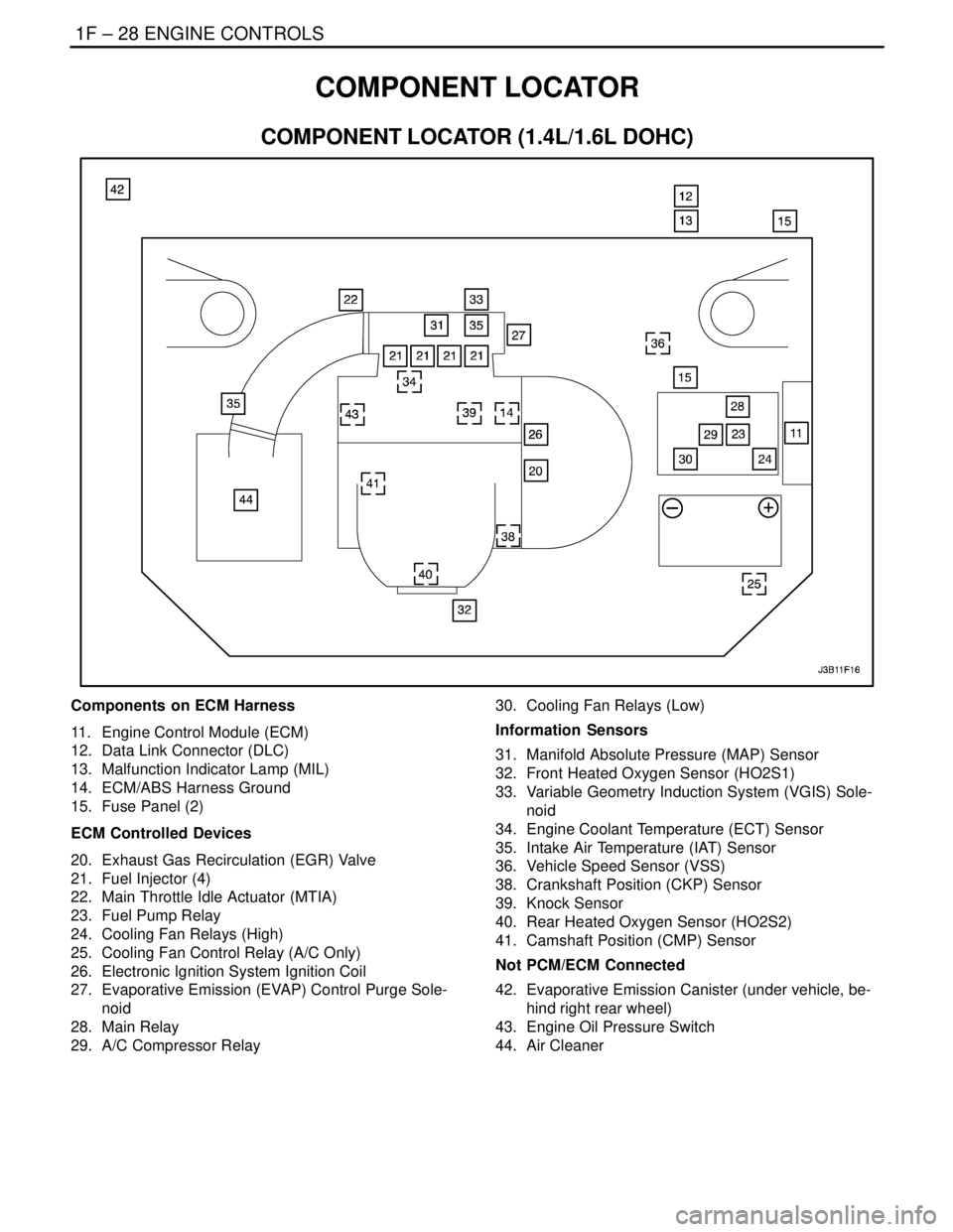
COMPONENT LOCATOR
COMPONENT LOCATOR (1.4L/1.6L DOHC)
Components on ECM Harness
11. Engine Control Module (ECM)
12. Data Link Connector (DLC)
13. Malfunction Indicator Lamp (MIL)
14. ECM/ABS Harness Ground
15. Fuse Panel (2)
ECM Controlled Devices
20. Exhaust Gas Recirculation (EGR) Valve
21. Fuel Injector (4)
22. Main Throttle Idle Actuator (MTIA)
23. Fuel Pump Relay
24. Cooling Fan Relays (High)
25. Cooling Fan Control Relay (A/C Only)
26. Electronic Ignition System Ignition Coil
27. Evaporative Emission (EVAP) Control Purge Sole-
noid
28. Main Relay
29. A/C Compressor Relay30. Cooling Fan Relays (Low)
Information Sensors
31. Manifold Absolute Pressure (MAP) Sensor
32. Front Heated Oxygen Sensor (HO2S1)
33. Variable Geometry Induction System (VGIS) Sole-
noid
34. Engine Coolant Temperature (ECT) Sensor
35. Intake Air Temperature (IAT) Sensor
36. Vehicle Speed Sensor (VSS)
38. Crankshaft Position (CKP) Sensor
39. Knock Sensor
40. Rear Heated Oxygen Sensor (HO2S2)
41. Camshaft Position (CMP) Sensor
Not PCM/ECM Connected
42. Evaporative Emission Canister (under vehicle, be-
hind right rear wheel)
43. Engine Oil Pressure Switch
44. Air Cleaner