2003 NISSAN X-TRAIL turn signal
[x] Cancel search: turn signalPage 1933 of 3066
![NISSAN X-TRAIL 2003 Electronic Repair Manual START SIGNAL
EC-819
[YD]
C
D
E
F
G
H
I
J
K
L
MA
EC
Diagnostic ProcedureEBS0035T
1.CHECK START SIGNAL OVERALL FUNCTION
With CONSULT-II
1. Turn ignition switch “ON”.
2. Check “START SIGNAL” in � NISSAN X-TRAIL 2003 Electronic Repair Manual START SIGNAL
EC-819
[YD]
C
D
E
F
G
H
I
J
K
L
MA
EC
Diagnostic ProcedureEBS0035T
1.CHECK START SIGNAL OVERALL FUNCTION
With CONSULT-II
1. Turn ignition switch “ON”.
2. Check “START SIGNAL” in �](/manual-img/5/57402/w960_57402-1932.png)
START SIGNAL
EC-819
[YD]
C
D
E
F
G
H
I
J
K
L
MA
EC
Diagnostic ProcedureEBS0035T
1.CHECK START SIGNAL OVERALL FUNCTION
With CONSULT-II
1. Turn ignition switch “ON”.
2. Check “START SIGNAL” in “DATA MONITOR” mode with CON-
SULT-II under the following conditions.
OK or NG
OK >>INSPECTION END
NG >> GO TO 2.
2.CHECK START SIGNAL INPUT SIGNAL CIRCUIT
1. Turn ignition switch “OFF”.
2. Disconnect ECM harness connector and ignition switch harness connector.
3. Check harness continuity between ECM terminal D27 and ignition switch terminal 6. Refer to Wiring Dia-
gram.
4. Also check harness for short to ground and short to power.
OK or NG
OK >> GO TO 4.
NG >> GO TO 3.
3.DETECT MALFUNCTIONING PART
Check the following.
lHarness connectors M63, F30
l10A fuse
lFuse block (J/B) connectors M1, E102
lHarness for open or short between ECM and ignition switch
>> Repair open circuit or short to ground or short to power in harness or connectors.
4.CHECK INTERMITTENT INCIDENT
Refer toEC-699, "
TROUBLE DIAGNOSIS FOR INTERMITTENT INCIDENT".
>>INSPECTION END
Condition "START SIGNAL"
Ignition switch "ON" OFF
Ignition switch "START" ON
PBIB0433E
Continuity should exist.
Page 1934 of 3066
![NISSAN X-TRAIL 2003 Electronic Repair Manual EC-820
[YD]
POWER STEERING OIL PRESSURE SWITCH
POWER STEERING OIL PRESSURE SWITCH
PFP:49761
Component DescriptionEBS003PS
The power steering oil pressure switch is attached to the power
steering high- NISSAN X-TRAIL 2003 Electronic Repair Manual EC-820
[YD]
POWER STEERING OIL PRESSURE SWITCH
POWER STEERING OIL PRESSURE SWITCH
PFP:49761
Component DescriptionEBS003PS
The power steering oil pressure switch is attached to the power
steering high-](/manual-img/5/57402/w960_57402-1933.png)
EC-820
[YD]
POWER STEERING OIL PRESSURE SWITCH
POWER STEERING OIL PRESSURE SWITCH
PFP:49761
Component DescriptionEBS003PS
The power steering oil pressure switch is attached to the power
steering high-pressure tube and detects a power steering load.
When a power steering load is detected, it signals the ECM. The
ECM adjusts the fuel injector pulse width to increase the idle speed
and adjust for the increased load.
CONSULT-II Reference Value in Data Monitor ModeEBS003PT
Specification data are reference values.
ECM Terminals and Reference ValueEBS003PZ
Specification data are reference values, and are measured between each terminal and ground.
CAUTION:
Do not use ECM ground terminals when measuring input/output voltage. Doing so may result in dam-
age to the ECM's transistor. Use a ground other than ECM terminals, such as the ground.
PBIB0375E
MONITOR ITEM CONDITION SPECIFICATION
PW/ST SIGNAL
lEngine: After warming up, idle the
engineSteering wheel is in neutral position.
(Forward direction)OFF
Steering wheel is turned. ON
TER-
MINAL
NO.WIRE
COLORITEM CONDITION DATA (DC Voltage)
E12 P/BPower steering oil pressure
switch[Engine is running]
lSteering wheel is being turnedApproximately 0V
[Engine is running]
lSteering wheel is not being turnedBATTERY VOLTAGE
(11 - 14V)
Page 1936 of 3066
![NISSAN X-TRAIL 2003 Electronic Repair Manual EC-822
[YD]
POWER STEERING OIL PRESSURE SWITCH
Diagnostic Procedure
EBS003PV
1.CHECK OVERALL FUNCTION
With CONSULT-II
1. Start engine.
2. Check “PW/ST SIGNAL” in “DATA MONITOR” mode with CON-
NISSAN X-TRAIL 2003 Electronic Repair Manual EC-822
[YD]
POWER STEERING OIL PRESSURE SWITCH
Diagnostic Procedure
EBS003PV
1.CHECK OVERALL FUNCTION
With CONSULT-II
1. Start engine.
2. Check “PW/ST SIGNAL” in “DATA MONITOR” mode with CON-](/manual-img/5/57402/w960_57402-1935.png)
EC-822
[YD]
POWER STEERING OIL PRESSURE SWITCH
Diagnostic Procedure
EBS003PV
1.CHECK OVERALL FUNCTION
With CONSULT-II
1. Start engine.
2. Check “PW/ST SIGNAL” in “DATA MONITOR” mode with CON-
SULT-II under the following conditions.
OK or NG
OK >>INSPECTION END
NG >> GO TO 2.
2.CHECK POWER STEERING OIL PRESSURE SWITCH GROUND CIRCUIT FOR OPEN AND SHORT
1. Turn ignition switch “OFF”.
2. Disconnect power steering oil pressure switch harness connec-
tor.
3. Check harness continuity between power steering oil pressure
switch terminal 2 and engine ground. Refer to Wiring Diagram.
4. Also check harness for short to power.
OK or NG
OK >> GO TO 3.
NG >> Repair open circuit or short to power in harness or con-
nectors.
3.CHECK POWER STEERING OIL PRESSURE SWITCH INPUT SIGNAL CIRCUIT FOR OPEN AND
SHORT
1. Disconnect ECM harness connector.
2. Check harness continuity between ECM terminal E12 and power steering oil pressure switch terminal 1.
Refer to Wiring Diagram.
3. Also check harness for short to ground and short to power.
OK or NG
OK >> GO TO 4.
NG >> Repair open circuit or short to ground or short to power in harness or connectors.
4.CHECK POWER STEERING OIL PRESSURE SWITCH
Refer toEC-823, "
Component Inspection".
OK or NG
OK >> GO TO 5.
NG >> Replace power steering oil pressure switch.
Conditions PW/ST SIGNAL
Steering in neutral position OFF
Steering is turned ON
PBIB0434E
Continuity should exist.
PBIB0375E
Continuity should exist.
Page 2319 of 3066

GW-16
REAR WINDOW DEFOGGER
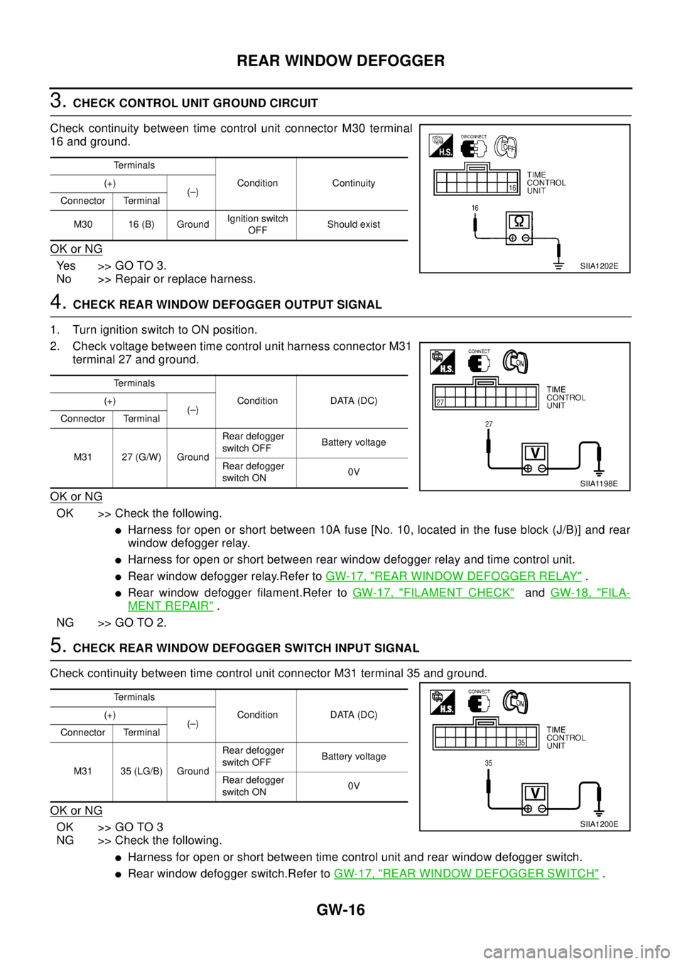
3.CHECK CONTROL UNIT GROUND CIRCUIT
Check continuity between time control unit connector M30 terminal
16 and ground.
OK or NG
Yes >>GOTO3.
No >> Repair or replace harness.
4.CHECK REAR WINDOW DEFOGGER OUTPUT SIGNAL
1. Turn ignition switch to ON position.
2. Check voltage between time control unit harness connector M31
terminal 27 and ground.
OK or NG
OK >> Check the following.
lHarness for open or short between 10A fuse [No. 10, located in the fuse block (J/B)] and rear
window defogger relay.
lHarness for open or short between rear window defogger relay and time control unit.
lRear window defogger relay.Refer toGW-17, "REAR WINDOW DEFOGGER RELAY".
lRear window defogger filament.Refer toGW-17, "FILAMENT CHECK"andGW-18, "FILA-
MENT REPAIR".
NG >> GO TO 2.
5.CHECK REAR WINDOW DEFOGGER SWITCH INPUT SIGNAL
Check continuity between time control unit connector M31 terminal 35 and ground.
OK or NG
OK >> GO TO 3
NG >> Check the following.
lHarness for open or short between time control unit and rear window defogger switch.
lRear window defogger switch.Refer toGW-17, "REAR WINDOW DEFOGGER SWITCH".
Te r m i n a l s
Condition Continuity (+)
(–)
Connector Terminal
M30 16 (B) GroundIgnition switch
OFFShould exist
SIIA1202E
Te r m i n a l s
Condition DATA (DC) (+)
(–)
Connector Terminal
M31 27 (G/W) GroundRear defogger
switch OFFBattery voltage
Rear defogger
switch ON0V
SIIA1198E
Te r m i n a l s
Condition DATA (DC) (+)
(–)
Connector Terminal
M31 35 (LG/B) GroundRear defogger
switch OFFBattery voltage
Rear defogger
switch ON0V
SIIA1200E
Page 2324 of 3066

POWER WINDOW SYSTEM
GW-21
C
D
E
F
G
H
J
K
L
MA
B
GW
lthrough power window main switch terminal 1 (LHD models) or 7 (RHD models).
Then, the motor raises the window until the switch is released.
WINDOW DOWN
When the driver's window switch in the power window main switch is pressed in the down position, power is
supplied
lto driver side power window regulator terminal 3
lthrough power window main switch terminal 1 (LHD models) or 7 (RHD models)
Ground is supplied
lto driver side power window regulator terminal 1
lthrough power window main switch terminal 2 (LHD models) or 6 (RHD models).
Then, the motor lowers the window until the switch is released.
Front door (Passenger Side)
Ground is supplied
lto power window main switch terminal 19
lthrough body grounds M27 and M70.
NOTE:
Numbers in parentheses are terminal numbers, when power window switch is pressed in the UP and DOWN
positions respectively.
POWER WINDOW MAIN SWITCH OPERATION
Power is supplied
lthrough power window main switch (4, 3) (LHD models) or (4, 5) (RHD models)
lto passenger side power window switch (3, 4).
The subsequent operation is the same as the passenger side power window switch operation.
PASSENGER SIDE POWER WINDOW SWITCH OPERATION
Power is supplied
lthrough passenger side power window switch (1, 2)
lto passenger side power window regulator (1, 2).
Ground is supplied
lto passenger side power window regulator (1, 2)
lthrough passenger side power window switch (1, 2)
lto passenger side power window switch (3 ,4)
lthrough power window main switch (4, 3) (LHD models) or (4, 5) (RHD models).
Then, the ,motor raises or lowers the window until the switch is released.
Rear door
Rear door windows will raise and lower in the same manner as passenger's door window.
AUTO OPERATION
The power window AUTO feature enables the driver to open or close the driver's window without holding the
window switch in the down or up position.
The AUTO feature operates on the driver's window.
POWER WINDOW LOCK
The power window lock is designed to lock operation of all windows except for driver's window.
When the lock switch is pressed to pressed to lock position, ground of the sub–switches in the power window
main switch is disconnected.This prevents the power window motors from operating.
TIME FUNCTION
With the timer function, driver power window can be operated for approximately 15 minutes after ignition
switch is turned OFF (positions other than ON). However, the timer will be reset when a specific signal, such
as driver door open (door switch ON)®close (door switch OFF), or ignition switch OFF®ON, is input.
DRIVER WINDOW ANTI–PINCH FUNCTION
During raising operation of driver power window, if door control module detects that foreign object is pinched,
power window lowers approximately 150 mm (5.91 in).
Page 2341 of 3066

GW-38
POWER WINDOW SYSTEM
Trouble Diagnoses
EIS001SF
3 R/W Power window DOWN signalPower window switch DOWN
operation.Approx. 0
Power window switch
UP operation.Approx. 0
Power window switch DOWN
operation.Battery voltage
Power window switch
UP operation.Battery voltage
Other than above. Approx. 0
4 L/OR Power window UP signalPower window switch
UP operation.Approx. 0
Power window switch DOWN
operation.Approx. 0
Power window switch
UP operation.Battery voltage
Power window switch DOWN
operation.Battery voltage
Other than above. Approx. 0
5W/RPower window switch power
supply— Battery voltage TERMINALWIRE
COLORITEM CONDITION VOLTAGE (V)
Symptom Possible cause Repair order
None of the power windows can be
operated using any switch.1. 10A fuse, 40A fusible link
2. M4 circuit breaker
3. Power window relay
4. M4 circuit breaker
5. Ground circuit
6. Power window main switch1. Check 10A fuse [No. 5, located in fuse block (J/B)]
Turn ignition switch “ON” and verify positive battery
voltage is present at terminal 1 (G) of power window
relay.
2. Check 40A fusible link (letterB, located in fuse and
fusible link box) and M4 circuit breaker. Verify positive
battery voltage is present at terminal 3 (W) of power
window relay.
3. Check M4 circuit breaker.
4. Check power window relay.
5. Check the following:
–Check harness between M4 circuit breaker and 40A
fusible link (letterB,located in fuse and fusible link
box).
–Check harness between M4 circuibt breaker and
power window main switch terminal 5 (LHD models)
or 3 (RHD models)
6. Check the following
–Check ground circuit of power window main switch.
–Check power window relay ground circuit.
–Check power window main switch.
Driver side power window cannot be
operated but other windows can be
operated.1. Driver side power window regula-
tor circuit
2. Driver side power window regula-
tor
3. Power window main switch1. Check harness between power window main switch
and driver side power window regulator for open or
short circuit.
2. Check driver side power window regulator.
3. Check power window main switch.
Page 2365 of 3066

IDX-8
ALPHABETICAL INDEX
SRS - See Supplemental Restraint System .....SRS-5
SRS - Wiring diagram/LHD .............................SRS-10
SRS - Wiring diagram/RHD ............................SRS-12
SRS Trouble diagnoses ....................................SRS-7
Stall test (A/T) ......................................AT-65,AT-287
Standardized relay .............................................PG-74
START - Wiring diagram ........................SC-22,SC-23
Start signal ..........................EC-348,EC-623,EC-818
Starter ................................................................SC-21
Starting system ..................................................SC-21
Steering gear and linkage inspection ................MA-40
Steering knuckle ................................................FAX-7
Steering linkage .................................................PS-12
Steering wheel and column .......................PS-6,PS-9
Stop lamp ................................................LT-26,LT-42
Stop lamp switch ................................EC-329,EC-562
STOP/L - Wiring diagram ........................LT-26,LT-42
Strut (rear) ........................................................RSU-8
Suction control valve ........................................EC-772
Sunload sensor ...............ATC-98,ATC-100,ATC-107
Sunroof ................................................................RF-2
Super lock ..........................................................BL-24
Supplemental Restraint System .......................SRS-5
Supplemental restraint system - Wiring diagram/LHD ..
SRS-10
Supplemental restraint system - Wiring diagram/RHD .
SRS-12
Suspension .......................................................MA-41
Symbols and abbreviations .................................GI-22
Symptom matrix chart ...........EC-69,EC-417,EC-676
Synchronizer (M/T) ...............................MT-19,MT-24
System readiness test (SRT) code ....................EC-40
T
T/MTR - Wiring diagram ....................EC-275
,EC-538
Tachometer ................................................DI-4,DI-22
Tail lamp .................................................LT-30,LT-40
TAIL/L - Wiring diagram ......................................LT-30
Tailgate lamp ......................................................LT-30
TCM circuit diagram ...........................................AT-16
TCM inspection table .........................AT-126,AT-348
THEFT - Wiring diagram ....................................BL-65
Theft warning system .........................................BL-65
Thermal protector ............................................ATC-81
Thermostat(QR20DE) .......................................CO-21
Thermostat(YD22DDTi) ....................................CO-43
Three way catalyst function .............................EC-229
Three way catalyst(QR20DE) ...........................EM-22
Throttle control motor relay ................EC-279,EC-542
Throttle position sensor (TPS) ...........EC-146,EC-475
Throttle position switch ......................AT-266,AT-388
Time control system ..........................................BCS-3
Timing chain(QR20DE) .....................................EM-43
Timing chain(YD22DDTi) ..................EM-158,EM-163
TM/RLY - Wiring diagram ..................EC-281,EC-544
Torque converter installation .............AT-459,AT-556
TPS - Wiring diagram ........................EC-149,EC-479
Transfer case .....................................................TF-23
Transfer control unit inspection table ......TF-42,TF-49
Transmission case (M/T) ......................MT-18,MT-23
Trouble diagnoses ..............................................GI-10
Turbocharger charge air cooler(YD22DDTi) ...EM-114
Turbocharger(YD22DDTi) ...............................EM-119
TURN - Wiring diagram ..........................LT-17,LT-19
Turn signal lamp .....................................LT-17,LT-42
Two trip detection logic .......................EC-36,EC-401
V
Vacuum hose (brake system) ............................BR-19
Vacuum hose drawing (Engine control)EC-23,EC-388
Vacuum pump(YD22DDTi) .............................EM-131
Valve clearance(QR20DE) ...............................EM-40
Valve clearance(YD22DDTi) ...........................EM-154
Valve guide(QR20DE) ......................................EM-57
Valve guide(YD22DDTi) .................................EM-180
Valve lifter(QR20DE) ........................................EM-33
Valve lifter(YD22DDTi) ...................................EM-152
Valve seat(QR20DE) ........................................EM-58
Valve seat(YD22DDTi) ...................................EM-181
Valve spring(QR20DE) .....................................EM-60
Valve spring(YD22DDTi) ................................EM-183
VDC -Wiring diagram ......................................BRC-65
Vehicle speed sensor (VSS)EC-239,EC-513,EC-744
Ventilation air filter ........................................ATC-114
Viscosity number (SAE) ....................................MA-18
VSS - Wiring diagram .........EC-241,EC-515,EC-745
W
Warning chime ....................................................DI-52
Warning lamps ....................................................DI-39
Washer, front .....................................................WW-4
Washer, rear ....................................................WW-13
Water control valve(QR20DE) ..........................CO-21
Water pump(QR20DE) .....................................CO-19
Water pump(YD22DDTi) ...................................CO-40
Water temperature gauge ..........................DI-4,DI-22
Weatherstrip - See Exterior ...............................BL-10
Wheel alignment (front) ....................................FSU-6
Wheel alignment (rear) .....................................RSU-6
Wheel balance ..................................................MA-38
Wheel bearing (front axle) .................................FAX-7
Wheel bearing (rear) .........................................RAX-6
Wheel hub (front) ...............................................FAX-7
Wheel hub (rear) ...............................................RAX-6
Wheel sensor(VDC) ......................................BRC-119
Wheel sensors (ABS) .....................................BRC-48
WINDOW - Wiring diagram ..............................GW-24
Window, back ....................................................GW-7
Window, back door ............................................GW-7
Window, door ......................................GW-41,GW-43
Window, rear side ..............................................GW-5
Window, side - See Rear side window ..............GW-5
Windshield .........................................................GW-3
Page 2399 of 3066

LT-1
LIGHTING SYSTEM
K ELECTRICAL
CONTENTS
C
D
E
F
G
H
I
J
L
M
SECTION
A
B
LT
LIGHTING SYSTEM
PRECAUTION ............................................................ 3
Precautions for Supplemental Restraint System
(SRS) “AIR BAG” and “SEAT BELT PRE-TEN-
SIONER” .................................................................. 3
Precaution ................................................................ 3
Wiring Diagrams and Trouble Diagnosis .................. 3
HEADLAMP ................................................................ 4
System Description .................................................. 4
DESCRIPTION ...................................................... 4
LOW BEAM OPERATION ..................................... 4
HIGH BEAM OPERATION/FLASH-TO-PASS
OPERATION ......................................................... 4
Wiring Diagram — H/LAMP — ................................. 5
Trouble Diagnoses ................................................... 6
Aiming Adjustment ................................................... 6
LOW BEAM ........................................................... 7
Bulb Replacement .................................................... 8
HEAD LAMP ......................................................... 8
CLEARANCE LAMP ............................................. 8
Removal and Installation .......................................... 8
REMOVAL ............................................................. 8
INSTALLATION ..................................................... 8
HEADLAMP - DAYTIME LIGHT SYSTEM - ............... 9
System Description .................................................. 9
DESCRIPTION ...................................................... 9
HEADLAMP OPERATION (DAYTIME LIGHT
CANCEL OPERATION) ........................................ 9
DAYTIME LIGHT OPERATION ............................. 9
Schematic .............................................................. 10
Wiring Diagram -DTRL- ...........................................11
Trouble Diagnoses ................................................. 14
DAYTIME LIGHT UNIT INSPECTION TABLE .... 14
Bulb Replacement .................................................. 14
Aiming Adjustment ................................................. 14
HEADLAMP AIMING CONTROL ............................. 15
Wiring Diagram -H/AIM- ......................................... 15
Removal and Installation ........................................ 16
Switch Circuit Inspection ........................................ 16
TURN SIGNAL AND HAZARD WARNING LAMPS... 17System Description ................................................. 17
TURN SIGNAL OPERATION .............................. 17
HAZARD LAMP OPERATION ............................. 17
Wiring Diagram — TURN — ................................... 19
Trouble Diagnoses ................................................. 21
Electrical Components Inspection .......................... 21
COMBINATION FLASHER UNIT CHECK ........... 21
Bulb Replacement .................................................. 22
FRONT TURN SIGNAL LAMP ............................ 22
SIDE TURN SIGNAL LAMP ................................ 22
REAR TURN SIGNAL LAMP .............................. 22
Removal and Installation for Front Turn Signal Lamp... 22
REMOVAL ........................................................... 22
INSTALLATION ................................................... 22
Removal and Installation for Side Turn Signal Lamp... 23
Removal and Installation for Rear Turn Signal Lamp... 23
LIGHTING AND TURN SIGNAL SWITCH ................ 24
Removal and Installation ........................................ 24
Switch Circuit Inspection ........................................ 24
HAZARD SWITCH .................................................... 25
Removal and Installation ........................................ 25
REMOVAL ........................................................... 25
INSTALLATION ................................................... 25
STOP LAMP .............................................................. 26
Wiring Diagram — STOP/L — ................................ 26
Bulb Replacement .................................................. 27
STOP LAMP ........................................................ 27
HIGH-MOUNTED STOP LAMP ........................... 27
Removal and Installation ........................................ 27
STOP LAMP ........................................................ 27
HIGH-MOUNTED STOP LAMP ........................... 27
BACK-UP LAMP ....................................................... 28
Wiring Diagram — BACK/L — ................................ 28
Bulb Replacement .................................................. 29
Removal and Installation ........................................ 29
PARKING, LICENSE PLATE AND TAIL LAMPS ..... 30
Wiring Diagram — TAIL/L — .................................. 30
Bulb Replacement .................................................. 32
PARKING AND TAIL LAMPS .............................. 32