2003 NISSAN X-TRAIL transmission
[x] Cancel search: transmissionPage 1 of 3066

MODEL T30 SERIES
2001 NISSAN EUROPE N.V.
All rights reserved. No part of this Electronic Service Manual may be reproduced or stored in a retrieval system, or transmitted in any
form, or by any means, electronic, mechanical, photocopying, recording or otherwise, without the prior written permission of Nissan
Europe N.V., Paris, France.
A GENERAL INFORMATION
B ENGINE
C TRANSMISSION/
TRANSAXLE
D DRIVELINE/AXLE
E SUSPENSION
F BRAKES
G STEERING
H RESTRAINTS
I BODY
J AIR CONDITIONER
K ELECTRICAL
L MAINTENANCE
M INDEXGI General Information
EM Engine Mechanical
LU Engine Lubrication System
CO Engine Cooling System
EC Engine Control System
FL Fuel System
EX Exhaust System
ACC Accelerator Control System
CL Clutch
MT Manual Transaxle
AT Automatic Transaxle
TF Transfer
PR Propeller Shaft
RFD Rear Final Drive
FAX Front Axle
RAX Rear Axle
FSU Front Suspension
RSU Rear Suspension
WT Road Wheels & Tires
BR Brake System
PB Parking Brake System
BRC Brake Control System
PS Power Steering System
SB Seat Belts
SRS Supplemental Restraint System (SRS)
BL Body, Lock & Security System
GW Glasses, Window System & Mirrors
RF Roof
EI Exterior & Interior
IP Instrument Panel
SE Seat
ATC Automatic Air Conditioner
MTC Manual AIr Conditioner
SC Starting & Charging System
LT Lighting System
DI Driver Information System
WW Wiper, Washer & Horn
BCS Body Control System
LAN LAN System
AV Audio, Visual & Telephone System
PG Power Supply, Ground & Circuit Elements
MA Maintenance
IDX Alphabetical Index
QUICK REFERENCE INDEX
A
B
C
D
E
F
G
H
I
J
K
L
M
Page 7 of 3066

AT-1
AUTOMATIC TRANSAXLE
C TRANSMISSION/TRANSAXLE
CONTENTS
D
E
F
G
H
I
J
K
L
M
SECTION
A
B
AT
AUTOMATIC TRANSAXLE
PRECAUTIONS .......................................................... 5
Precautions for Supplemental Restraint System
(SRS) “AIR BAG” and “SEAT BELT PRE-TEN-
SIONER” .................................................................. 5
Precautions for On Board Diagnostic (EURO-OBD)
System of A/T and Engine — Euro-OBD — ............. 5
Precautions For Trouble Diagnosis .......................... 5
Precautions For Harness Repair .............................. 5
Precautions .............................................................. 6
Service Notice or Precautions .................................. 7
Wiring Diagrams and Trouble Diagnosis .................. 8
PREPARATION ........................................................... 9
Special Service Tools ............................................... 9
Commercial Service Tools .......................................11
A/T FLUID ................................................................. 13
Checking A/T Fluid ................................................. 13
Changing A/T Fluid ................................................ 13
OVERALL SYSTEM ................................................. 14
A/T Electrical Parts Location .................................. 14
Circuit Diagram ...................................................... 16
Cross-sectional View .............................................. 17
Hydraulic Control Circuit ........................................ 18
Shift Mechanism ..................................................... 19
Control System ....................................................... 27
Control Mechanism ................................................ 29
Control Valve .......................................................... 33
EURO-OBD
TROUBLE DIAGNOSIS — INDEX ........................... 35
Alphabetical & P No. Index for DTC ....................... 35
ON BOARD DIAGNOSTIC SYSTEM DESCRIP-
TION .......................................................................... 37
Introduction ............................................................ 37
EURO-OBD Function for A/T System .................... 37
One or Two Trip Detection Logic of EURO-OBD ... 37
EURO-OBD Diagnostic Trouble Code (DTC) ......... 37
Malfunction Indicator lamp (MIL) ............................ 41
CONSULT-II ........................................................... 41
Diagnostic Procedure Without CONSULT-II ........... 50TROUBLE DIAGNOSIS — INTRODUCTION ........... 56
Introduction ............................................................. 56
Work Flow ............................................................... 61
TROUBLE DIAGNOSIS — BASIC INSPECTION .... 64
A/T Fluid Check ...................................................... 64
Stall Test ................................................................. 65
Line Pressure Test .................................................. 68
Road Test ............................................................... 69
TROUBLE DIAGNOSIS — GENERAL DESCRIP-
TION .......................................................................... 86
Symptom Chart ....................................................... 86
TCM Terminals and Reference Value ...................125
CAN COMMUNICATION .........................................129
System Description ...............................................129
DTC P0705 PARK/NEUTRAL POSITION (PNP)
SWITCH ..................................................................130
Description ............................................................130
Wiring Diagram — AT — PNP/SW .......................132
Diagnostic Procedure ...........................................133
Component Inspection ..........................................135
DTC P0710 A/T FLUID TEMPERATURE SENSOR
CIRCUIT ..................................................................136
Description ............................................................136
Wiring Diagram — AT — FTS ..............................138
Diagnostic Procedure ...........................................139
Component Inspection ..........................................141
DTC P0720 VEHICLE SPEED SENSOR·A/T (REV-
OLUTION SENSOR) ...............................................142
Description ............................................................142
Wiring Diagram — AT — VSSA/T ........................144
Diagnostic Procedure ...........................................145
DTC P0725 ENGINESPEED SIGNAL ...................147
Description ............................................................147
Wiring Diagram — AT — ENGSS .........................148
Diagnostic Procedure ...........................................149
DTC P0731 A/T 1ST GEAR FUNCTION ................151
Description ............................................................151
Wiring Diagram — AT — 1ST ...............................154
Diagnostic Procedure ...........................................155
Component Inspection ..........................................156
Page 15 of 3066
PREPARATION
AT-9
D
E
F
G
H
I
J
K
L
MA
B
AT
PREPARATIONPFP:00100
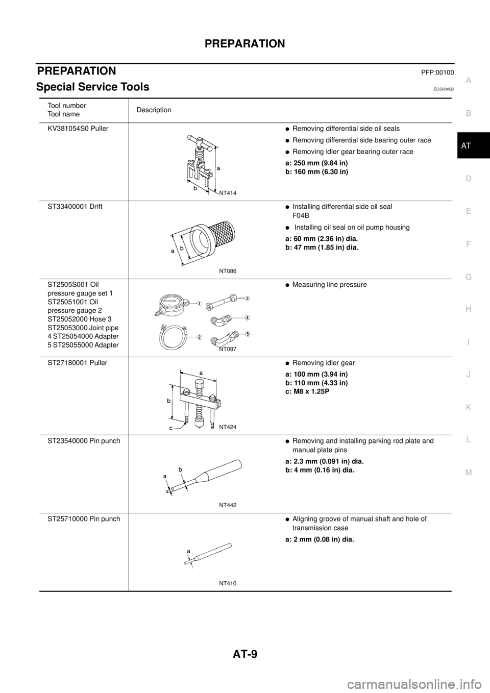
Special Service ToolsECS004Q5
Tool number
To o l n a m eDescription
KV381054S0 Puller
lRemoving differential side oil seals
lRemoving differential side bearing outer race
lRemoving idler gear bearing outer race
a: 250 mm (9.84 in)
b: 160 mm (6.30 in)
ST33400001 Drift
lInstalling differential side oil seal
F04B
lInstalling oil seal on oil pump housing
a: 60 mm (2.36 in) dia.
b: 47 mm (1.85 in) dia.
ST2505S001 Oil
pressure gauge set 1
ST25051001 Oil
pressure gauge 2
ST25052000 Hose 3
ST25053000 Joint pipe
4 ST25054000 Adapter
5 ST25055000 Adapter
lMeasuring line pressure
ST27180001 Puller
lRemoving idler gear
a: 100 mm (3.94 in)
b: 110 mm (4.33 in)
c: M8 x 1.25P
ST23540000 Pin punch
lRemoving and installing parking rod plate and
manual plate pins
a: 2.3 mm (0.091 in) dia.
b: 4 mm (0.16 in) dia.
ST25710000 Pin punch
lAligning groove of manual shaft and hole of
transmission case
a: 2 mm (0.08 in) dia.
NT414
NT086
NT097
NT424
NT442
NT410
Page 26 of 3066
AT-20
OVERALL SYSTEM
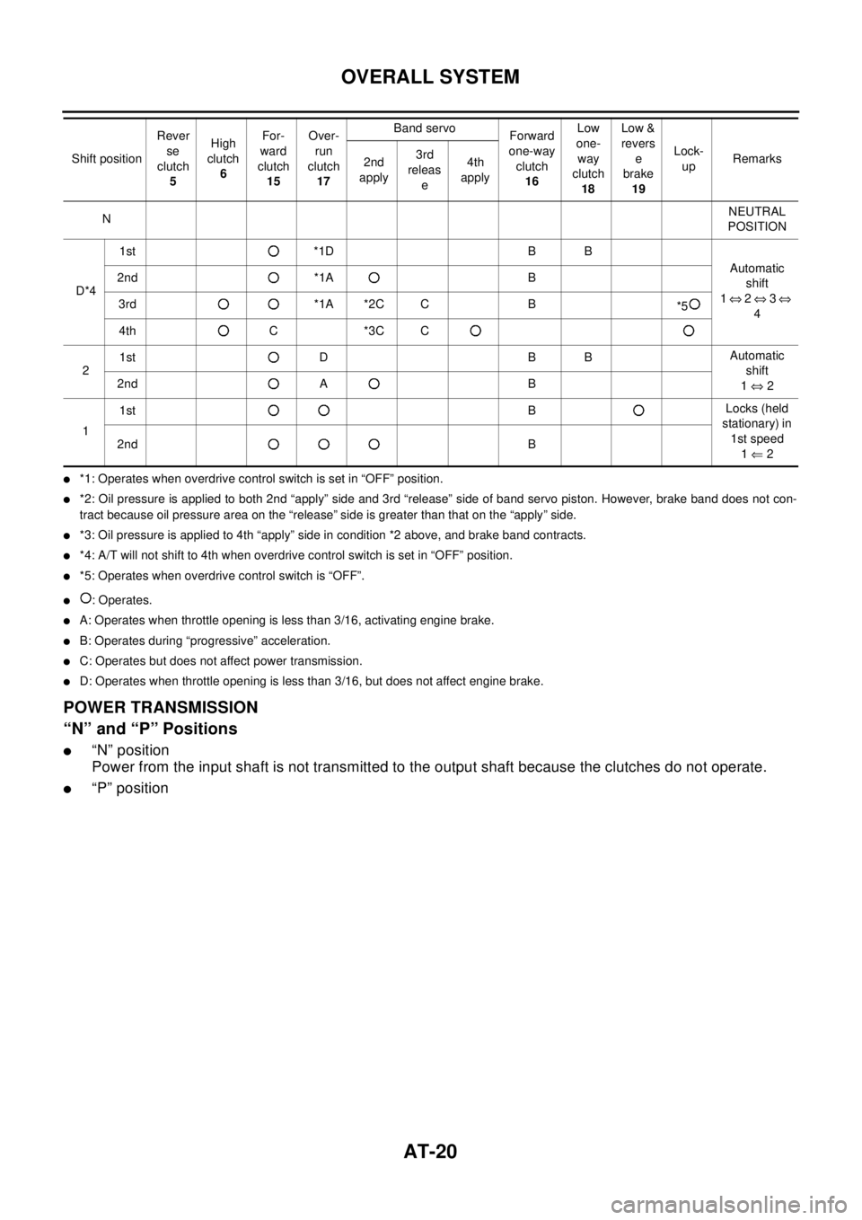
l*1: Operates when overdrive control switch is set in “OFF” position.
l*2: Oil pressure is applied to both 2nd “apply” side and 3rd “release” side of band servo piston. However, brake band does not con-
tract because oil pressure area on the “release” side is greater than that on the “apply” side.
l*3: Oil pressure is applied to 4th “apply” side in condition *2 above, and brake band contracts.
l*4: A/T will not shift to 4th when overdrive control switch is set in “OFF” position.
l*5: Operates when overdrive control switch is “OFF”.
l:Operates.
lA: Operates when throttle opening is less than 3/16, activating engine brake.
lB: Operates during “progressive” acceleration.
lC: Operates but does not affect power transmission.
lD: Operates when throttle opening is less than 3/16, but does not affect engine brake.
POWER TRANSMISSION
“N” and “P” Positions
l“N” position
Power from the input shaft is not transmitted to the output shaft because the clutches do not operate.
l“P” position
NNEUTRAL
POSITION
D*41st *1D B B
Automatic
shift
1Û2Û3Û
4 2nd *1A B
3rd *1A *2C C B
*5
4th C *3C C
21st D B BAutomatic
shift
1Û2 2nd A B
11stBLocks (held
stationary) in
1st speed
1Ü2 2ndB Shift positionRever
se
clutch
5High
clutch
6For-
ward
clutch
15Over-
run
clutch
17Band servo
Forward
one-way
clutch
16Low
one-
way
clutch
18Low &
revers
e
brake
19Lock-
upRemarks
2nd
apply3rd
releas
e4th
apply
Page 31 of 3066
OVERALL SYSTEM
AT-25
D
E
F
G
H
I
J
K
L
MA
B
AT
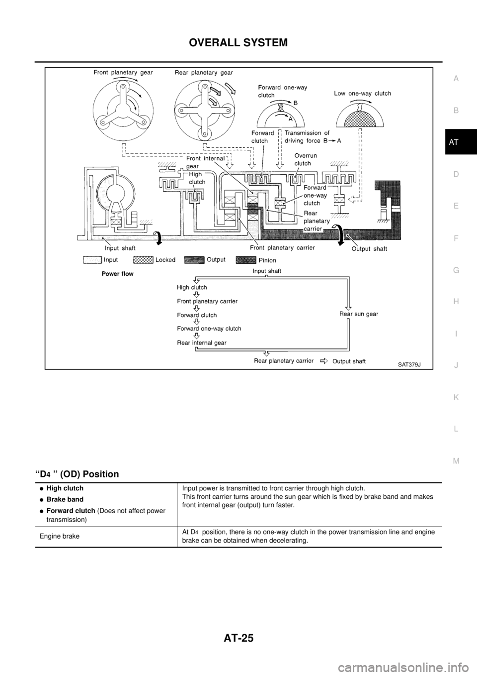
“D4” (OD) Position
SAT379J
lHigh clutch
lBrake band
lForward clutch(Does not affect power
transmission)Input power is transmitted to front carrier through high clutch.
This front carrier turns around the sun gear which is fixed by brake band and makes
front internal gear (output) turn faster.
Engine brakeAt D
4position, there is no one-way clutch in the power transmission line and engine
brake can be obtained when decelerating.
Page 32 of 3066
AT-26
OVERALL SYSTEM
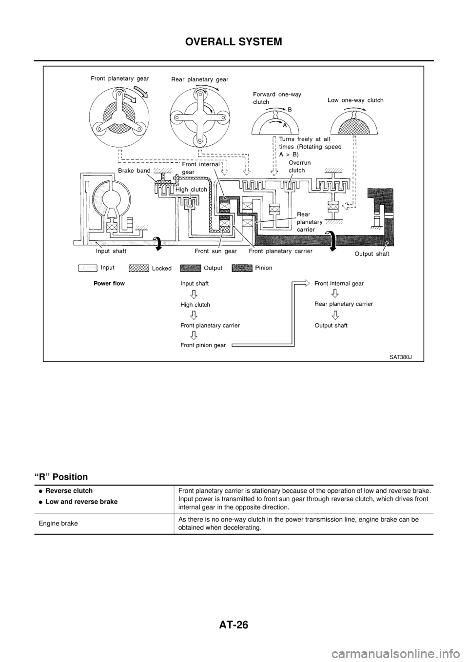
“R” Position
SAT380J
lReverse clutch
lLow and reverse brakeFront planetary carrier is stationary because of the operation of low and reverse brake.
Input power is transmitted to front sun gear through reverse clutch, which drives front
internal gear in the opposite direction.
Engine brakeAs there is no one-way clutch in the power transmission line, engine brake can be
obtained when decelerating.
Page 34 of 3066
AT-28
OVERALL SYSTEM
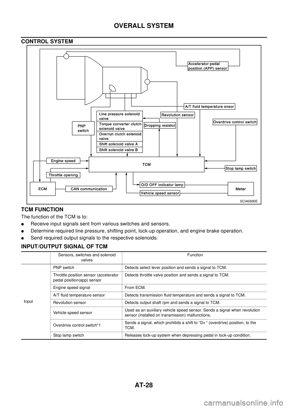
CONTROL SYSTEM
TCM FUNCTION
ThefunctionoftheTCMisto:
lReceive input signals sent from various switches and sensors.
lDetermine required line pressure, shifting point, lock-up operation, and engine brake operation.
lSend required output signals to the respective solenoids.
INPUT/OUTPUT SIGNAL OF TCM
SCIA0690E
Sensors, switches and solenoid
valvesFunction
InputPNP switch Detects select lever position and sends a signal to TCM.
Throttle position sensor (accelerator
pedal position(app) sensorDetects throttle valve position and sends a signal to TCM.
Engine speed signal From ECM.
A/T fluid temperature sensor Detects transmission fluid temperature and sends a signal to TCM.
Revolution sensor Detects output shaft rpm and sends a signal to TCM.
Vehicle speed sensorUsed as an auxiliary vehicle speed sensor. Sends a signal when revolution
sensor (installed on transmission) malfunctions.
Overdrive control switch*1Sends a signal, which prohibits a shift to “D
4” (overdrive) position, to the
TCM.
Stop lamp switch Releases lock-up system when depressing pedal in lock-up condition.
Page 36 of 3066
AT-30
OVERALL SYSTEM
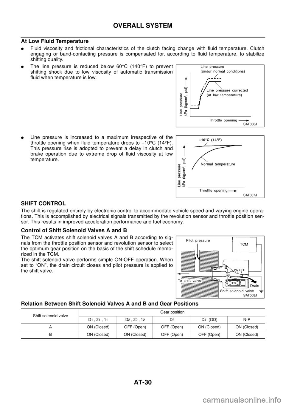
At Low Fluid Temperature
lFluid viscosity and frictional characteristics of the clutch facing change with fluid temperature. Clutch
engaging or band-contacting pressure is compensated for, according to fluid temperature, to stabilize
shifting quality.
lThe line pressure is reduced below 60°C(140°F) to prevent
shifting shock due to low viscosity of automatic transmission
fluid when temperature is low.
lLine pressure is increased to a maximum irrespective of the
throttle opening when fluid temperature drops to-10°C(14°F).
This pressure rise is adopted to prevent a delay in clutch and
brake operation due to extreme drop of fluid viscosity at low
temperature.
SHIFT CONTROL
The shift is regulated entirely by electronic control to accommodate vehicle speed and varying engine opera-
tions. This is accomplished by electrical signals transmitted by the revolution sensor and throttle position sen-
sor. This results in improved acceleration performance and fuel economy.
Control of Shift Solenoid Valves A and B
The TCM activates shift solenoid valves A and B according to sig-
nals from the throttle position sensor and revolution sensor to select
the optimum gear position on the basis of the shift schedule memo-
rizedintheTCM.
The shift solenoid valve performs simple ON-OFF operation. When
set to “ON”, the drain circuit closes and pilot pressure is applied to
the shift valve.
Relation Between Shift Solenoid Valves A and B and Gear Positions
SAT006J
SAT007J
SAT008J
Shift solenoid valveGear position
D1,21,11D2,22,12D3D4(OD) N-P
A ON (Closed) OFF (Open) OFF (Open) ON (Closed) ON (Closed)
B ON (Closed) ON (Closed) OFF (Open) OFF (Open) ON (Closed)