2003 NISSAN X-TRAIL transmission
[x] Cancel search: transmissionPage 2496 of 3066
MA-4
DESCRIPTION
DESCRIPTION
PFP:00000
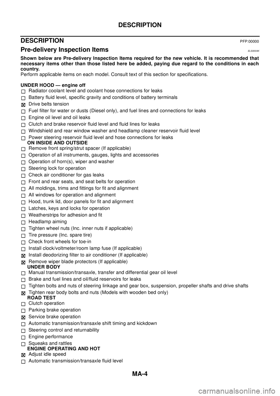
Pre-delivery Inspection ItemsELS000AK
Shown below are Pre-delivery Inspection Items required for the new vehicle. It is recommended that
necessary items other than those listed here be added, paying due regard to the conditions in each
country.
Perform applicable items on each model. Consult text of this section for specifications.
UNDER HOOD — engine off
Radiator coolant level and coolant hose connections for leaks
Battery fluid level, specific gravity and conditions of battery terminals
Drive belts tension
Fuel filter for water or dusts (Diesel only), and fuel lines and connections for leaks
Engine oil level and oil leaks
Clutch and brake reservoir fluid level and fluid lines for leaks
Windshield and rear window washer and headlamp cleaner reservoir fluid level
Power steering reservoir fluid level and hose connections for leaks
ON INSIDE AND OUTSIDE
Remove front spring/strut spacer (If applicable)
Operation of all instruments, gauges, lights and accessories
Operation of horn(s), wiper and washer
Steering lock for operation
Check air conditioner for gas leaks
Front and rear seats, and seat belts for operation
All moldings, trims and fittings for fit and alignment
All windows for operation and alignment
Hood, trunk lid, door panels for fit and alignment
Latches, keys and locks for operation
Weatherstrips for adhesion and fit
Headlamp aiming
Tighten wheel nuts (Inc. inner nuts if applicable)
Tire pressure (Inc. spare tire)
Check front wheels for toe-in
Install clock/voltmeter/room lamp fuse (If applicable)
Install deodorizing filter to air conditioner (If applicable)
Remove wiper blade protectors (If applicable)
UNDER BODY
Manual transmission/transaxle, transfer and differential gear oil level
Brake and fuel lines and oil/fluid reservoirs for leaks
Tighten bolts and nuts of steering linkage and gear box, suspension, propeller shafts and drive shafts
Tighten rear body bolts and nuts (Models with wooden bed only)
ROAD TEST
Clutch operation
Parking brake operation
Service brake operation
Automatic transmission/transaxle shift timing and kickdown
Steering control and returnability
Engine performance
Squeaks and rattles
ENGINE OPERATING AND HOT
Adjust idle speed
Automatic transmission/transaxle fluid level
Page 2509 of 3066
RECOMMENDED FLUIDS AND LUBRICANTS
MA-17
C
D
E
F
G
H
I
J
K
MA
B
MA
RECOMMENDED FLUIDS AND LUBRICANTSPFP:00000
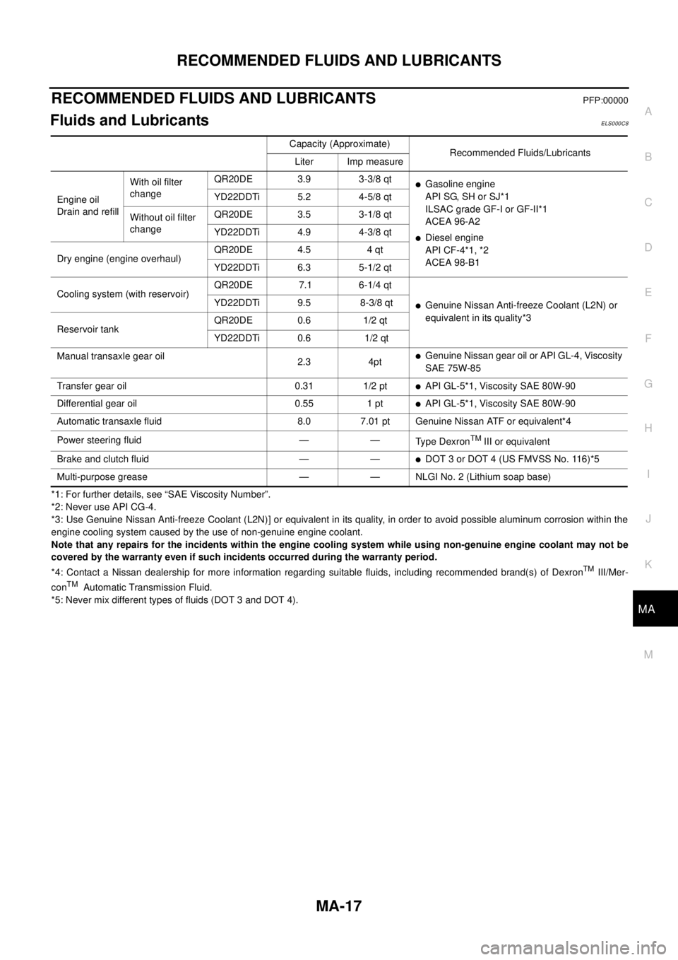
Fluids and LubricantsELS000C8
*1: For further details, see “SAE Viscosity Number”.
*2: Never use API CG-4.
*3: Use Genuine Nissan Anti-freeze Coolant (L2N)] or equivalent in its quality, in order to avoid possible aluminum corrosion within the
engine cooling system caused by the use of non-genuine engine coolant.
Note that any repairs for the incidents within the engine cooling system while using non-genuine engine coolant may not be
covered by the warranty even if such incidents occurred during the warranty period.
*4: Contact a Nissan dealership for more information regarding suitable fluids, including recommended brand(s) of Dexron
TMIII/Mer-
conTMAutomatic Transmission Fluid.
*5: Never mix different types of fluids (DOT 3 and DOT 4).Capacity (Approximate)
Recommended Fluids/Lubricants
Liter Imp measure
Engine oil
Drain and refillWith oil filter
changeQR20DE 3.9 3-3/8 qt
lGasoline engine
API SG, SH or SJ*1
ILSAC grade GF-I or GF-II*1
ACEA 96-A2
lDiesel engine
API CF-4*1, *2
ACEA 98-B1 YD22DDTi 5.2 4-5/8 qt
Without oil filter
changeQR20DE 3.5 3-1/8 qt
YD22DDTi 4.9 4-3/8 qt
Dry engine (engine overhaul)QR20DE 4.5 4 qt
YD22DDTi 6.3 5-1/2 qt
Cooling system (with reservoir)QR20DE 7.1 6-1/4 qt
lGenuine Nissan Anti-freeze Coolant (L2N) or
equivalent in its quality*3 YD22DDTi 9.5 8-3/8 qt
Reservoir tankQR20DE 0.6 1/2 qt
YD22DDTi 0.6 1/2 qt
Manual transaxle gear oil
2.3 4pt
lGenuine Nissan gear oil or API GL-4, Viscosity
SAE 75W-85
Transfer gear oil 0.31 1/2 pt
lAPI GL-5*1, Viscosity SAE 80W-90
Differential gear oil 0.55 1 pt
lAPI GL-5*1, Viscosity SAE 80W-90
Automatic transaxle fluid 8.0 7.01 pt Genuine Nissan ATF or equivalent*4
Power steering fluid — —
Ty p e D e x r o n
TMIII or equivalent
Brake and clutch fluid — —
lDOT 3 or DOT 4 (US FMVSS No. 116)*5
Multi-purpose grease — — NLGI No. 2 (Lithium soap base)
Page 2537 of 3066
MT-1
MANUAL TRANSAXLE
C TRANSMISSION/TRANSAXLE
CONTENTS
D
E
F
G
H
I
J
K
L
M
SECTION
A
B
MT
MANUAL TRANSAXLE
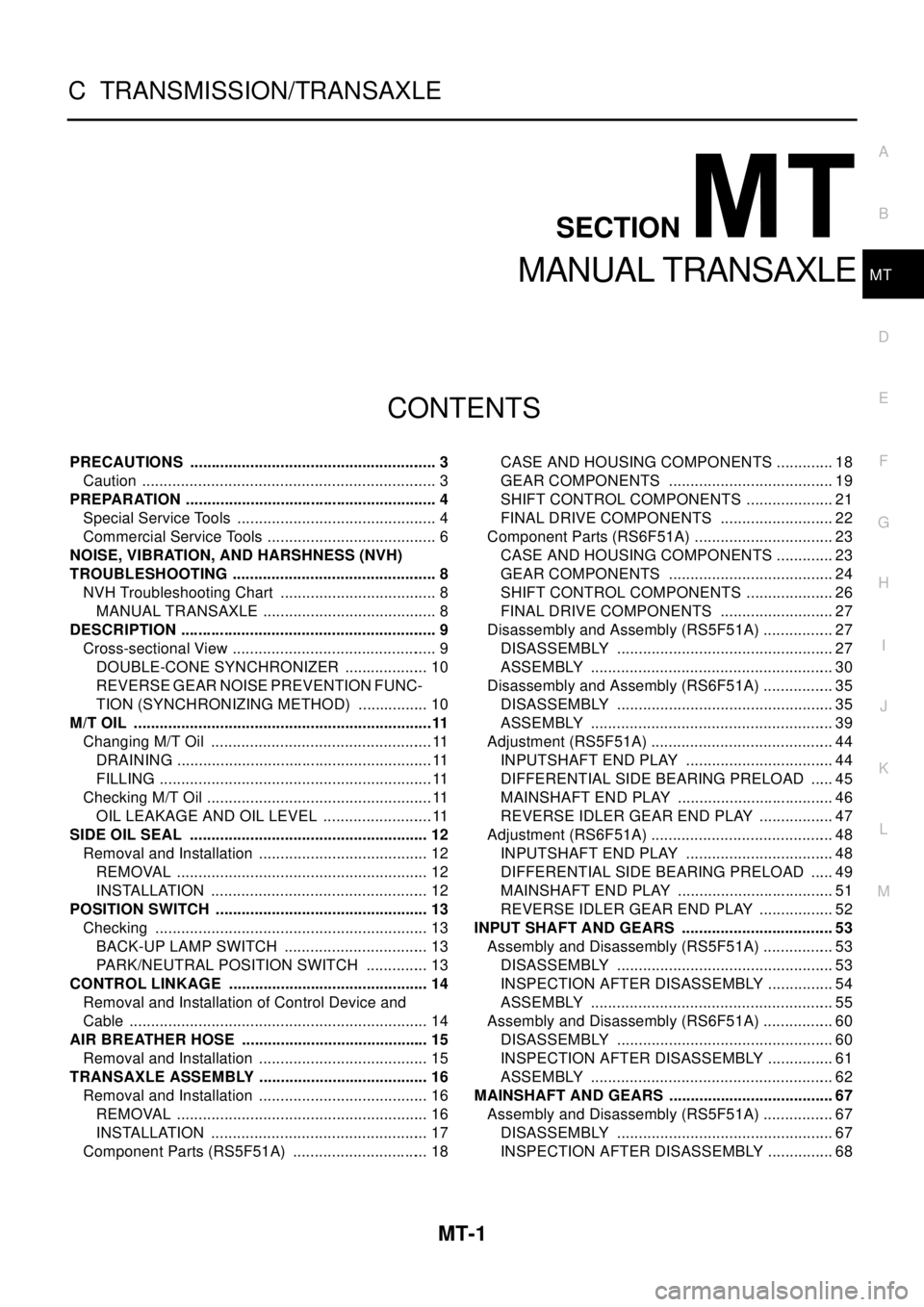
PRECAUTIONS .......................................................... 3
Caution ..................................................................... 3
PREPARATION ........................................................... 4
Special Service Tools ............................................... 4
Commercial Service Tools ........................................ 6
NOISE, VIBRATION, AND HARSHNESS (NVH)
TROUBLESHOOTING ................................................ 8
NVH Troubleshooting Chart ..................................... 8
MANUAL TRANSAXLE ......................................... 8
DESCRIPTION ............................................................ 9
Cross-sectional View ................................................ 9
DOUBLE-CONE SYNCHRONIZER .................... 10
REVERSE GEAR NOISE PREVENTION FUNC-
TION (SYNCHRONIZING METHOD) ................. 10
M/T OIL ......................................................................11
Changing M/T Oil ....................................................11
DRAINING ............................................................11
FILLING ................................................................11
Checking M/T Oil .....................................................11
OIL LEAKAGE AND OIL LEVEL ..........................11
SIDE OIL SEAL ........................................................ 12
Removal and Installation ........................................ 12
REMOVAL ........................................................... 12
INSTALLATION ................................................... 12
POSITION SWITCH .................................................. 13
Checking ................................................................ 13
BACK-UP LAMP SWITCH .................................. 13
PARK/NEUTRAL POSITION SWITCH ............... 13
CONTROL LINKAGE ............................................... 14
Removal and Installation of Control Device and
Cable ...................................................................... 14
AIR BREATHER HOSE ............................................ 15
Removal and Installation ........................................ 15
TRANSAXLE ASSEMBLY ........................................ 16
Removal and Installation ........................................ 16
REMOVAL ........................................................... 16
INSTALLATION ................................................... 17
Component Parts (RS5F51A) ................................ 18CASE AND HOUSING COMPONENTS .............. 18
GEAR COMPONENTS ....................................... 19
SHIFT CONTROL COMPONENTS ..................... 21
FINAL DRIVE COMPONENTS ........................... 22
Component Parts (RS6F51A) ................................. 23
CASE AND HOUSING COMPONENTS .............. 23
GEAR COMPONENTS ....................................... 24
SHIFT CONTROL COMPONENTS ..................... 26
FINAL DRIVE COMPONENTS ........................... 27
Disassembly and Assembly (RS5F51A) ................. 27
DISASSEMBLY ................................................... 27
ASSEMBLY ......................................................... 30
Disassembly and Assembly (RS6F51A) ................. 35
DISASSEMBLY ................................................... 35
ASSEMBLY ......................................................... 39
Adjustment (RS5F51A) ........................................... 44
INPUTSHAFT END PLAY ................................... 44
DIFFERENTIAL SIDE BEARING PRELOAD ...... 45
MAINSHAFT END PLAY ..................................... 46
REVERSE IDLER GEAR END PLAY .................. 47
Adjustment (RS6F51A) ........................................... 48
INPUTSHAFT END PLAY ................................... 48
DIFFERENTIAL SIDE BEARING PRELOAD ...... 49
MAINSHAFT END PLAY ..................................... 51
REVERSE IDLER GEAR END PLAY .................. 52
INPUT SHAFT AND GEARS .................................... 53
Assembly and Disassembly (RS5F51A) ................. 53
DISASSEMBLY ................................................... 53
INSPECTION AFTER DISASSEMBLY ................ 54
ASSEMBLY ......................................................... 55
Assembly and Disassembly (RS6F51A) ................. 60
DISASSEMBLY ................................................... 60
INSPECTION AFTER DISASSEMBLY ................ 61
ASSEMBLY ......................................................... 62
MAINSHAFT AND GEARS ....................................... 67
Assembly and Disassembly (RS5F51A) ................. 67
DISASSEMBLY ................................................... 67
INSPECTION AFTER DISASSEMBLY ................ 68
Page 2865 of 3066
REAR SUSPENSION MEMBER
RSU-13
C
D
F
G
H
I
J
K
L
MA
B
RSU
REAR SUSPENSION MEMBERPFP:55501
Removal and InstallationEES0007M
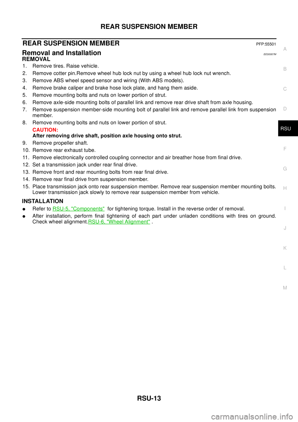
REMOVAL
1. Remove tires. Raise vehicle.
2. Remove cotter pin.Remove wheel hub lock nut by using a wheel hub lock nut wrench.
3. Remove ABS wheel speed sensor and wiring (With ABS models).
4. Remove brake caliper and brake hose lock plate, and hang them aside.
5. Remove mounting bolts and nuts on lower portion of strut.
6. Remove axle-side mounting bolts of parallel link and remove rear drive shaft from axle housing.
7. Remove suspension member-side mounting bolt of parallel link and remove parallel link from suspension
member.
8. Remove mounting bolts and nuts on lower portion of strut.
CAUTION:
After removing drive shaft, position axle housing onto strut.
9. Remove propeller shaft.
10. Remove rear exhaust tube.
11. Remove electronically controlled coupling connector and air breather hose from final drive.
12. Set a transmission jack under rear final drive.
13. Remove front and rear mounting bolts from rear final drive.
14. Remove rear final drive from suspension member.
15. Place transmission jack onto rear suspension member. Remove rear suspension member mounting bolts.
Lower transmission jack slowly to remove rear suspension member from vehicle.
INSTALLATION
lRefer toRSU-5, "Components"for tightening torque. Install in the reverse order of removal.
lAfter installation, perform final tightening of each part under unladen conditions with tires on ground.
Check wheel alignment.RSU-6, "
Wheel Alignment".
Page 2982 of 3066
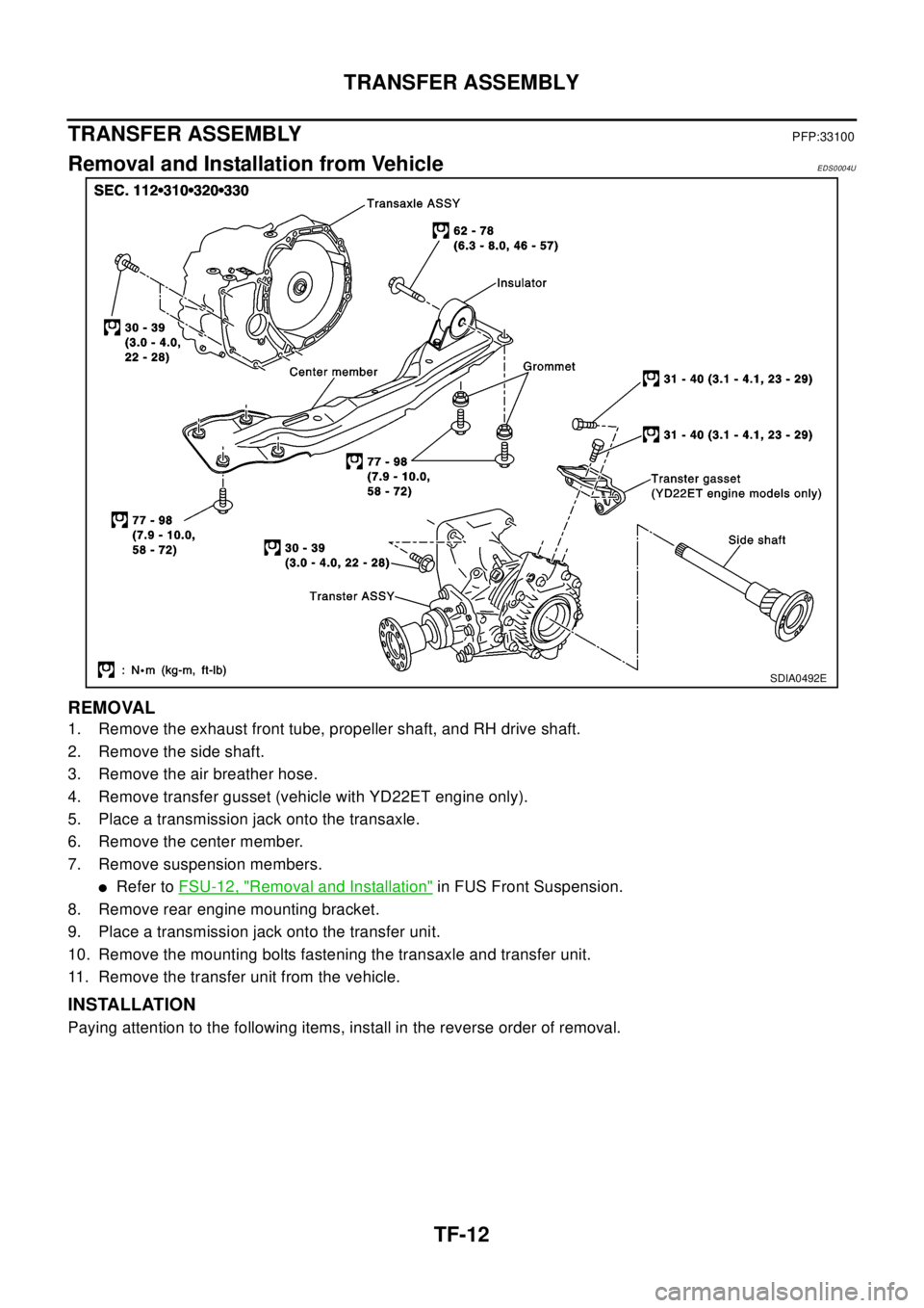
TF-12
TRANSFER ASSEMBLY
TRANSFER ASSEMBLY
PFP:33100
Removal and Installation from VehicleEDS0004U
REMOVAL
1. Remove the exhaust front tube, propeller shaft, and RH drive shaft.
2. Remove the side shaft.
3. Remove the air breather hose.
4. Remove transfer gusset (vehicle with YD22ET engine only).
5. Place a transmission jack onto the transaxle.
6. Remove the center member.
7. Remove suspension members.
lRefer toFSU-12, "Removal and Installation"in FUS Front Suspension.
8. Remove rear engine mounting bracket.
9. Place a transmission jack onto the transfer unit.
10. Remove the mounting bolts fastening the transaxle and transfer unit.
11. Remove the transfer unit from the vehicle.
INSTALLATION
Paying attention to the following items, install in the reverse order of removal.
SDIA0492E
Page 3003 of 3066
ALL MODE 4X4 SYSTEM
TF-33
C
E
F
G
H
I
J
K
L
MA
B
TF
FAIL- SAFE FUNCTION
lIf a malfunction occurs in 4WD electrical system, and control unit detects the malfunction, 4WD warning
lamp on gauge turns ON to inform driver of system malfunction.
lWhen 4WD warning lamp is ON, vehicle is in 2WD.
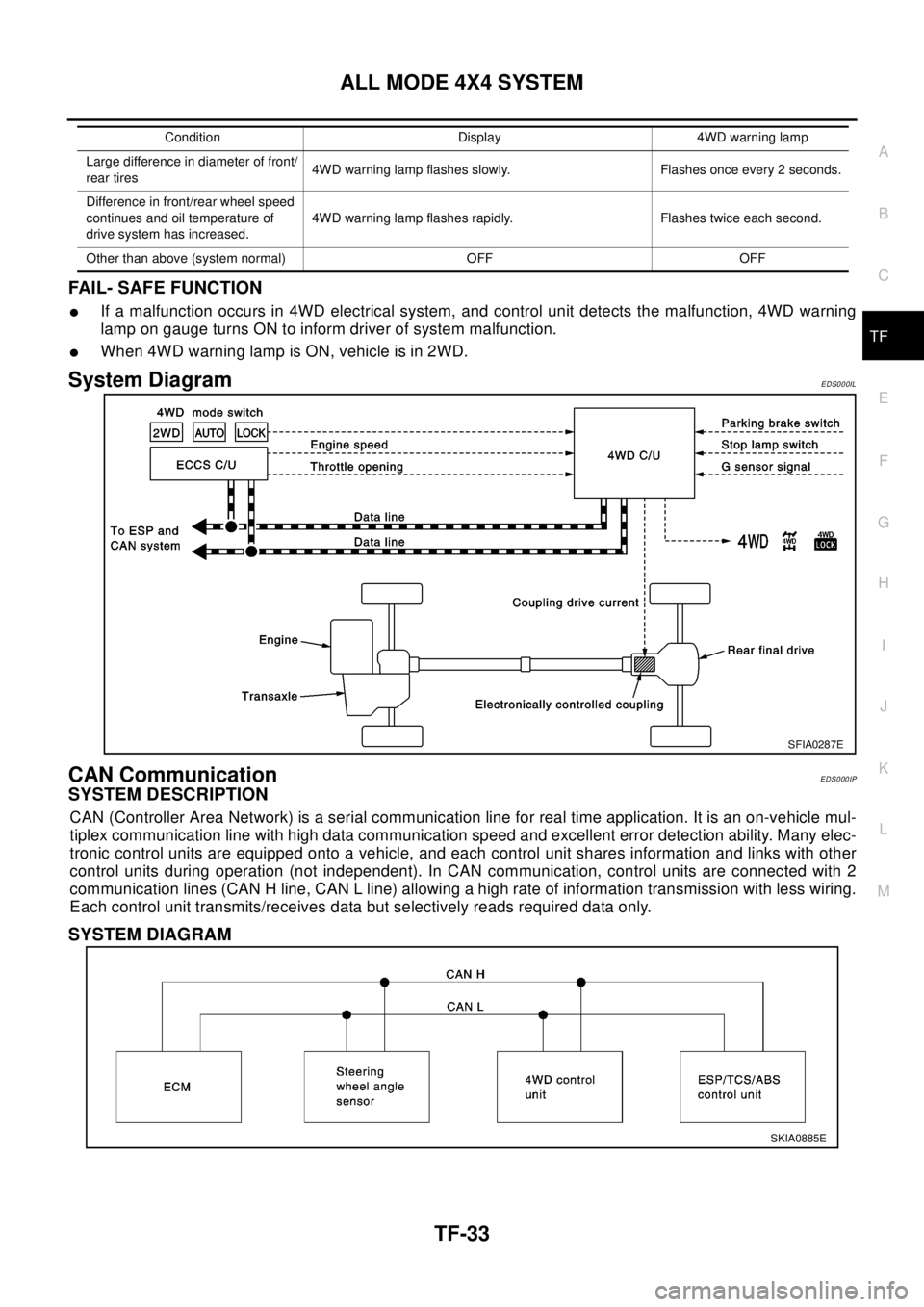
System DiagramEDS000IL
CAN CommunicationEDS000IP
SYSTEM DESCRIPTION
CAN (Controller Area Network) is a serial communication line for real time application. It is an on-vehicle mul-
tiplex communication line with high data communication speed and excellent error detection ability. Many elec-
tronic control units are equipped onto a vehicle, and each control unit shares information and links with other
control units during operation (not independent). In CAN communication, control units are connected with 2
communication lines (CAN H line, CAN L line) allowing a high rate of information transmission with less wiring.
Each control unit transmits/receives data but selectively reads required data only.
SYSTEM DIAGRAM
Largedifferenceindiameteroffront/
rear tires4WD warning lamp flashes slowly. Flashes once every 2 seconds.
Difference in front/rear wheel speed
continues and oil temperature of
drive system has increased.4WD warning lamp flashes rapidly. Flashes twice each second.
Other than above (system normal) OFF OFFCondition Display 4WD warning lamp
SFIA0287E
SKIA0885E