2003 NISSAN X-TRAIL tire type
[x] Cancel search: tire typePage 872 of 3066
![NISSAN X-TRAIL 2003 Electronic Repair Manual BRC-4
[4WD/ABS]
PRECAUTIONS
[4WD/ABS]PRECAUTIONSPFP:00001
Precautions for brake systemEFS001B6
lRecommended fluid is brake fluid “DOT 3 ”or “DOT 4”.
lNever reuse drained brake fluid.
lBe caref NISSAN X-TRAIL 2003 Electronic Repair Manual BRC-4
[4WD/ABS]
PRECAUTIONS
[4WD/ABS]PRECAUTIONSPFP:00001
Precautions for brake systemEFS001B6
lRecommended fluid is brake fluid “DOT 3 ”or “DOT 4”.
lNever reuse drained brake fluid.
lBe caref](/manual-img/5/57402/w960_57402-871.png)
BRC-4
[4WD/ABS]
PRECAUTIONS
[4WD/ABS]PRECAUTIONSPFP:00001
Precautions for brake systemEFS001B6
lRecommended fluid is brake fluid “DOT 3 ”or “DOT 4”.
lNever reuse drained brake fluid.
lBe careful not to splash brake fluid on painted areas.
lTo clean or wash all parts of master cylinder, disc brake caliper and wheel cylinder, use clean brake fluid.
lNever use mineral oils such as gasoline or kerosene. They will ruin rubber parts of the hydraulic system.
lUse flare nut wrench when removing and installing brake tube.
lAlways torque brake lines when installing.
lBurnish the brake contact surfaces after refinishing or replacing
drums or rotors, after replacing pads or linings, or if a soft pedal
occurs at very low mileage. Refer toBR-10, "
Brake Burnishing
Procedure".
lBefore working, turn OFF ignition switch. Disconnect connectors
for ABS actuator and control module or battery terminals.
WAR NIN G:
lClean brake pads and shoes with a waste cloth, then wipe
with a dust collector.
Precautions for brake controlEFS001B7
lIf malfunction is indicated by 4WD warning lamp and/or ABS warning lamp, collect necessary information
from customer (what symptoms are present under what conditions). Find out possible causes before start-
ing service. Besides electrical system inspection, check operation of ABS actuator.
lIf malfunction is detected, proceed to trouble diagnosis after checking tire pressure and tire wear.
lStopping distance or steering stability may be deteriorated by the following conditions. Tire size and type
are in improper combination. Brake pads are not Nissan genuine parts.
lFitting tires of different size on vehicle can be cause of longitudinal vibration. Always use tires of the same
size and brand. Exchange front and rear tires on the following conditions: Longitudinal vibration occurs in
vehicle with tires of the same size and brand. After replacement, perform trouble diagnosis. 1580|None
l4WD/ABS function may have a failure or error under following condition: There is radio, antenna, or
antenna lead-in wire (including wiring) near control module.
lIf aftermarket parts (e.g. Car stereo equipment, CD player) have been installed, check electrical har-
nesses for pinches, open, and improper wiring.
SBR686C
Page 920 of 3066
![NISSAN X-TRAIL 2003 Electronic Repair Manual BRC-52
[ESP/TCS/ABS]
PRECAUTIONS
[ESP/TCS/ABS]PRECAUTIONSPFP:00001
Precautions for Supplemental Restraint System (SRS) “AIR BAG” and “SEAT
BELT PRE-TENSIONER”
EFS0019N
The Supplemental Restrai NISSAN X-TRAIL 2003 Electronic Repair Manual BRC-52
[ESP/TCS/ABS]
PRECAUTIONS
[ESP/TCS/ABS]PRECAUTIONSPFP:00001
Precautions for Supplemental Restraint System (SRS) “AIR BAG” and “SEAT
BELT PRE-TENSIONER”
EFS0019N
The Supplemental Restrai](/manual-img/5/57402/w960_57402-919.png)
BRC-52
[ESP/TCS/ABS]
PRECAUTIONS
[ESP/TCS/ABS]PRECAUTIONSPFP:00001
Precautions for Supplemental Restraint System (SRS) “AIR BAG” and “SEAT
BELT PRE-TENSIONER”
EFS0019N
The Supplemental Restraint System such as “AIR BAG” and “SEAT BELT PRE-TENSIONER”, used along
with a front seat belt, helps to reduce the risk or severity of injury to the driver and front passenger for certain
types of collision. Information necessary to service the system safely is included in the SRS and SB section of
this Service Manual.
WAR NIN G:
lTo avoid rendering the SRS inoperative, which could increase the risk of personal injury or death
in the event of a collision which would result in air bag inflation, all maintenance must be per-
formed by an authorized NISSAN/INFINITI dealer.
lImproper maintenance, including incorrect removal and installation of the SRS, can lead to per-
sonal injury caused by unintentional activation of the system. For removal of Spiral Cable and Air
Bag Module, see the SRS section.
lDo not use electrical test equipment on any circuit related to the SRS unless instructed to in this
Service Manual. SRS wiring harnesses can be identified by yellow harness connector.
Precautions for Brake SystemEFS0019O
lRecommended fluid is brake fluid “DOT 3” or “DOT 4”.
lNever reuse drained brake fluid.
lBe careful not to splash brake fluid on painted areas; it may cause paint damage. If brake fluid is splashed
on painted areas, wash it away with water immediately.
lNever use mineral oils such as gasoline or kerosene. They will ruin rubber parts of hydraulic system.
lUse flare nut wrench when removing and installing brake tubes.
lAlways torque brake lines when installing.
lBefore working, turn the ignition switch OFF and disconnect the
connectors for the ESP/TCS/ABS actuator and control unit or
the battery terminals.
lBurnish the brake contact surfaces after refinishing or replacing
drums or rotors, after replacing pads or linings, or if a soft pedal
occurs at very low mileage. Refer toBR-10, "
Brake Burnishing
Procedure".
WAR NIN G:
Clean brakes with a vacuum dust collector to minimize risk
of health hazard from powder caused by friction.
Precautions for Brake ControlEFS0019P
lDuring the EPS/TCS/ABS operation, the brake pedal vibrates lightly and its mechanical noise may be
heard. This is a normal condition.
lJust after starting the vehicle after ignition switch ON, the brake pedal may vibrate or the motor operating
noise may be heard from the engine compartment. This is a normal status of the operation check.
lThe stopping distance may be longer than that of vehicles without ABS when the vehicle drives on rough,
gravel, or snowy (fresh deep snow) road.
lIf a malfunction is indicated by the ABS warning lamp, or other warning lamps, collect the necessary infor-
mation from the customer (what symptoms are present under what conditions) and find out the possible
causes before starting the service. Besides the electrical system inspection, check the booster operation,
brake fluid level, and oil leaks.
lIf the tire size and type are used in a improper combination, or the brake pads are not NISSAN genuine
parts, the stopping distance or steering stability may deteriorate.
lIf there is a radio, antenna, or antenna lead-in wire (including wiring) near the control unit, the ESP/TCS/
ABS function may have a malfunction or error.
lIf aftermarket parts (e.g. Car stereo equipment, CD player) have been installed, check the electrical har-
nesses for pinches, open, and improper wiring.
SBR686C
Page 2252 of 3066
SERVICE DATA AND SPECIFICATIONS (SDS)
FSU-13
C
D
F
G
H
I
J
K
L
MA
B
FSU
SERVICE DATA AND SPECIFICATIONS (SDS)PFP:00030
General SpecificationEES000J6
Wheel Alignment (Unladen)EES00079
: Fuel, radiator coolant and engine oil full. Spare tire, jack, hand tools and mats in designated positions.
Ball JointEES0007A
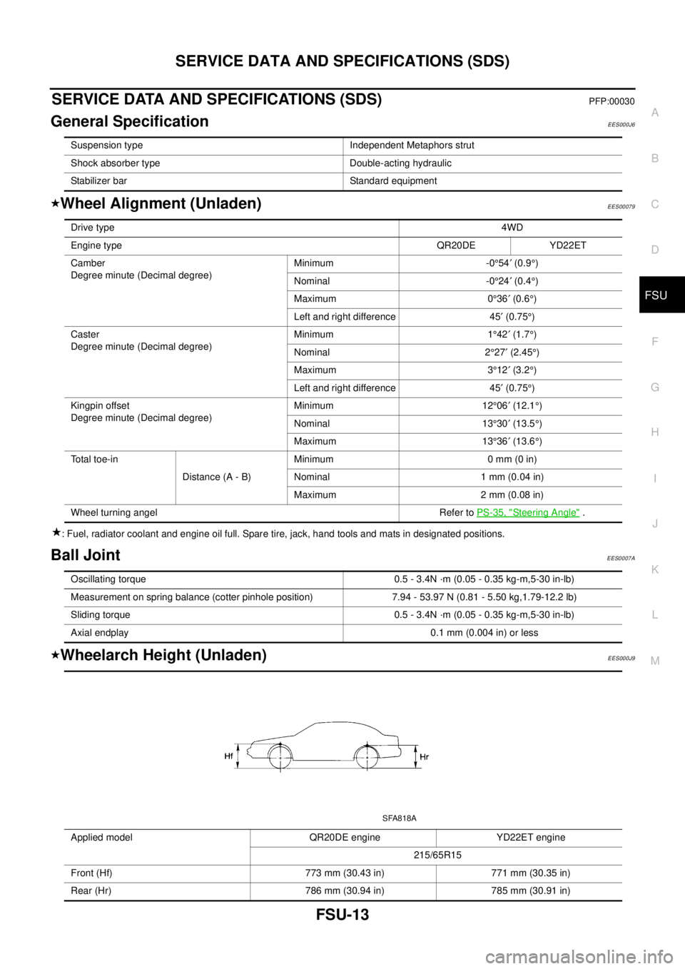
Wheelarch Height (Unladen)EES000J9
Suspension type Independent Metaphors strut
Shock absorber type Double-acting hydraulic
Stabilizer bar Standard equipment
Drive type4WD
Engine typeQR20DE YD22ET
Camber
Degree minute (Decimal degree)Minimum -0°54¢(0.9°)
Nominal -0°24¢(0.4°)
Maximum 0°36¢(0.6°)
Left and right difference 45¢(0.75°)
Caster
Degree minute (Decimal degree)Minimum 1°42¢(1.7°)
Nominal 2°27¢(2.45°)
Maximum 3°12¢(3.2°)
Left and right difference 45¢(0.75°)
Kingpin offset
Degree minute (Decimal degree)Minimum 12°06¢(12.1°)
Nominal 13°30¢(13.5°)
Maximum 13°36¢(13.6°)
To t a l t o e - i n
Distance (A - B)Minimum 0 mm (0 in)
Nominal 1 mm (0.04 in)
Maximum 2 mm (0.08 in)
Wheel turning angel Refer toPS-35, "
Steering Angle".
Oscillating torque 0.5 - 3.4N ·m (0.05 - 0.35 kg-m,5-30 in-lb)
Measurement on spring balance (cotter pinhole position) 7.94 - 53.97 N (0.81 - 5.50 kg,1.79-12.2 lb)
Sliding torque 0.5 - 3.4N ·m (0.05 - 0.35 kg-m,5-30 in-lb)
Axial endplay 0.1 mm (0.004 in) or less
Applied model QR20DE engine YD22ET engine
215/65R15
Front (Hf) 773 mm (30.43 in) 771 mm (30.35 in)
Rear (Hr) 786 mm (30.94 in) 785 mm (30.91 in)
SFA818A
Page 2530 of 3066
MA-38
CHASSIS AND BODY MAINTENANCE
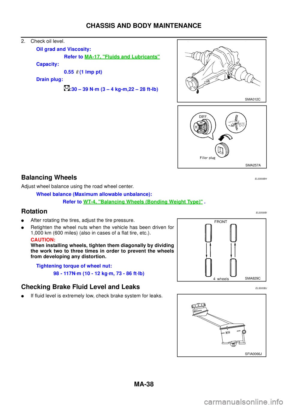
2. Check oil level.
Balancing WheelsELS000BH
Adjust wheel balance using the road wheel center.
RotationELS000BI
lAfter rotating the tires, adjust the tire pressure.
lRetighten the wheel nuts when the vehicle has been driven for
1,000 km (600 miles) (also in cases of a flat tire, etc.).
CAUTION:
When installing wheels, tighten them diagonally by dividing
the work two to three times in order to prevent the wheels
from developing any distortion.
Checking Brake Fluid Level and LeaksELS000BJ
lIf fluid level is extremely low, check brake system for leaks.Oil grad and Viscosity:
Refer toMA-17, "
Fluids and Lubricants"
Capacity:
0.55 (1 lmp pt)
Drain plug:
:30–39N·m(3–4kg-m,22–28ft-lb)
SMA012C
SMA257A
Wheel balance (Maximum allowable unbalance):
Refer toWT-4, "
Balancing Wheels (Bonding Weight Type)".
Tightening torque of wheel nut:
98 - 117N·m (10 - 12 kg·m, 73 - 86 ft·lb)
SMA829C
SFIA0066J
Page 2866 of 3066
RSU-14
SERVICE DATA AND SPECIFICATIONS (SDS)
SERVICE DATA AND SPECIFICATIONS (SDS)
PFP:00030
General SpecificationEES000J7
Wheel Alignment (Unladen)EES0007N
: Fuel, radiator coolant and engine oil full. Spare tire, jack, hand tools and mats in designated positions.
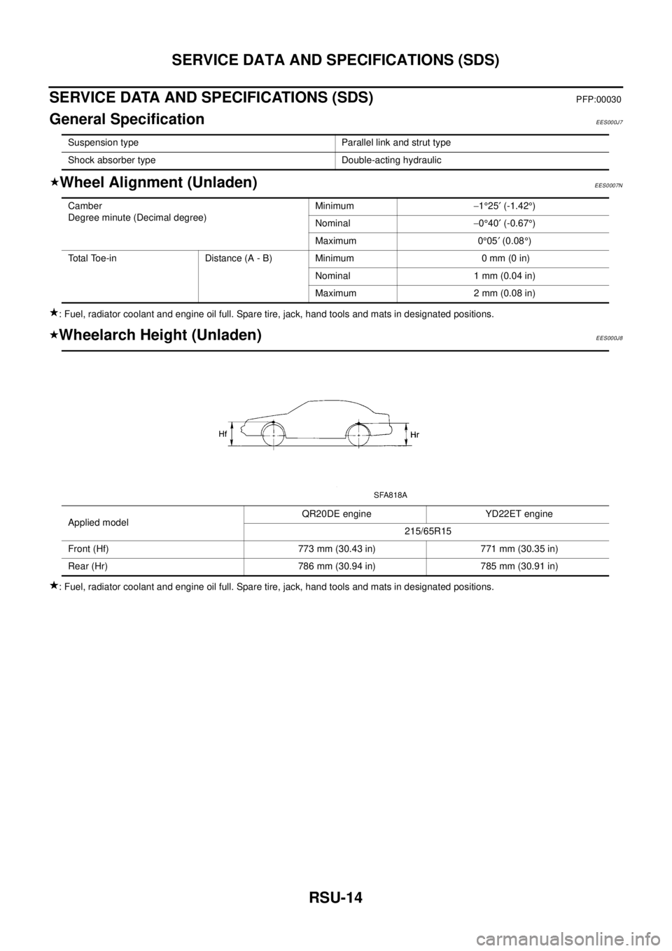
Wheelarch Height (Unladen)EES000J8
: Fuel, radiator coolant and engine oil full. Spare tire, jack, hand tools and mats in designated positions.Suspension type Parallel link and strut type
Shock absorber type Double-acting hydraulic
Camber
Degree minute (Decimal degree)Minimum-1°25¢(-1.42°)
Nominal-0°40¢(-0.67°)
Maximum 0°05¢(0.08°)
Total Toe-in Distance (A - B) Minimum 0 mm (0 in)
Nominal 1 mm (0.04 in)
Maximum 2 mm (0.08 in)
Applied modelQR20DE engine YD22ET engine
215/65R15
Front (Hf) 773 mm (30.43 in) 771 mm (30.35 in)
Rear (Hr) 786 mm (30.94 in) 785 mm (30.91 in)
SFA818A
Page 2925 of 3066
PRECAUTIONS
SRS-3
C
D
E
F
G
I
J
K
L
MA
B
SRS
PRECAUTIONSPFP:00001
Supplemental Restraint System (SRS) “AIR BAG” and “SEAT BELT PRE-TEN-
SIONER”
EHS000BG
The Supplemental Restraint System such as “AIR BAG” and “SEAT BELT PRE-TENSIONER” used along with
a front seat belt, helps to reduce the risk or severity of injury to the driver and front passenger for certain types
of collision.
WA RN ING:
lTo avoid rendering the SRS inoperative, which could increase the risk of personal injury or death
in the event of a collision which would result in air bag inflation, all maintenance should be per-
formed by an authorized NISSAN/INFINITI dealer.
lImproper maintenance, including incorrect removal and installation of the SRS, can lead to per-
sonal injury caused by unintentional activation of the system.
lDo not use electrical test equipment on any circuit related to the SRS unless instructed to in this
Service Manual. SRS wiring harnesses can be identified by yellow harness connector.
Precautions for SRS “AIR BAG” and “SEAT BELT PRE-TENSIONER” ServiceEHS000BH
lDo not use electrical test equipment to check SRS circuits unless instructed to in this Service Manual.
lBefore servicing the SRS, turn ignition switch “OFF”, disconnect battery ground cable and wait at least 3
minutes.
For approximately 3 minutes after the cables is removed, it is still possible for the air bag and seat belt
pre-tensioner to deploy. Therefore, do not work on any SRS connectors or wires until at least 3 minutes
have passed.
lDiagnosis sensor unit must always be installed with their arrow marks “Ü” pointing towards the front of the
vehicle for proper operation. Also check diagnosis sensor unit for cracks, deformities or rust before instal-
lation and replace as required.
lThe spiral cable must be aligned with the neutral position since its rotations are limited. Do not attempt to
turn steering wheel or column after removal of steering gear.
lHandle air bag module carefully. Always place driver and front passenger air bag modules with the pad
side facing upward and place front side air bag module standing with stud bolt side setting bottom.
lConduct self-diagnosis to check entire SRS for proper function after replacing any components.
lAfter air bag inflates, the front instrument panel assembly should be replaced if damaged.
Trouble Diagnosis PrecautionEHS000BI
Whenyoureadwiringdiagrams,refertothefollowings:
l“HOW TO READ WIRING DIAGRAMS” in GI section
lPG-2, "POWER SUPPLY ROUTING"in PG section
When you perform trouble diagnosis, refer to the followings:
l“HOW TO FOLLOW TEST GROUP IN TROUBLE DIAGNOSIS” in GI section
l“HOW TO PERFORM EFFICIENT DIAGNOSIS FOR AN ELECTRICAL INCIDENT” in GI section
Check for any service bulletins before servicing the vehicle.
Page 3033 of 3066

WT-1
ROAD WHEELS & TIRES
E SUSPENSION
CONTENTS
C
D
F
G
H
I
J
K
L
M
SECTION
A
B
WT
ROAD WHEELS & TIRES
NOISE, VIBRATION, AND HARSHNESS (NVH)
TROUBLESHOOTING ................................................ 2
NVH Troubleshooting Chart ..................................... 2
ROAD WHEEL ............................................................ 3
Inspection ................................................................. 3
ALUMINUM WHEEL ............................................. 3
STEEL WHEEL ..................................................... 3ROAD WHEEL TIRE ASSEMBLY .............................. 4
Balancing Wheels (Bonding Weight Type) ............... 4
REMOVAL ............................................................. 4
WHEEL BALANCE ADJUSTMENT ....................... 4
Rotation .................................................................... 4
SERVICE DATA AND SPECIFICATIONS (SDS) ........ 5
Road Wheel .............................................................. 5
Page 3036 of 3066
WT-4
ROAD WHEEL TIRE ASSEMBLY
ROAD WHEEL TIRE ASSEMBLY
PFP:40300
Balancing Wheels (Bonding Weight Type)EES000J5
REMOVAL
1. Remove inner and outer balance weights from the road wheel.
CAUTION:
Be careful not to scratch the road wheel during removal procedures.
2. Using releasing agent, remove double-faced adhesive tape from the road wheel.
CAUTION:
Be careful not to scratch the road wheel during removal.
lAfter removing double-faced adhesive tape, wipe clean traces of releasing agent from the road wheel.
WHEEL BALANCE ADJUSTMENT
lIf a tire balance machine has adhesion balance weight mode settings and drive-in weight mode setting,
select and adjust a drive-in weight mode suitable for road wheels.
1. Set road wheel on wheel balancer using the center hole as a guide. Start the tire balance machine.
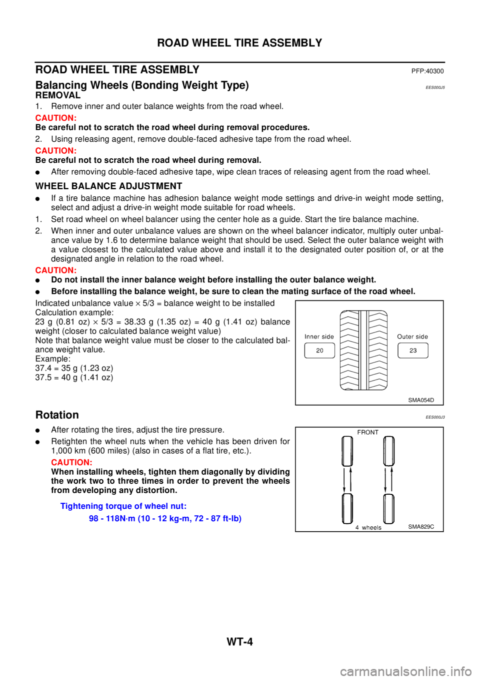
2. When inner and outer unbalance values are shown on the wheel balancer indicator, multiply outer unbal-
ance value by 1.6 to determine balance weight that should be used. Select the outer balance weight with
a value closest to the calculated value above and install it to the designated outer position of, or at the
designated angle in relation to the road wheel.
CAUTION:
lDo not install the inner balance weight before installing the outer balance weight.
lBefore installing the balance weight, be sure to clean the mating surface of the road wheel.
Indicated unbalance value´5/3 = balance weight to be installed
Calculation example:
23 g (0.81 oz)´5/3 = 38.33 g (1.35 oz) = 40 g (1.41 oz) balance
weight (closer to calculated balance weight value)
Note that balance weight value must be closer to the calculated bal-
ance weight value.
Example:
37.4=35g(1.23oz)
37.5=40g(1.41oz)
RotationEES000J3
lAfter rotating the tires, adjust the tire pressure.
lRetighten the wheel nuts when the vehicle has been driven for
1,000 km (600 miles) (also in cases of a flat tire, etc.).
CAUTION:
When installing wheels, tighten them diagonally by dividing
the work two to three times in order to prevent the wheels
from developing any distortion.
SMA054D
Tightening torque of wheel nut:
98 - 118N·m (10 - 12 kg-m, 72 - 87 ft-lb)
SMA829C