2003 NISSAN X-TRAIL oil
[x] Cancel search: oilPage 10 of 3066

AT-4
Differential Side Oil Seal Replacement .................457
Revolution Sensor Replacement ..........................457
REMOVAL AND INSTALLATION ...........................458
Removal ...............................................................458
Installation .............................................................459
OVERHAUL .............................................................461
Components .........................................................461
Oil Channel ...........................................................464
Locations of Adjusting Shims, Needle Bearings,
Thrust Washers and Snap Rings ..........................465
DISASSEMBLY .......................................................466
Disassembly .........................................................466
REPAIR FOR COMPONENT PARTS ......................482
Manual Shaft ........................................................482
Oil Pump ...............................................................485
Control Valve Assembly ........................................489
Control Valve Upper Body ....................................498
Control Valve Lower Body ....................................502
Reverse Clutch .....................................................504
High Clutch ...........................................................507
Forward and Overrun Clutches ............................512
Low & Reverse Brake ...........................................518
Rear Internal Gear, Forward Clutch Hub and Over-
run Clutch Hub ......................................................521
Output Shaft, Idler Gear, Reduction Pinion Gear and
Bearing Retainer ...................................................525
Band Servo Piston Assembly ...............................530
Final Drive ............................................................535ASSEMBLY ............................................................. 540
Assembly (1) ......................................................... 540
Adjustment (1) ....................................................... 541
Assembly (2) ......................................................... 546
Adjustment (2) ....................................................... 553
Assembly (3) ......................................................... 556
SERVICE DATA AND SPECIFICATIONS (SDS) .... 563
General Specifications .......................................... 563
Shift Schedule ....................................................... 563
Stall Revolution ..................................................... 563
Line Pressure ........................................................ 563
Control Valves ....................................................... 564
Accumulator .......................................................... 564
Clutch and Brakes ................................................. 564
Final Drive ............................................................. 566
Planetary Carrier and Oil Pump ............................ 567
Input Shaft ............................................................. 568
Reduction Pinion Gear .......................................... 568
Band Servo ........................................................... 569
Output Shaft .......................................................... 569
Bearing Retainer ................................................... 569
Total End Play ....................................................... 569
Reverse Clutch End Play ...................................... 570
Removal and Installation ....................................... 570
Shift Solenoid Valves ............................................ 570
Solenoid Valves .................................................... 570
A/T Fluid Temperature Sensor .............................. 570
Revolution Sensor ................................................. 571
Dropping Resistor ................................................. 571
Page 15 of 3066
PREPARATION
AT-9
D
E
F
G
H
I
J
K
L
MA
B
AT
PREPARATIONPFP:00100
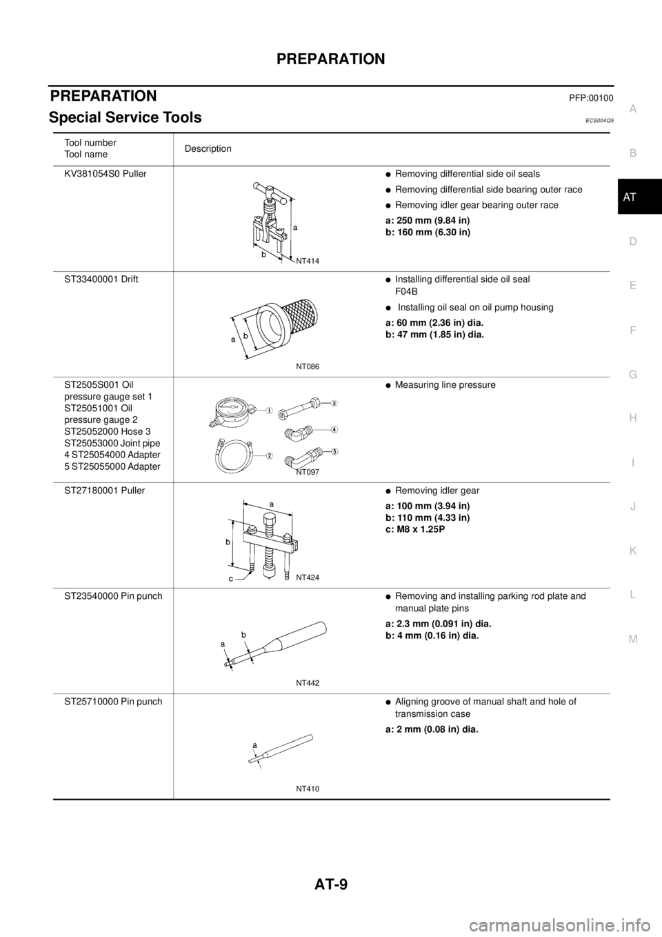
Special Service ToolsECS004Q5
Tool number
To o l n a m eDescription
KV381054S0 Puller
lRemoving differential side oil seals
lRemoving differential side bearing outer race
lRemoving idler gear bearing outer race
a: 250 mm (9.84 in)
b: 160 mm (6.30 in)
ST33400001 Drift
lInstalling differential side oil seal
F04B
lInstalling oil seal on oil pump housing
a: 60 mm (2.36 in) dia.
b: 47 mm (1.85 in) dia.
ST2505S001 Oil
pressure gauge set 1
ST25051001 Oil
pressure gauge 2
ST25052000 Hose 3
ST25053000 Joint pipe
4 ST25054000 Adapter
5 ST25055000 Adapter
lMeasuring line pressure
ST27180001 Puller
lRemoving idler gear
a: 100 mm (3.94 in)
b: 110 mm (4.33 in)
c: M8 x 1.25P
ST23540000 Pin punch
lRemoving and installing parking rod plate and
manual plate pins
a: 2.3 mm (0.091 in) dia.
b: 4 mm (0.16 in) dia.
ST25710000 Pin punch
lAligning groove of manual shaft and hole of
transmission case
a: 2 mm (0.08 in) dia.
NT414
NT086
NT097
NT424
NT442
NT410
Page 18 of 3066
AT-12
PREPARATION
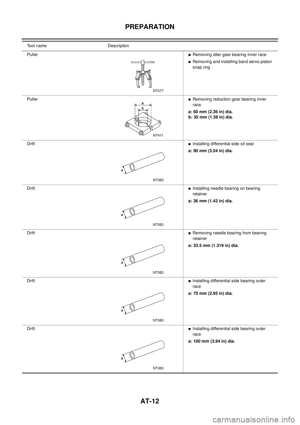
Tool name Description
Puller
lRemoving idler gear bearing inner race
lRemoving and installing band servo piston
snap ring
Puller
lRemoving reduction gear bearing inner
race
a: 60 mm (2.36 in) dia.
b: 35 mm (1.38 in) dia.
Drift
lInstalling differential side oil seal
a: 90 mm (3.54 in) dia.
Drift
lInstalling needle bearing on bearing
retainer
a: 36 mm (1.42 in) dia.
Drift
lRemoving needle bearing from bearing
retainer
a: 33.5 mm (1.319 in) dia.
Drift
lInstalling differential side bearing outer
race
a: 75 mm (2.95 in) dia.
Drift
lInstalling differential side bearing outer
race
a: 100 mm (3.94 in) dia.
NT077
NT411
NT083
NT083
NT083
NT083
NT083
Page 23 of 3066
OVERALL SYSTEM
AT-17
D
E
F
G
H
I
J
K
L
MA
B
AT
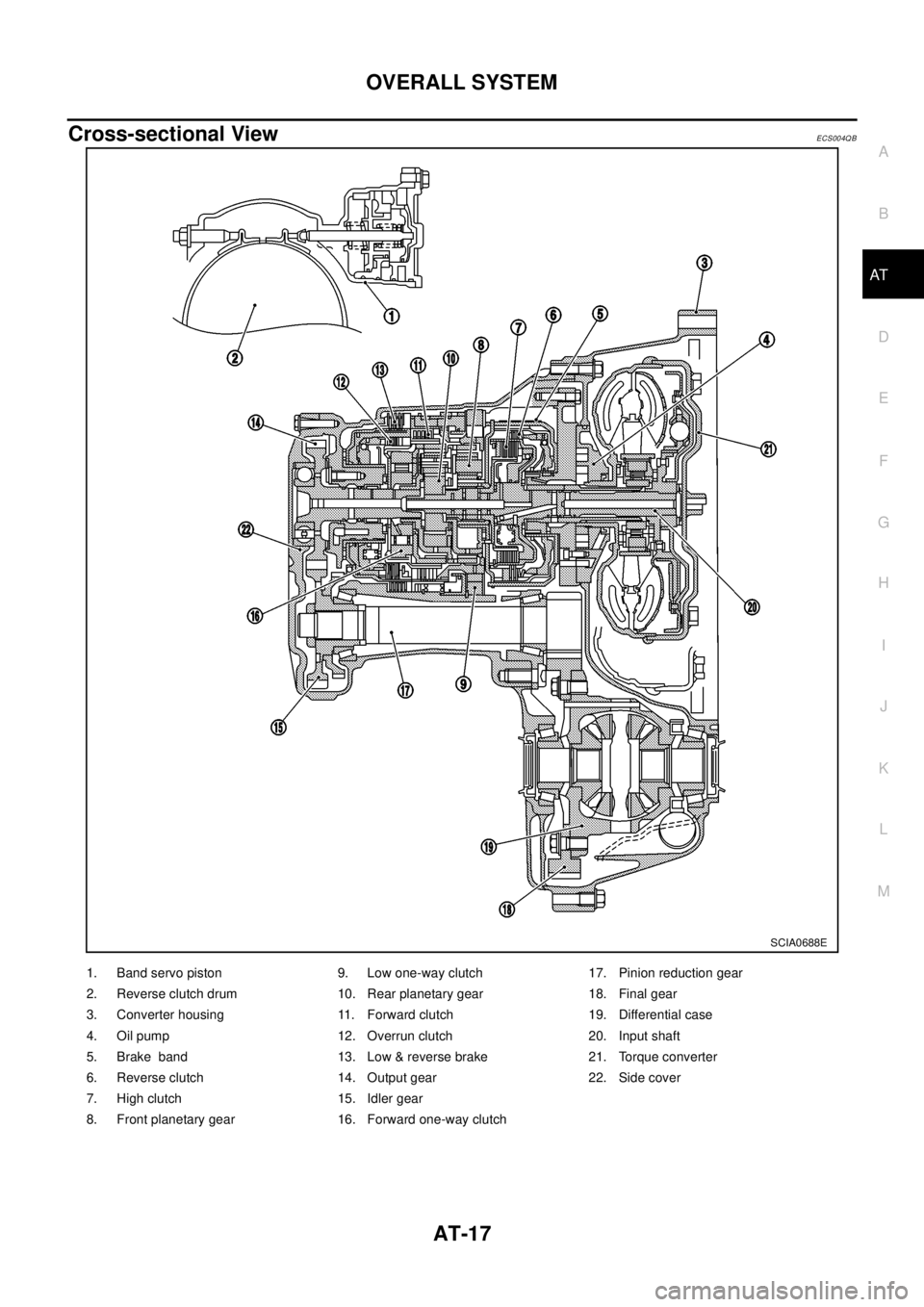
Cross-sectional ViewECS004QB
SCIA0688E
1. Band servo piston 9. Low one-way clutch 17. Pinion reduction gear
2. Reverse clutch drum 10. Rear planetary gear 18. Final gear
3. Converter housing 11. Forward clutch 19. Differential case
4. Oil pump 12. Overrun clutch 20. Input shaft
5. Brake band 13. Low & reverse brake 21. Torque converter
6. Reverse clutch 14. Output gear 22. Side cover
7. High clutch 15. Idler gear
8. Front planetary gear 16. Forward one-way clutch
Page 25 of 3066
OVERALL SYSTEM
AT-19
D
E
F
G
H
I
J
K
L
MA
B
AT
Shift MechanismECS004QD
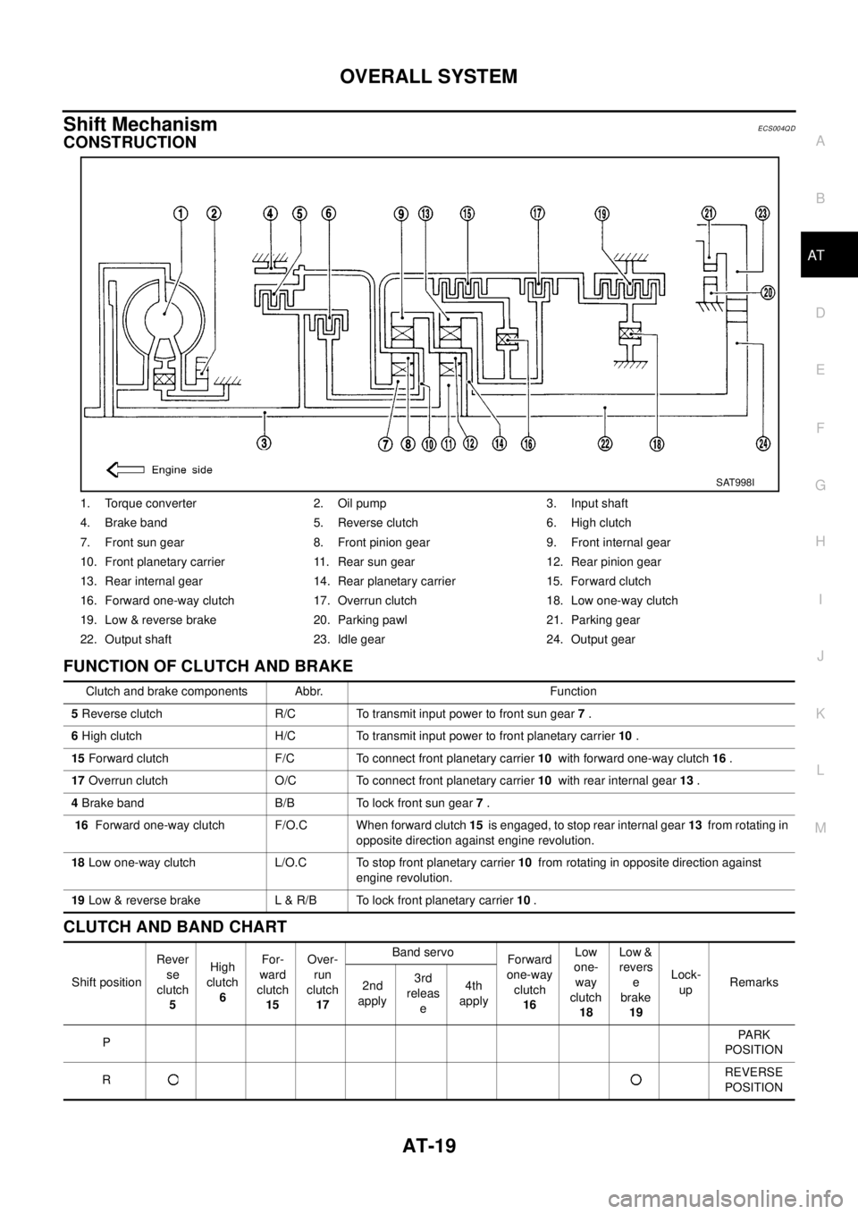
CONSTRUCTION
FUNCTION OF CLUTCH AND BRAKE
CLUTCH AND BAND CHART
1. Torque converter 2. Oil pump 3. Input shaft
4. Brake band 5. Reverse clutch 6. High clutch
7. Front sun gear 8. Front pinion gear 9. Front internal gear
10. Front planetary carrier 11. Rear sun gear 12. Rear pinion gear
13. Rear internal gear 14. Rear planetary carrier 15. Forward clutch
16. Forward one-way clutch 17. Overrun clutch 18. Low one-way clutch
19. Low & reverse brake 20. Parking pawl 21. Parking gear
22. Output shaft 23. Idle gear 24. Output gear
SAT998I
Clutch and brake components Abbr. Function
5Reverse clutch R/C To transmit input power to front sun gear7.
6High clutch H/C To transmit input power to front planetary carrier10.
15Forward clutch F/C To connect front planetary carrier10with forward one-way clutch16.
17Overrun clutch O/C To connect front planetary carrier10with rear internal gear13.
4Brake band B/B To lock front sun gear7.
16Forward one-way clutch F/O.C When forward clutch15is engaged, to stop rear internal gear13from rotating in
opposite direction against engine revolution.
18Low one-way clutch L/O.C To stop front planetary carrier10from rotating in opposite direction against
engine revolution.
19Low & reverse brake L & R/B To lock front planetary carrier10.
Shift positionRever
se
clutch
5High
clutch
6For-
ward
clutch
15Over-
run
clutch
17Band servo
Forward
one-way
clutch
16Low
one-
way
clutch
18Low &
revers
e
brake
19Lock-
upRemarks
2nd
apply3rd
releas
e4th
apply
PPA R K
POSITION
RREVERSE
POSITION
Page 26 of 3066
AT-20
OVERALL SYSTEM
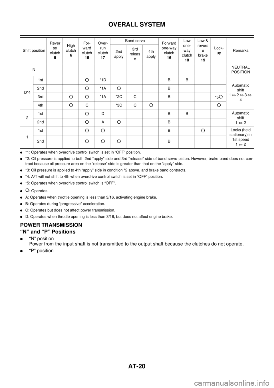
l*1: Operates when overdrive control switch is set in “OFF” position.
l*2: Oil pressure is applied to both 2nd “apply” side and 3rd “release” side of band servo piston. However, brake band does not con-
tract because oil pressure area on the “release” side is greater than that on the “apply” side.
l*3: Oil pressure is applied to 4th “apply” side in condition *2 above, and brake band contracts.
l*4: A/T will not shift to 4th when overdrive control switch is set in “OFF” position.
l*5: Operates when overdrive control switch is “OFF”.
l:Operates.
lA: Operates when throttle opening is less than 3/16, activating engine brake.
lB: Operates during “progressive” acceleration.
lC: Operates but does not affect power transmission.
lD: Operates when throttle opening is less than 3/16, but does not affect engine brake.
POWER TRANSMISSION
“N” and “P” Positions
l“N” position
Power from the input shaft is not transmitted to the output shaft because the clutches do not operate.
l“P” position
NNEUTRAL
POSITION
D*41st *1D B B
Automatic
shift
1Û2Û3Û
4 2nd *1A B
3rd *1A *2C C B
*5
4th C *3C C
21st D B BAutomatic
shift
1Û2 2nd A B
11stBLocks (held
stationary) in
1st speed
1Ü2 2ndB Shift positionRever
se
clutch
5High
clutch
6For-
ward
clutch
15Over-
run
clutch
17Band servo
Forward
one-way
clutch
16Low
one-
way
clutch
18Low &
revers
e
brake
19Lock-
upRemarks
2nd
apply3rd
releas
e4th
apply
Page 37 of 3066
OVERALL SYSTEM
AT-31
D
E
F
G
H
I
J
K
L
MA
B
AT
Control of Shift Valves A and B
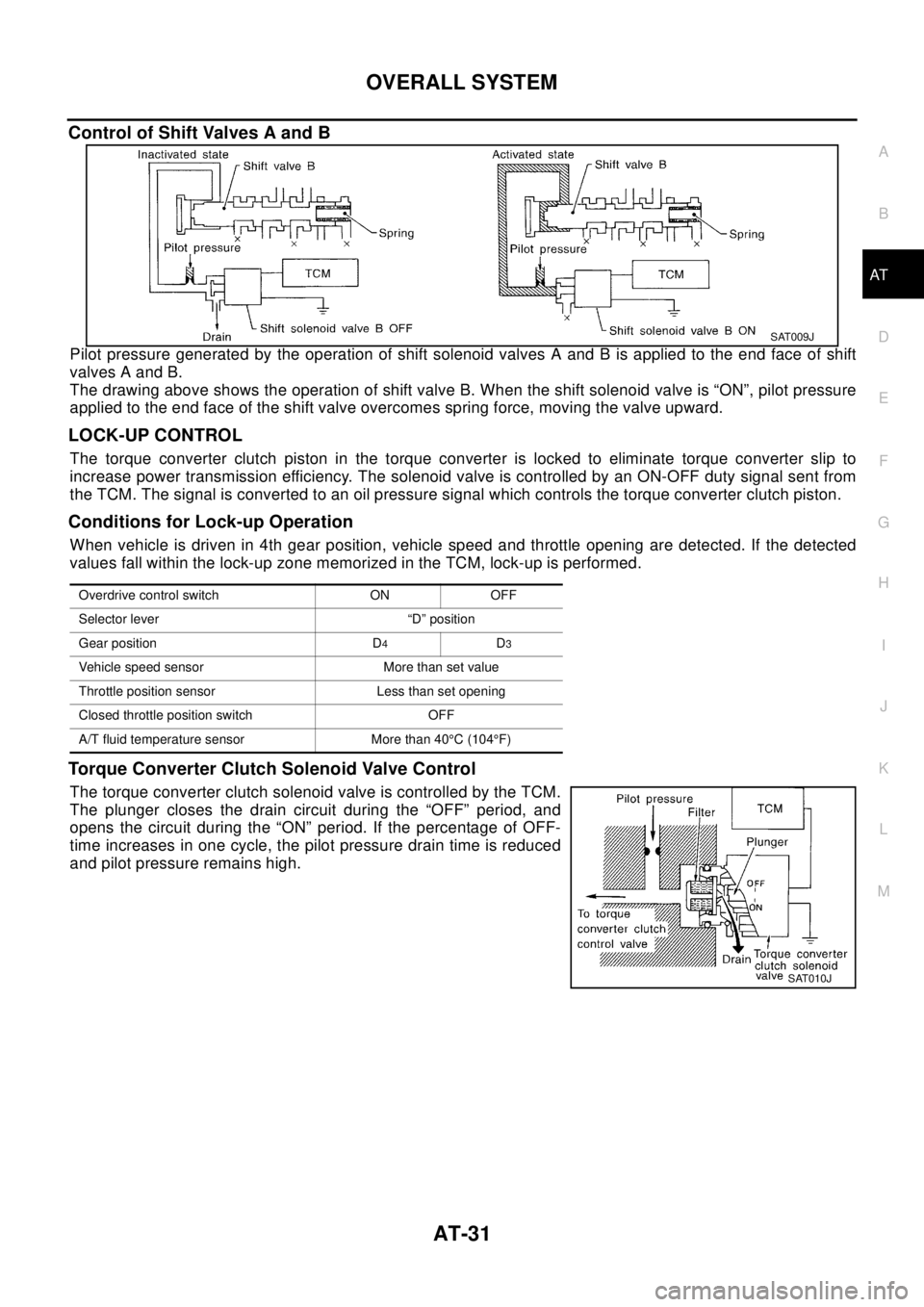
Pilot pressure generated by the operation of shift solenoid valves A and B is applied to the end face of shift
valves A and B.
The drawing above shows the operation of shift valve B. When the shift solenoid valve is “ON”, pilot pressure
applied to the end face of the shift valve overcomes spring force, moving the valve upward.
LOCK-UP CONTROL
The torque converter clutch piston in the torque converter is locked to eliminate torque converter slip to
increase power transmission efficiency. The solenoid valve is controlled by an ON-OFF duty signal sent from
the TCM. The signal is converted to an oil pressure signal which controls the torque converter clutch piston.
Conditions for Lock-up Operation
When vehicle is driven in 4th gear position, vehicle speed and throttle opening are detected. If the detected
values fall within the lock-up zone memorized in the TCM, lock-up is performed.
Torque Converter Clutch Solenoid Valve Control
The torque converter clutch solenoid valve is controlled by the TCM.
The plunger closes the drain circuit during the “OFF” period, and
opens the circuit during the “ON” period. If the percentage of OFF-
time increases in one cycle, the pilot pressure drain time is reduced
and pilot pressure remains high.
SAT009J
Overdrive control switch ON OFF
Selector lever “D” position
Gear position D
4D3
Vehicle speed sensor More than set value
Throttle position sensor Less than set opening
Closed throttle position switch OFF
A/T fluid temperature sensor More than 40°C(104°F)
SAT010J
Page 39 of 3066
OVERALL SYSTEM
AT-33
D
E
F
G
H
I
J
K
L
MA
B
AT
Overrun Clutch Solenoid Valve Control
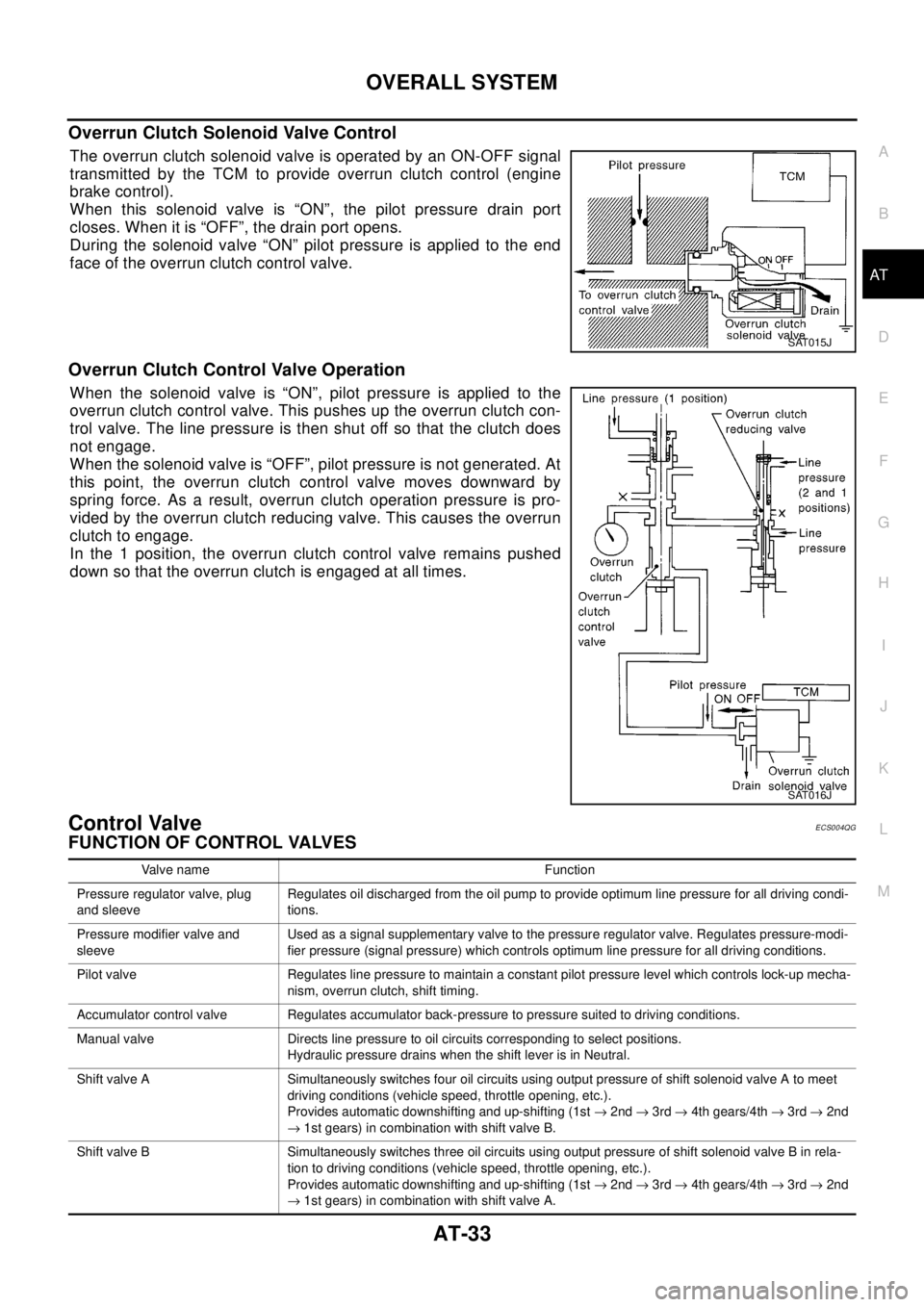
TheoverrunclutchsolenoidvalveisoperatedbyanON-OFFsignal
transmitted by the TCM to provide overrun clutch control (engine
brake control).
When this solenoid valve is “ON”, the pilot pressure drain port
closes. When it is “OFF”, the drain port opens.
During the solenoid valve “ON” pilot pressure is applied to the end
face of the overrun clutch control valve.
Overrun Clutch Control Valve Operation
When the solenoid valve is “ON”, pilot pressure is applied to the
overrun clutch control valve. This pushes up the overrun clutch con-
trol valve. The line pressure is then shut off so that the clutch does
not engage.
When the solenoid valve is “OFF”, pilot pressure is not generated. At
this point, the overrun clutch control valve moves downward by
spring force. As a result, overrun clutch operation pressure is pro-
vided by the overrun clutch reducing valve. This causes the overrun
clutch to engage.
In the 1 position, the overrun clutch control valve remains pushed
down so that the overrun clutch is engaged at all times.
Control ValveECS004QG
FUNCTION OF CONTROL VALVES
SAT015J
SAT016J
Valve name Function
Pressure regulator valve, plug
and sleeveRegulates oil discharged from the oil pump to provide optimum line pressure for all driving condi-
tions.
Pressure modifier valve and
sleeveUsed as a signal supplementary valve to the pressure regulator valve. Regulates pressure-modi-
fier pressure (signal pressure) which controls optimum line pressure for all driving conditions.
Pilot valve Regulates line pressure to maintain a constant pilot pressure level which controls lock-up mecha-
nism, overrun clutch, shift timing.
Accumulator control valve Regulates accumulator back-pressure to pressure suited to driving conditions.
Manual valve Directs line pressure to oil circuits corresponding to select positions.
Hydraulic pressure drains when the shift lever is in Neutral.
Shift valve A Simultaneously switches four oil circuits using output pressure of shift solenoid valve A to meet
driving conditions (vehicle speed, throttle opening, etc.).
Provides automatic downshifting and up-shifting (1st®2nd®3rd®4th gears/4th®3rd®2nd
®1st gears) in combination with shift valve B.
Shift valve B Simultaneously switches three oil circuits using output pressure of shift solenoid valve B in rela-
tion to driving conditions (vehicle speed, throttle opening, etc.).
Provides automatic downshifting and up-shifting (1st®2nd®3rd®4th gears/4th®3rd®2nd
®1st gears) in combination with shift valve A.