2003 NISSAN X-TRAIL turn signal bulb
[x] Cancel search: turn signal bulbPage 886 of 3066
![NISSAN X-TRAIL 2003 Electronic Repair Manual BRC-18
[4WD/ABS]
TROUBLE DIAGNOSIS
Trouble Diagnosis Chart by Symptom
EFS001BF
When ABS and 4WD warning lamps illuminate, perform self-diagnosis.
Symptom Condition Check items Reference page
When igni NISSAN X-TRAIL 2003 Electronic Repair Manual BRC-18
[4WD/ABS]
TROUBLE DIAGNOSIS
Trouble Diagnosis Chart by Symptom
EFS001BF
When ABS and 4WD warning lamps illuminate, perform self-diagnosis.
Symptom Condition Check items Reference page
When igni](/manual-img/5/57402/w960_57402-885.png)
BRC-18
[4WD/ABS]
TROUBLE DIAGNOSIS
Trouble Diagnosis Chart by Symptom
EFS001BF
When ABS and 4WD warning lamps illuminate, perform self-diagnosis.
Symptom Condition Check items Reference page
When ignition switch is turned ON,
drive mode indicator lamp does not illu-
minate for Approx. 1 second (drive
mode lamp check)IGN-ON
lBlown drive mode indicator lamp bulb
lBlown fuse between ignition and drive mode
indicator lamp
lOpen circuit of wiring between ignition and
drive mode indicator lampBRC-42
ABS warning lamp does not illuminate
with ignition ON. (ABS warning lamp
check)IGN-ON
lBlown ABS warning lamp bulb
lBlown fuse between ignition and ABS warning
lamp.
lOpen circuit of wiring between ignition and
ABS warning lamp.
lMalfunction in ABS systemBRC-42
ABS warning lamp illuminates with
ignition ON, but does not illuminates
after a few seconds. (ABS warning
lamp has not illuminated.)IGN-ONl4WD/ABS control unit connector discon-
nected
lMalfunction in ABS systemBRC-42
4WD warning lamp does not illuminate
with ignition ON.IGN-ON
lBlown 4WD warning lamp bulb
lBlown fuse between ignition and 4WD warn-
ing lamp
lOpen circuit in wire between ignition and 4WD
warning lamp
lOpen circuit in wire between 4WD warning
lamp and 4WD actuator relay
lDisconnected 4WD actuator relay
lOpen circuit in wire between 4WD actuator
relay and body groundBRC-43
4WD warning lamp does not go out
several seconds after engine is started.
(Drive mode indicator lamp goes out.)Engine runningl4WD/ABS control unit connector discon-
nected
lMalfunction present in 4WD systemBRC-43
Heavy tight-corner braking symptom
occurs when vehicle is driven in the fol-
lowing conditions: AUTO mode and
steering wheel is turned fully to either
sides after engine is started (Note 1,
Note 2).lEngine run-
ning
lAUTO mode
lSteering
wheel fully
turned
lOperation is not in AUTO mode (in 2WD or
LOCK mode).
lThrottle position signal error
lMechanical malfunction of electronically con-
trolled coupling
lMalfunction present in 4WD systemBRC-44
Drive modes cannot be switched after
engine is started.Engine running
lDrive mode change-over switch is discon-
nected.
lOpen circuit between drive mode change-over
switch and 4WD /ABS control unit
lOpen circuit between drive mode change-over
switch and body groundBRC-45
Vehicle running, 4WD warning lamp
flashes rapidly. (When it flashes for
Approx. One minute, then does not illu-
minate.) Rapid flashing: Two times
flashing per 1 secondEngine running
(to other than
2WD mode)Protection function was activated due to heavy
load to electronically controlled coupling. (4WD
system is not malfunctioning.)BRC-45
Page 906 of 3066
![NISSAN X-TRAIL 2003 Electronic Repair Manual BRC-38
[4WD/ABS]
TROUBLE DIAGNOSIS
4.HARNESS CONTINUITY INSPECTION
Drive the vehicle for a while and the perform self-diagnosis.
OK or NG
OK >> End
NG >>
l4WD/ABS control unit input/output signal insp NISSAN X-TRAIL 2003 Electronic Repair Manual BRC-38
[4WD/ABS]
TROUBLE DIAGNOSIS
4.HARNESS CONTINUITY INSPECTION
Drive the vehicle for a while and the perform self-diagnosis.
OK or NG
OK >> End
NG >>
l4WD/ABS control unit input/output signal insp](/manual-img/5/57402/w960_57402-905.png)
BRC-38
[4WD/ABS]
TROUBLE DIAGNOSIS
4.HARNESS CONTINUITY INSPECTION
Drive the vehicle for a while and the perform self-diagnosis.
OK or NG
OK >> End
NG >>
l4WD/ABS control unit input/output signal inspection
lRecheck 4WD control unit connector terminals and connection.
Trouble Diagnoses for SymptomsEFS001CC
4WD INDICATOR LAMP DOES NOT COME ON FOR APPROXIMATELY 1 SECOND WHEN THE
IGNITION SWITCH IS TURNED TO ON
Inspection Procedure
1.CHECK BLOWN FUSES BETWEEN IGN AND COMBINATION METER
Check that there are no blown fuses between IGN and combination meter.
OK or NG
OK >> GO TO 2.
NG >> Replace fuse and check again.
2.CHECK CONTINUITY BETWEEN COMBINATION METER AND 4WD/ABS CONTROL UNIT
1. Disconnect combination meter connector and 4WD/ABS control unit connector.
2. Check continuity between combination meter harness connector M44 terminal No.18 (Y/G) and 4WD/ABS
control unit harness C/U connector E122 terminal No.16 (Y/G).
OK or NG
OK >> GO TO 3.
NG >> Check harness between combination meter and 4WD/ABS control unit.
3.CHECK COMBINATION METER POWER CIRCUIT
1. Disconnect combination meter connector.
2. With ignition ON, check the voltage between the combination meter harness connector M44 terminal
No.46 (W/L) (LHD models) or No.59 (W/L) (RHD models) and body ground.
OK or NG
OK >> GO TO 4.
NG >> Check combination meter circuits.
4.CHECK 4WD AUTO LAMP (ON COMBINATION METER) CIRCUIT
Check continuity between combination meter terminal 46 (LHD models) or 59 (RHD models) and terminal 18.
OK or NG
OK >> Using CONSULT-II perform self-diagnosis.
NG >> Check for burned-out bulb in 4WD AUTO lamp.18 (YG) - 16 (Y/G) : Continuity should exist.
LHD models:46 (W/L), RHD models: 59 (W/L) 1(W) - Body ground:
Battery voltage
46 (LHD models) or 59 (RHD models) - 18:
Continuity should exist.
Page 2399 of 3066

LT-1
LIGHTING SYSTEM
K ELECTRICAL
CONTENTS
C
D
E
F
G
H
I
J
L
M
SECTION
A
B
LT
LIGHTING SYSTEM
PRECAUTION ............................................................ 3
Precautions for Supplemental Restraint System
(SRS) “AIR BAG” and “SEAT BELT PRE-TEN-
SIONER” .................................................................. 3
Precaution ................................................................ 3
Wiring Diagrams and Trouble Diagnosis .................. 3
HEADLAMP ................................................................ 4
System Description .................................................. 4
DESCRIPTION ...................................................... 4
LOW BEAM OPERATION ..................................... 4
HIGH BEAM OPERATION/FLASH-TO-PASS
OPERATION ......................................................... 4
Wiring Diagram — H/LAMP — ................................. 5
Trouble Diagnoses ................................................... 6
Aiming Adjustment ................................................... 6
LOW BEAM ........................................................... 7
Bulb Replacement .................................................... 8
HEAD LAMP ......................................................... 8
CLEARANCE LAMP ............................................. 8
Removal and Installation .......................................... 8
REMOVAL ............................................................. 8
INSTALLATION ..................................................... 8
HEADLAMP - DAYTIME LIGHT SYSTEM - ............... 9
System Description .................................................. 9
DESCRIPTION ...................................................... 9
HEADLAMP OPERATION (DAYTIME LIGHT
CANCEL OPERATION) ........................................ 9
DAYTIME LIGHT OPERATION ............................. 9
Schematic .............................................................. 10
Wiring Diagram -DTRL- ...........................................11
Trouble Diagnoses ................................................. 14
DAYTIME LIGHT UNIT INSPECTION TABLE .... 14
Bulb Replacement .................................................. 14
Aiming Adjustment ................................................. 14
HEADLAMP AIMING CONTROL ............................. 15
Wiring Diagram -H/AIM- ......................................... 15
Removal and Installation ........................................ 16
Switch Circuit Inspection ........................................ 16
TURN SIGNAL AND HAZARD WARNING LAMPS... 17System Description ................................................. 17
TURN SIGNAL OPERATION .............................. 17
HAZARD LAMP OPERATION ............................. 17
Wiring Diagram — TURN — ................................... 19
Trouble Diagnoses ................................................. 21
Electrical Components Inspection .......................... 21
COMBINATION FLASHER UNIT CHECK ........... 21
Bulb Replacement .................................................. 22
FRONT TURN SIGNAL LAMP ............................ 22
SIDE TURN SIGNAL LAMP ................................ 22
REAR TURN SIGNAL LAMP .............................. 22
Removal and Installation for Front Turn Signal Lamp... 22
REMOVAL ........................................................... 22
INSTALLATION ................................................... 22
Removal and Installation for Side Turn Signal Lamp... 23
Removal and Installation for Rear Turn Signal Lamp... 23
LIGHTING AND TURN SIGNAL SWITCH ................ 24
Removal and Installation ........................................ 24
Switch Circuit Inspection ........................................ 24
HAZARD SWITCH .................................................... 25
Removal and Installation ........................................ 25
REMOVAL ........................................................... 25
INSTALLATION ................................................... 25
STOP LAMP .............................................................. 26
Wiring Diagram — STOP/L — ................................ 26
Bulb Replacement .................................................. 27
STOP LAMP ........................................................ 27
HIGH-MOUNTED STOP LAMP ........................... 27
Removal and Installation ........................................ 27
STOP LAMP ........................................................ 27
HIGH-MOUNTED STOP LAMP ........................... 27
BACK-UP LAMP ....................................................... 28
Wiring Diagram — BACK/L — ................................ 28
Bulb Replacement .................................................. 29
Removal and Installation ........................................ 29
PARKING, LICENSE PLATE AND TAIL LAMPS ..... 30
Wiring Diagram — TAIL/L — .................................. 30
Bulb Replacement .................................................. 32
PARKING AND TAIL LAMPS .............................. 32
Page 2406 of 3066

LT-8
HEADLAMP
Bulb Replacement
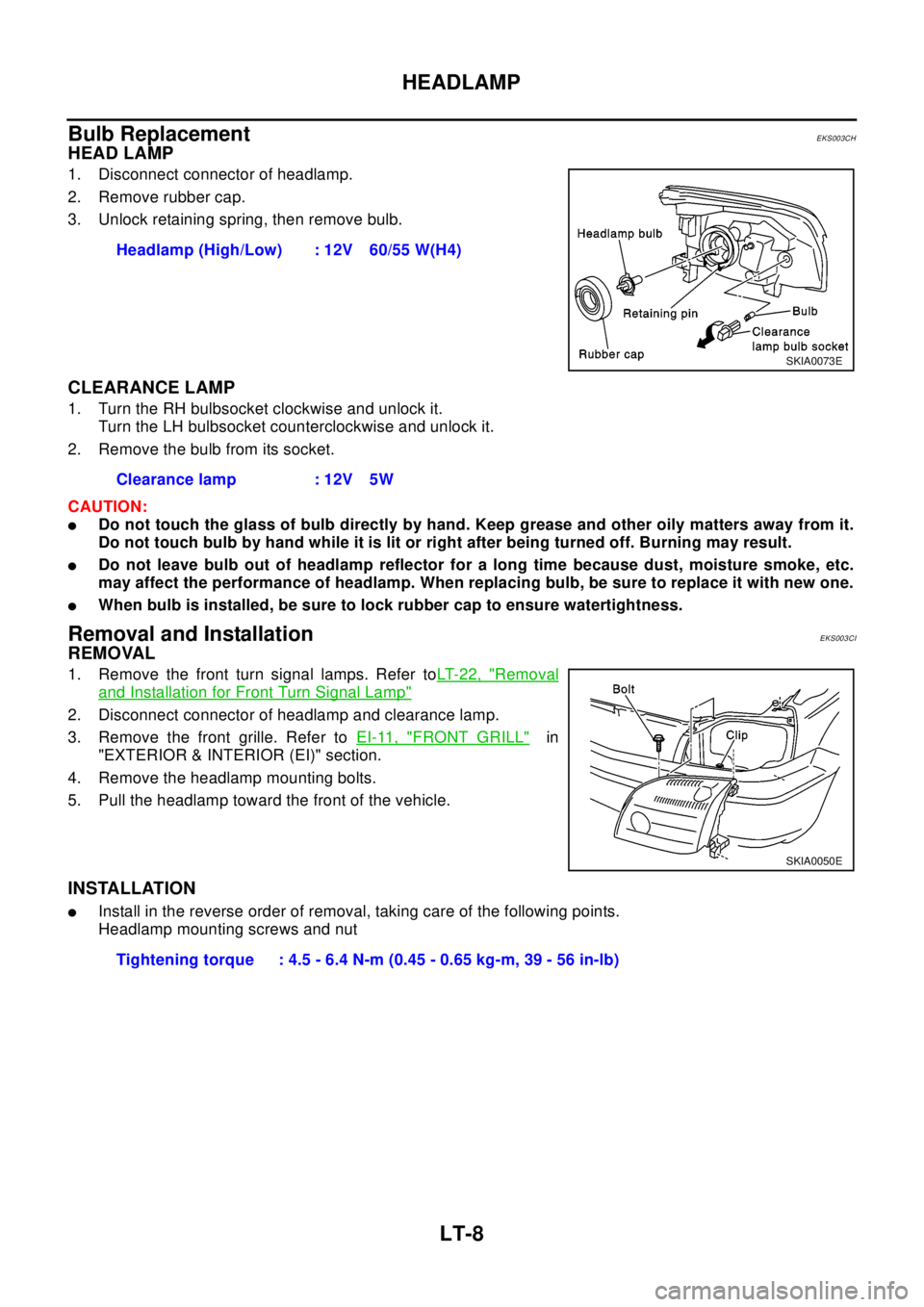
EKS003CH
HEAD LAMP
1. Disconnect connector of headlamp.
2. Remove rubber cap.
3. Unlock retaining spring, then remove bulb.
CLEARANCE LAMP
1. Turn the RH bulbsocket clockwise and unlock it.
Turn the LH bulbsocket counterclockwise and unlock it.
2. Remove the bulb from its socket.
CAUTION:
lDo not touch the glass of bulb directly by hand. Keep grease and other oily matters away from it.
Do not touch bulb by hand while it is lit or right after being turned off. Burning may result.
lDo not leave bulb out of headlamp reflector for a long time because dust, moisture smoke, etc.
may affect the performance of headlamp. When replacing bulb, be sure to replace it with new one.
lWhen bulb is installed, be sure to lock rubber cap to ensure watertightness.
Removal and InstallationEKS003CI
REMOVAL
1. Remove the front turn signal lamps. Refer toLT-22, "Removal
and Installation for Front Turn Signal Lamp"
2. Disconnect connector of headlamp and clearance lamp.
3. Remove the front grille. Refer toEI-11, "
FRONT GRILL"in
"EXTERIOR & INTERIOR (EI)" section.
4. Remove the headlamp mounting bolts.
5. Pull the headlamp toward the front of the vehicle.
INSTALLATION
lInstall in the reverse order of removal, taking care of the following points.
Headlamp mounting screws and nutHeadlamp (High/Low) : 12V 60/55 W(H4)
SKIA0073E
Clearance lamp : 12V 5W
SKIA0050E
Tightening torque : 4.5 - 6.4 N-m (0.45 - 0.65 kg-m, 39 - 56 in-lb)
Page 2419 of 3066

TURN SIGNAL AND HAZARD WARNING LAMPS
LT-21
C
D
E
F
G
H
I
J
L
MA
B
LT
Trouble DiagnosesEKS003BG
Electrical Components InspectionEKS0034C
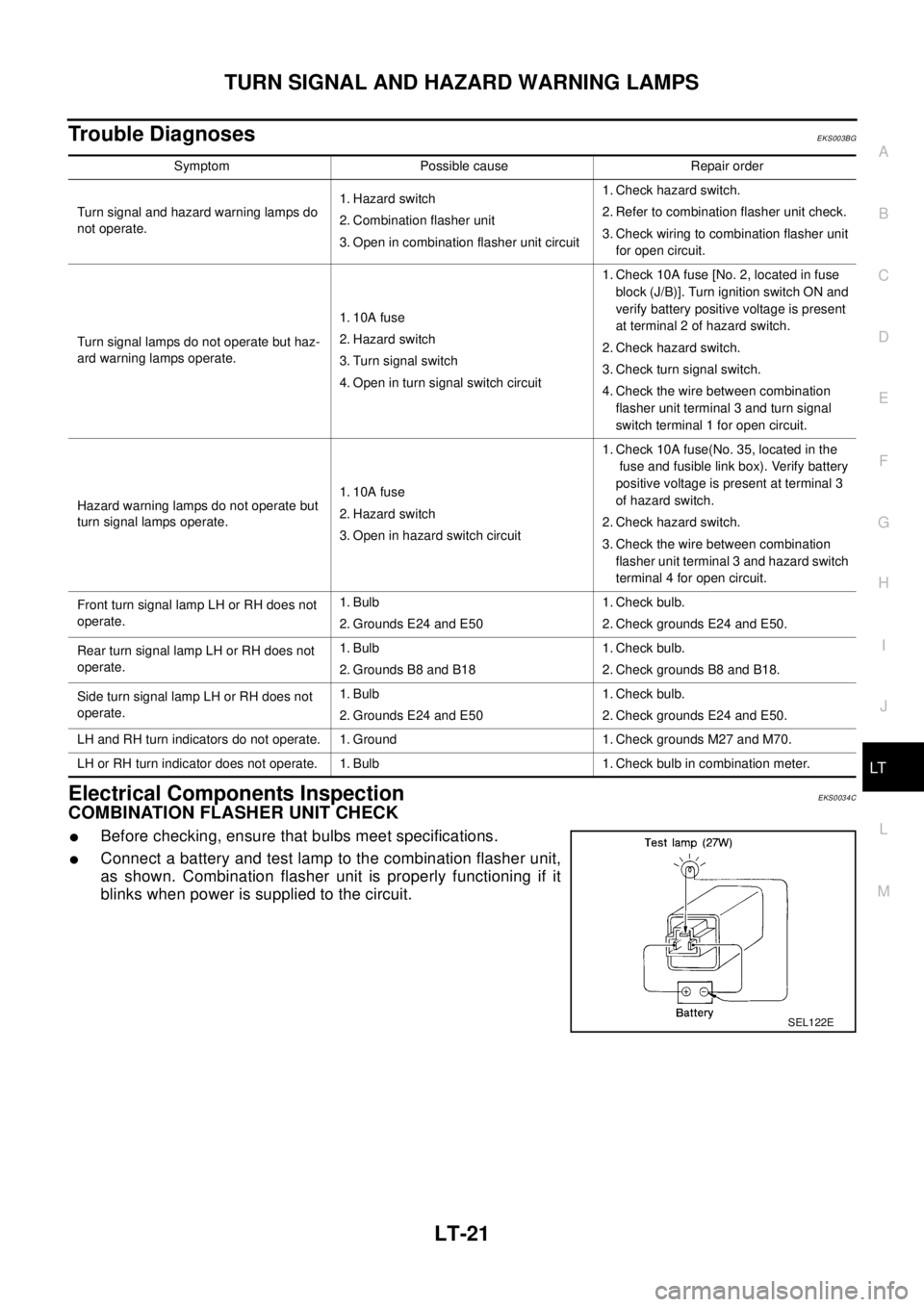
COMBINATION FLASHER UNIT CHECK
lBefore checking, ensure that bulbs meet specifications.
lConnect a battery and test lamp to the combination flasher unit,
as shown. Combination flasher unit is properly functioning if it
blinks when power is supplied to the circuit.
Symptom Possible cause Repair order
Turn signal and hazard warning lamps do
not operate.1. Hazard switch
2. Combination flasher unit
3. Open in combination flasher unit circuit1. Check hazard switch.
2. Refer to combination flasher unit check.
3. Check wiring to combination flasher unit
for open circuit.
Turn signal lamps do not operate but haz-
ard warning lamps operate.1. 10A fuse
2. Hazard switch
3. Turn signal switch
4. Open in turn signal switch circuit1. Check 10A fuse [No. 2, located in fuse
block (J/B)]. Turn ignition switch ON and
verify battery positive voltage is present
at terminal 2 of hazard switch.
2. Check hazard switch.
3. Check turn signal switch.
4. Check the wire between combination
flasher unit terminal 3 and turn signal
switch terminal 1 for open circuit.
Hazard warning lamps do not operate but
turn signal lamps operate.1. 10A fuse
2. Hazard switch
3. Open in hazard switch circuit1. Check 10A fuse(No. 35, located in the
fuse and fusible link box). Verify battery
positive voltage is present at terminal 3
of hazard switch.
2. Check hazard switch.
3. Check the wire between combination
flasher unit terminal 3 and hazard switch
terminal 4 for open circuit.
Front turn signal lamp LH or RH does not
operate.1. Bulb
2. Grounds E24 and E501. Check bulb.
2. Check grounds E24 and E50.
Rear turn signal lamp LH or RH does not
operate.1. Bulb
2. Grounds B8 and B181. Check bulb.
2. Check grounds B8 and B18.
Side turn signal lamp LH or RH does not
operate.1. Bulb
2. Grounds E24 and E501. Check bulb.
2. Check grounds E24 and E50.
LH and RH turn indicators do not operate. 1. Ground 1. Check grounds M27 and M70.
LH or RH turn indicator does not operate. 1. Bulb 1. Check bulb in combination meter.
SEL122E
Page 2420 of 3066

LT-22
TURN SIGNAL AND HAZARD WARNING LAMPS
Bulb Replacement
EKS0034D
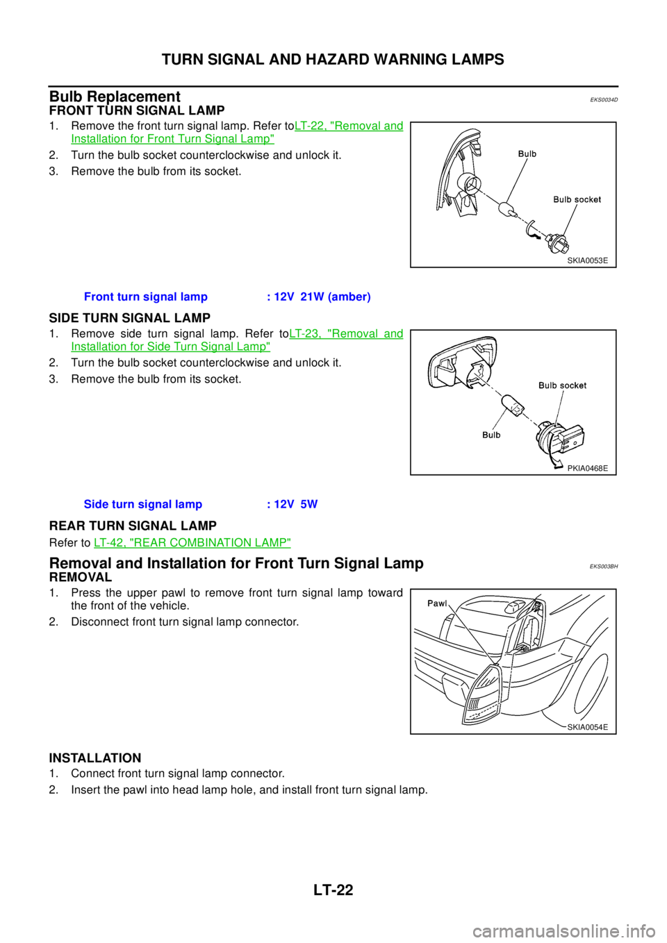
FRONT TURN SIGNAL LAMP
1. Remove the front turn signal lamp. Refer toLT- 2 2 , "Removal and
Installation for Front Turn Signal Lamp"
2. Turn the bulb socket counterclockwise and unlock it.
3. Remove the bulb from its socket.
SIDE TURN SIGNAL LAMP
1. Remove side turn signal lamp. Refer toLT- 2 3 , "Removal and
Installation for Side Turn Signal Lamp"
2. Turn the bulb socket counterclockwise and unlock it.
3. Remove the bulb from its socket.
REAR TURN SIGNAL LAMP
Refer toLT- 4 2 , "REAR COMBINATION LAMP"
Removal and Installation for Front Turn Signal LampEKS003BH
REMOVAL
1. Press the upper pawl to remove front turn signal lamp toward
the front of the vehicle.
2. Disconnect front turn signal lamp connector.
INSTALLATION
1. Connect front turn signal lamp connector.
2. Insert the pawl into head lamp hole, and install front turn signal lamp.
SKIA0053E
Front turn signal lamp : 12V 21W (amber)
PKIA0468E
Side turn signal lamp : 12V 5W
SKIA0054E
Page 2441 of 3066

REAR COMBINATION LAMP
LT-43
C
D
E
F
G
H
I
J
L
MA
B
LT
Bulb ReplacementEKS00164
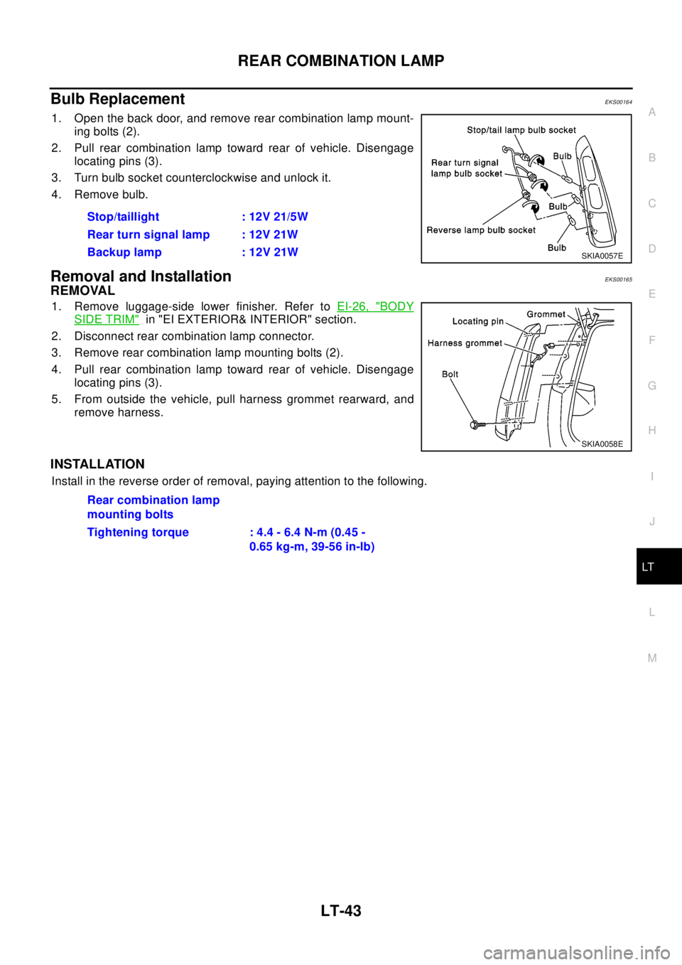
1. Open the back door, and remove rear combination lamp mount-
ing bolts (2).
2. Pull rear combination lamp toward rear of vehicle. Disengage
locating pins (3).
3. Turn bulb socket counterclockwise and unlock it.
4. Remove bulb.
Removal and InstallationEKS00165
REMOVAL
1. Remove luggage-side lower finisher. Refer toEI-26, "BODY
SIDE TRIM"in "EI EXTERIOR& INTERIOR" section.
2. Disconnect rear combination lamp connector.
3. Remove rear combination lamp mounting bolts (2).
4. Pull rear combination lamp toward rear of vehicle. Disengage
locating pins (3).
5. From outside the vehicle, pull harness grommet rearward, and
remove harness.
INSTALLATION
Install in the reverse order of removal, paying attention to the following.Stop/taillight : 12V 21/5W
Rear turn signal lamp : 12V 21W
Backup lamp : 12V 21W
SKIA0057E
SKIA0058E
Rear combination lamp
mounting bolts
Tightening torque : 4.4 - 6.4 N-m (0.45 -
0.65 kg-m, 39-56 in-lb)
Page 2465 of 3066

BULB SPECIFICATIONS
LT-67
C
D
E
F
G
H
I
J
L
MA
B
LT
BULB SPECIFICATIONSPFP:26297
HeadlampEKS003GS
Exterior LampEKS003GT
Interior Lamp/IlluminationEKS003GU
Item Wattage (W)
Low/High55 /60(H4)
Item Wattage (W)
Front combination lamp Clearance lamp 5
Front turn signal lamp21(amber)
Side turn signal lamp5
Fog lampFront fog lamp 55(H3)
Rear fog lamp 21
Rear combination lampStop/Tail lamp 21/5
Turn signal lamp 21
Back-up lamp 21
License plate lamp5
High-mounted stop lamp5
Item Wattage (W)
Interior room lamp10
Spot lampWithout sunroof 8
With sunroof 10
Luggage room lamp10