2003 NISSAN X-TRAIL transmission
[x] Cancel search: transmissionPage 2290 of 3066

LIFTING POINT
GI-37
LIFTING POINTPFP:00000
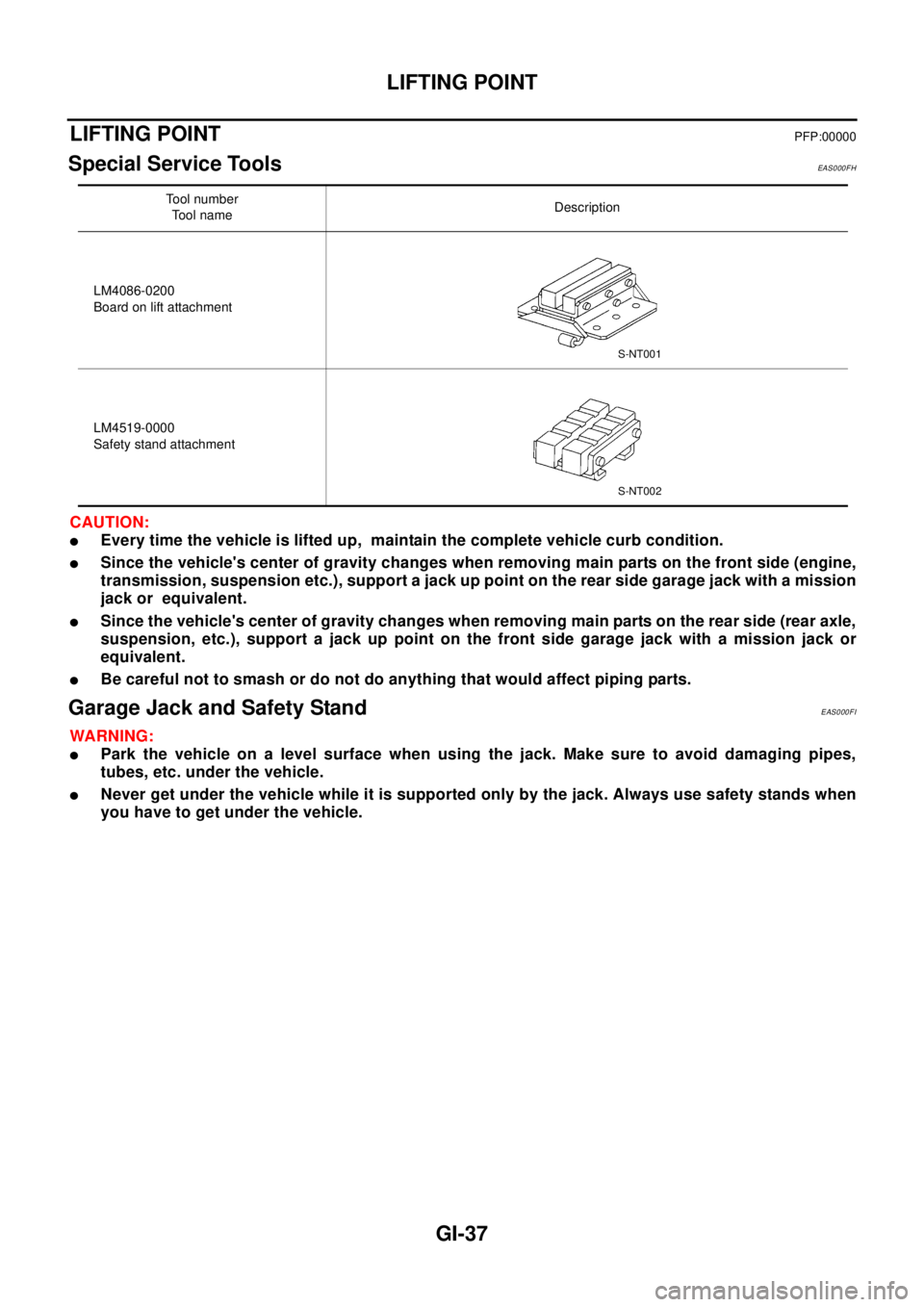
Special Service ToolsEAS000FH
CAUTION:
lEvery time the vehicle is lifted up, maintain the complete vehicle curb condition.
lSince the vehicle's center of gravity changes when removing main parts on the front side (engine,
transmission, suspension etc.), support a jack up point on the rear side garage jack with a mission
jack or equivalent.
lSince the vehicle's center of gravity changes when removing main parts on the rear side (rear axle,
suspension, etc.), support a jack up point on the front side garage jack with a mission jack or
equivalent.
lBe careful not to smash or do not do anything that would affect piping parts.
Garage Jack and Safety StandEAS000FI
WA RN ING:
lPark the vehicle on a level surface when using the jack. Make sure to avoid damaging pipes,
tubes, etc. under the vehicle.
lNever get under the vehicle while it is supported only by the jack. Always use safety stands when
you have to get under the vehicle.
Tool number
To o l n a m eDescription
LM4086-0200
Board on lift attachment
LM4519-0000
Safety stand attachment
S-NT001
S-NT002
Page 2293 of 3066

GI-40
TOW TRUCK TOWING
TOW TRUCK TOWING
PFP:00000
To w Tr u c k To w i n gEAS000FL
CAUTION:
lAll applicable local laws regarding the towing operation must be obeyed.
lIt is necessary to use proper towing equipment to avoid possible damage to the vehicle during
towing operation. Towing is in accordance with Towing Procedure Manual at dealer.
lAlways attach safety chains before towing.
lWhen towing, make sure that the transmission, steering system and power train are in good order.
If any unit is damaged, dollies must be used.
lNever tow an automatic transmission model from the rear (that is backward) with four wheels on
the ground. This may cause serious and expensive damage to the transmission.
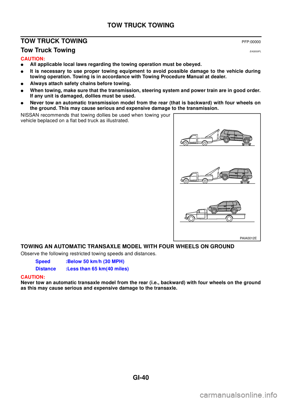
NISSAN recommends that towing dollies be used when towing your
vehicle beplaced on a flat bed truck as illustrated.
TOWING AN AUTOMATIC TRANSAXLE MODEL WITH FOUR WHEELS ON GROUND
Observe the following restricted towing speeds and distances.
CAUTION:
Never tow an automatic transaxle model from the rear (i.e., backward) with four wheels on the ground
as this may cause serious and expensive damage to the transaxle.
PAIA0012E
Speed :Below 50 km/h (30 MPH)
Distance :Less than 65 km(40 miles)
Page 2303 of 3066

GI-50
TERMINOLOGY
Torque converter clutch solenoid valve TCC solenoid valveLock-up cancel solenoid
Lock-up solenoid
Transmission control module TCM A/T control unit
Turbocharger TC Turbocharger
Vehicle speed sensor VSS Vehicle speed sensor
Volume air flow sensor VAFS Air flow meter
Warm up oxidation catalyst WU-OC Catalyst
Warm up oxidation catalytic converter sys-
temWU-OC system ***
Warm up three way catalyst WU-TWC Catalyst
Warm up three way catalytic converter sys-
temWU-TWC system ***
Wide open throttle position switch WOTP switch Full switchNEW TERMNEW ACRONYM /
ABBREVIATIONOLD TERM
Page 2359 of 3066

IDX-2
ALPHABETICAL INDEX
Numerics
4WD mode switch ...................................TF-53
,TF-57
4WD shift indicator lamp .........................TF-32,TF-54
4WD solenoid valve ................................TF-49,TF-51
4WD warning lamp ..........TF-32,TF-40,TF-55,TF-58
A
A/C air flow .........................................ATC-28
,MTC-5
A/C component layout .....................................ATC-20
A/C compressor clutch removal and installation ...........
ATC-129
A/C compressor precaution ...............................ATC-7
A/C compressor special service tool ................ATC-11
A/C diagnostic work flow (auto A/C) ................ATC-30
A/C HFC134a (R134a) system precaution ........ATC-4
A/C HFC134a (R134a) system service procedure .......
ATC-123
A/C HFC134a (R134a) system service tools ...ATC-12
A/C HFC134a system service equipment precaution ...
ATC-8
A/C lubricant (R134a) ......................................ATC-21
A/C operational check .........................ATC-51,MTC-7
A/C performance test diagnoses .....................ATC-83
A/C reray ..........................................................ATC-80
A/C self-diagnoses (auto A/C) .........................ATC-42
A/C service data specification ........................ATC-143
A/C system description (auto A/C) ...................ATC-24
A/C trouble diagnoses (auto A/C) .......ATC-30,MTC-3
A/C, A - Wiring diagram ...................................ATC-35
A/CCUT - Wiring diagram ................................EC-824
A/T - Wiring diagram - AT - FTS ......................AT-138
A/T - Wiring diagram - AT - MAIN ....................AT-389
A/T - Wiring diagram - AT - PNP/SW ...............AT-132
A/T - Wiring diagram - AT - VSS A/T .AT-144,AT-394
A/T fluid checking ..................................AT-13,MA-36
A/T fluid replacement .............................AT-13,MA-36
A/T fluid temperature sensor ...........................AT-141
A/T IND - Wiring diagram ....................................DI-51
A/T indicator ........................................................DI-51
A/T shift lock system ........................................AT-446
A/T shift lock system - Wiring diagram ............AT-447
A/T trouble diagnoses ..........................AT-56,AT-279
A/T Wiring diagram - AT - ENG SS ...AT-148,AT-433
A/T Wiring diagram AT - 1ST ...........................AT-154
A/T Wiring diagram AT - 2ND ..........................AT-161
A/T Wiring diagram AT - 3RD ..........................AT-168
A/T Wiring diagram AT - 4TH ..........................AT-175
A/T Wiring diagram AT - BA/FTS .......AT-218,AT-428
A/T Wiring diagram AT - LPSV ..........AT-188,AT-438
A/T Wiring diagram AT - OVRCSV ....AT-210,AT-418
A/T Wiring diagram AT - SSV/A .........AT-195,AT-408
A/T Wiring diagram AT - SSV/B .........AT-200,AT-413
A/T Wiring diagram AT - TCV ............AT-183,AT-423
A/T Wiring diagram AT - TPS ............AT-205,AT-403
A/T Wiring diagrawm AT - VSSMTR ..AT-224,AT-399
ABS - Wiring diagram .....................................BRC-12
Absolute pressure sensor ................................EC-749
Accelerator control system ...............................ACC-2
Accelerator pedal position (APP) sensor ........EC-154,
EC-484
,EC-715
Accelerator pedal released position learning ...EC-664
Accelerator pedal released position switch ......EC-783
Actuator relay .....................................................TF-51
Aiming adjustment ...............................................LT-4
Air bag ..............................................................SRS-3
Air bag disposal ..............................................SRS-40
Air bleeding (hydraulic clutch) ..............................CL-8
Air bleeding for brake system ............................BR-10
Air cleaner and air duct(QR20DE) ....................EM-15
Air cleaner and air duct(YD22DDTi) ...............EM-112
Air cleaner filter replacement(QR20DE) ...........MA-23
Air cleaner filter replacement(YD22DDTi) .........MA-31
Air cleaner filter(QR20DE) ................................EM-15
Air cleaner filter(YD22DDTi) ...........................EM-112
Air conditioner cut control .....EC-27,EC-392,EC-662
Air flow meter - See Mass air flow sensor .......EC-130,
EC-260
,EC-463
Air mix door control linkage adjustment .........ATC-64,
ATC-119
,MTC-9,MTC-28
Air mix. door motor .........................ATC-61,ATC-119
Air spoiler, rear ...................................................EI-21
Alternator ...........................................................SC-12
Ambient sensor .................ATC-93,ATC-95,ATC-105
Angular tightening application(QR20DE) ............EM-5
Angular tightening application(YD22DDTi) .....EM-102
Antenna - See Power antenna ...........................AV-15
APPS - Wiring diagram .......EC-156,EC-486,EC-717
APRSW - Wiring diagram ................................EC-785
Audio ....................................................................AV-3
Auto air conditioner - Wiring diagram .............ATC-35
Automatic amplifier ...........................ATC-41,ATC-53
Automatic transmission fluid replacement .......MA-35,
MA-37
Axle ...................................................................MA-41
B
Back door ...........................................................BL-60
Back door trim .....................................................EI-25
Back door window ..............................................GW-7
Back window ......................................................GW-7
BACK/L - Wiring diagram ...................................LT-28
Back-up lamp ..........................................LT-28,LT-42
Back-up lamp switch (M/T) ...............................MT-13
Basic inspection ....................EC-64,EC-412,EC-672
Battery .................................................................SC-3
Baulk ring (M/T) ....................................MT-19,MT-24
Blower motor .....ATC-67,ATC-73,ATC-111,MTC-13,
MTC-17
,MTC-20
Blower resistor ................................................MTC-21
Blower unit .....................................ATC-109,MTC-20
Brake booster ....................................................BR-17
Brake fluid change ...............................................BR-9
Brake fluid level ................................................MA-38
Page 2365 of 3066

IDX-8
ALPHABETICAL INDEX
SRS - See Supplemental Restraint System .....SRS-5
SRS - Wiring diagram/LHD .............................SRS-10
SRS - Wiring diagram/RHD ............................SRS-12
SRS Trouble diagnoses ....................................SRS-7
Stall test (A/T) ......................................AT-65,AT-287
Standardized relay .............................................PG-74
START - Wiring diagram ........................SC-22,SC-23
Start signal ..........................EC-348,EC-623,EC-818
Starter ................................................................SC-21
Starting system ..................................................SC-21
Steering gear and linkage inspection ................MA-40
Steering knuckle ................................................FAX-7
Steering linkage .................................................PS-12
Steering wheel and column .......................PS-6,PS-9
Stop lamp ................................................LT-26,LT-42
Stop lamp switch ................................EC-329,EC-562
STOP/L - Wiring diagram ........................LT-26,LT-42
Strut (rear) ........................................................RSU-8
Suction control valve ........................................EC-772
Sunload sensor ...............ATC-98,ATC-100,ATC-107
Sunroof ................................................................RF-2
Super lock ..........................................................BL-24
Supplemental Restraint System .......................SRS-5
Supplemental restraint system - Wiring diagram/LHD ..
SRS-10
Supplemental restraint system - Wiring diagram/RHD .
SRS-12
Suspension .......................................................MA-41
Symbols and abbreviations .................................GI-22
Symptom matrix chart ...........EC-69,EC-417,EC-676
Synchronizer (M/T) ...............................MT-19,MT-24
System readiness test (SRT) code ....................EC-40
T
T/MTR - Wiring diagram ....................EC-275
,EC-538
Tachometer ................................................DI-4,DI-22
Tail lamp .................................................LT-30,LT-40
TAIL/L - Wiring diagram ......................................LT-30
Tailgate lamp ......................................................LT-30
TCM circuit diagram ...........................................AT-16
TCM inspection table .........................AT-126,AT-348
THEFT - Wiring diagram ....................................BL-65
Theft warning system .........................................BL-65
Thermal protector ............................................ATC-81
Thermostat(QR20DE) .......................................CO-21
Thermostat(YD22DDTi) ....................................CO-43
Three way catalyst function .............................EC-229
Three way catalyst(QR20DE) ...........................EM-22
Throttle control motor relay ................EC-279,EC-542
Throttle position sensor (TPS) ...........EC-146,EC-475
Throttle position switch ......................AT-266,AT-388
Time control system ..........................................BCS-3
Timing chain(QR20DE) .....................................EM-43
Timing chain(YD22DDTi) ..................EM-158,EM-163
TM/RLY - Wiring diagram ..................EC-281,EC-544
Torque converter installation .............AT-459,AT-556
TPS - Wiring diagram ........................EC-149,EC-479
Transfer case .....................................................TF-23
Transfer control unit inspection table ......TF-42,TF-49
Transmission case (M/T) ......................MT-18,MT-23
Trouble diagnoses ..............................................GI-10
Turbocharger charge air cooler(YD22DDTi) ...EM-114
Turbocharger(YD22DDTi) ...............................EM-119
TURN - Wiring diagram ..........................LT-17,LT-19
Turn signal lamp .....................................LT-17,LT-42
Two trip detection logic .......................EC-36,EC-401
V
Vacuum hose (brake system) ............................BR-19
Vacuum hose drawing (Engine control)EC-23,EC-388
Vacuum pump(YD22DDTi) .............................EM-131
Valve clearance(QR20DE) ...............................EM-40
Valve clearance(YD22DDTi) ...........................EM-154
Valve guide(QR20DE) ......................................EM-57
Valve guide(YD22DDTi) .................................EM-180
Valve lifter(QR20DE) ........................................EM-33
Valve lifter(YD22DDTi) ...................................EM-152
Valve seat(QR20DE) ........................................EM-58
Valve seat(YD22DDTi) ...................................EM-181
Valve spring(QR20DE) .....................................EM-60
Valve spring(YD22DDTi) ................................EM-183
VDC -Wiring diagram ......................................BRC-65
Vehicle speed sensor (VSS)EC-239,EC-513,EC-744
Ventilation air filter ........................................ATC-114
Viscosity number (SAE) ....................................MA-18
VSS - Wiring diagram .........EC-241,EC-515,EC-745
W
Warning chime ....................................................DI-52
Warning lamps ....................................................DI-39
Washer, front .....................................................WW-4
Washer, rear ....................................................WW-13
Water control valve(QR20DE) ..........................CO-21
Water pump(QR20DE) .....................................CO-19
Water pump(YD22DDTi) ...................................CO-40
Water temperature gauge ..........................DI-4,DI-22
Weatherstrip - See Exterior ...............................BL-10
Wheel alignment (front) ....................................FSU-6
Wheel alignment (rear) .....................................RSU-6
Wheel balance ..................................................MA-38
Wheel bearing (front axle) .................................FAX-7
Wheel bearing (rear) .........................................RAX-6
Wheel hub (front) ...............................................FAX-7
Wheel hub (rear) ...............................................RAX-6
Wheel sensor(VDC) ......................................BRC-119
Wheel sensors (ABS) .....................................BRC-48
WINDOW - Wiring diagram ..............................GW-24
Window, back ....................................................GW-7
Window, back door ............................................GW-7
Window, door ......................................GW-41,GW-43
Window, rear side ..............................................GW-5
Window, side - See Rear side window ..............GW-5
Windshield .........................................................GW-3
Page 2379 of 3066
![NISSAN X-TRAIL 2003 Electronic Repair Manual CAN COMMUNICATION
LAN-3
[CAN]
C
D
E
F
G
H
I
J
L
MA
B
LAN
CAN COMMUNICATIONPFP:23710
System DescriptionEKS001U3
CAN (Controller Area Network) is a serial communication line for real time application. I NISSAN X-TRAIL 2003 Electronic Repair Manual CAN COMMUNICATION
LAN-3
[CAN]
C
D
E
F
G
H
I
J
L
MA
B
LAN
CAN COMMUNICATIONPFP:23710
System DescriptionEKS001U3
CAN (Controller Area Network) is a serial communication line for real time application. I](/manual-img/5/57402/w960_57402-2378.png)
CAN COMMUNICATION
LAN-3
[CAN]
C
D
E
F
G
H
I
J
L
MA
B
LAN
CAN COMMUNICATIONPFP:23710
System DescriptionEKS001U3
CAN (Controller Area Network) is a serial communication line for real time application. It is an on-vehicle mul-
tiplex communication line with high data communication speed and excellent error detection ability. Many elec-
tronic control units are equipped onto a vehicle, and each control unit shares information and links with other
control units during operation (not independent). In CAN communication, control units are connected with 2
communication lines (CAN H line, CAN L line) allowing a high rate of information transmission with less wiring.
Each control unit transmits/receives data but selectively reads required data only.
FOR A/T MODELS
System diagram
Input/output signal chart
T: Transmit R: Receive
FOR M/T MODELS
System diagram
Input/output signal chart
T: Transmit R: Receive
SKIA0884E
Signals ECM TCM
Engine speed signal T R
Engine coolant temperature signal T R
Accelerator pedal position signal T R
A/T self-diagnosis signal R T
SKIA0885E
Signals ECMSteering wheel
angle sensor4WD control unitESP/ TCS / ABS
control unit
Engine speed signal T R R
Accelerator pedal position signal T R
ESP operation signal R R T
TCS operation signal R R T
ABS operation signal R R T
Stop lamp switch signalRT
Page 2381 of 3066
![NISSAN X-TRAIL 2003 Electronic Repair Manual CAN SYSTEM (FOR A/T MODELS)
LAN-5
[CAN]
C
D
E
F
G
H
I
J
L
MA
B
LAN
CANSYSTEM(FORA/TMODELS)PFP:23710
System DescriptionEKS002AD
CAN (Controller Area Network) is a serial communication line for real tim NISSAN X-TRAIL 2003 Electronic Repair Manual CAN SYSTEM (FOR A/T MODELS)
LAN-5
[CAN]
C
D
E
F
G
H
I
J
L
MA
B
LAN
CANSYSTEM(FORA/TMODELS)PFP:23710
System DescriptionEKS002AD
CAN (Controller Area Network) is a serial communication line for real tim](/manual-img/5/57402/w960_57402-2380.png)
CAN SYSTEM (FOR A/T MODELS)
LAN-5
[CAN]
C
D
E
F
G
H
I
J
L
MA
B
LAN
CANSYSTEM(FORA/TMODELS)PFP:23710
System DescriptionEKS002AD
CAN (Controller Area Network) is a serial communication line for real time application. It is an on-vehicle mul-
tiplex communication line with high data communication speed and excellent error detection ability. Many elec-
tronic control units are equipped onto a vehicle, and each control unit shares information and links with other
control units during operation (not independent). In CAN communication, control units are connected with 2
communication lines (CAN H line, CAN L line) allowing a high rate of information transmission with less wiring.
Each control unit transmits/receives data but selectively reads required data only.
Component Parts and Harness Connector LocationEKS002AE
SKIA0980E
Page 2387 of 3066
![NISSAN X-TRAIL 2003 Electronic Repair Manual CAN SYSTEM (FOR M/T MODELS)
LAN-11
[CAN]
C
D
E
F
G
H
I
J
L
MA
B
LAN
CANSYSTEM(FORM/TMODELS)PFP:23710
System DescriptionEKS002FK
CAN (Controller Area Network) is a serial communication line for real ti NISSAN X-TRAIL 2003 Electronic Repair Manual CAN SYSTEM (FOR M/T MODELS)
LAN-11
[CAN]
C
D
E
F
G
H
I
J
L
MA
B
LAN
CANSYSTEM(FORM/TMODELS)PFP:23710
System DescriptionEKS002FK
CAN (Controller Area Network) is a serial communication line for real ti](/manual-img/5/57402/w960_57402-2386.png)
CAN SYSTEM (FOR M/T MODELS)
LAN-11
[CAN]
C
D
E
F
G
H
I
J
L
MA
B
LAN
CANSYSTEM(FORM/TMODELS)PFP:23710
System DescriptionEKS002FK
CAN (Controller Area Network) is a serial communication line for real time application. It is an on-vehicle mul-
tiplex communication line with high data communication speed and excellent error detection ability. Many elec-
tronic control units are equipped onto a vehicle, and each control unit shares information and links with other
control units during operation (not independent). In CAN communication, control units are connected with 2
communication lines (CAN H line, CAN L line) allowing a high rate of information transmission with less wiring.
Each control unit transmits/receives data but selectively reads required data only.
Component Parts and Harness Connector LocationEKS002FL
SKIA0981E