2003 NISSAN X-TRAIL timing belt
[x] Cancel search: timing beltPage 581 of 3066
ATC-3
C
D
E
F
G
H
I
K
L
MA
B
AT C INTAKE SENSOR CIRCUIT ................................... 108
Removal and Installation ...................................... 108
BLOWER UNIT ....................................................... 109
Removal and Installation ...................................... 109
REMOVAL ......................................................... 109
INSTALLATION ................................................. 109
Disassembly and Assembly ................................. 109
BLOWER MOTOR ................................................... 111
Removal and Installation ...................................... . 111
INTAKE DOOR MOTOR .......................................... 112
Removal and Installation ....................................... 112
FAN CONTROL AMPLIFIER ................................... 113
Removal and Installation ....................................... 113
VENTILATION AIR FILTER ..................................... 114
Removal and Installation ....................................... 114
Function ................................................................ 114
Replacement Timing ............................................. 114
Replacement Procedures ...................................... 114
HEATER & COOLING UNIT ASSEMBLY ............... 115
Removal and Installation ....................................... 115
REMOVAL .......................................................... 115
INSTALLATION .................................................. 116
Disassembly and Assembly .................................. 116
MODE DOOR MOTOR ............................................ 118
Removal and Installation ....................................... 118
AIR MIX DOOR MOTOR .......................................... 119
Removal and Installation ....................................... 119
HEATER CORE ...................................................... 120
Removal and Installation ...................................... 120
DUCTS AND GRILLES .......................................... 121
Removal and Installation ...................................... 121
Ventilator Duct, Defroster Nozzle and Defroster
Ducts .................................................................... 121
Center Ventilator Grille ......................................... 121
Side Ventilator Grille ............................................. 121
Foot Duct .............................................................. 122
Floor duct ............................................................. 122
REFRIGERANT LINES ........................................... 123
HFC-134a (R-134a) Service Procedure ............... 123
SETTING OF SERVICE TOOLS AND EQUIP-
MENT ................................................................ 123
Components ......................................................... 125
Removal and Installation for Compressor ............ 126REMOVAL .........................................................126
INSTALLATION .................................................128
Removal and Installation for Compressor Clutch . 129
REMOVAL .........................................................129
INSTALLATION .................................................132
Removal and Installation for Low-pressure flexible
hose ......................................................................135
REMOVAL .........................................................135
INSTALLATION .................................................136
Removal and Installation for High-pressure flexible
hose ......................................................................136
REMOVAL .........................................................136
INSTALLATION .................................................136
Removal and Installation for High-pressure pipe ..137
REMOVAL .........................................................137
INSTALLATION .................................................137
Removal and Installation for Refrigerant Pressure
Sensor ..................................................................137
Removal and Installation for Dual-pressure Switch.138
Removal and Installation for Condenser ..............138
REMOVAL .........................................................138
INSTALLATION .................................................138
Removal and Installation for Evaporator ..............139
REMOVAL .........................................................139
INSTALLATION .................................................139
Removal and Installation for Expansion Valve ......140
Removal and Installation for Desiccant Assembly. 140
REMOVAL .........................................................140
INSTALLATION .................................................140
Checking for Refrigerant Leaks ............................140
Checking System for Leaks Using the Fluorescent
Leak Detector .......................................................141
Dye Injection .........................................................141
Electronic Refrigerant Leak Detector ....................141
PRECAUTIONS FOR HANDLING LEAK
DETECTOR .......................................................141
CHECKING PROCEDURE ...............................142
Service Data and Specifications (SDS) ................143
COMPRESSOR ................................................143
LUBRICANT ......................................................144
REFRIGERANT .................................................144
ENGINE IDLING SPEED ..................................144
BELT TENSION .................................................144
Page 1115 of 3066
EC-1
ENGINE CONTROL SYSTEM
B ENGINE
CONTENTS
C
D
E
F
G
H
I
J
K
L
M
SECTION
A
EC
ENGINE CONTROL SYSTEM
QR (WITH EURO-OBD)
INDEX FOR DTC ...................................................... 12
Alphabetical Index .................................................. 12
DTC No. Index ....................................................... 14
PRECAUTIONS ........................................................ 16
Precautions for Supplemental Restraint System
(SRS) “AIR BAG” and “SEAT BELT PRE-TEN-
SIONER” ................................................................ 16
On Board Diagnostic (OBD) System of Engine and
A/T .......................................................................... 16
Precaution .............................................................. 16
Wiring Diagrams and Trouble Diagnosis ................ 19
PREPARATION ......................................................... 20
Special Service Tools ............................................. 20
Commercial Service Tools ...................................... 20
ENGINE CONTROL SYSTEM .................................. 22
System Diagram ..................................................... 22
Vacuum Hose Drawing ........................................... 23
System Chart ......................................................... 24
Multiport Fuel Injection (MFI) System .................... 24
Electronic Ignition (EI) System ............................... 27
Air Conditioning Cut Control ................................... 27
Fuel Cut Control (at No Load and High Engine
Speed) .................................................................... 28
CAN communication .............................................. 28
BASIC SERVICE PROCEDURE .............................. 30
Idle Speed and Ignition Timing Check .................... 30
Throttle Valve Closed Position Learning ................ 31
Accelerator Pedal Released Position Learning ...... 31
Idle Air Volume Learning ........................................ 31
Fuel Pressure Check .............................................. 34
ON BOARD DIAGNOSTIC (OBD) SYSTEM ............ 36
Introduction ............................................................ 36
Two Trip Detection Logic ........................................ 36
Emission-related Diagnostic Information ................ 37
NATS (Nissan Anti-theft System) ........................... 48
Malfunction Indicator (MI) ....................................... 48
OBD System Operation Chart ................................ 51
TROUBLE DIAGNOSIS ............................................ 57
Trouble Diagnosis Introduction ............................... 57DTC Inspection Priority Chart ................................. 61
Fail-safe Chart ........................................................ 62
Basic Inspection ..................................................... 64
Symptom Matrix Chart ............................................ 69
Engine Control Component Parts Location ............ 73
Circuit Diagram ....................................................... 77
ECM Harness Connector Terminal Layout ............. 79
ECM Terminals and Reference Value ..................... 79
CONSULT-II Function ............................................. 86
Generic Scan Tool (GST) Function ......................... 96
CONSULT-II Reference Value in Data Monitor ....... 97
Major Sensor Reference Graph in Data Monitor
Mode .....................................................................100
TROUBLE DIAGNOSIS - SPECIFICATION VALUE. 103
Description ............................................................103
Testing Condition ..................................................103
Inspection Procedure ............................................103
Diagnostic Procedure ...........................................104
TROUBLE DIAGNOSIS FOR INTERMITTENT INCI-
DENT .......................................................................107
Description ............................................................107
Diagnostic Procedure ...........................................107
POWER SUPPLY CIRCUIT FOR ECM ...................108
Wiring Diagram .....................................................108
ECM Terminals and Reference Value ...................109
Diagnostic Procedure ...........................................109
Component Inspection ..........................................113
DTC U1000 CAN COMMUNICATION LINE ............114
Description ............................................................114
On Board Diagnosis Logic ....................................114
DTC Confirmation Procedure ...............................114
Wiring Diagram .....................................................115
Diagnostic Procedure ...........................................116
DTC P0011 IVT CONTROL .....................................117
Description ............................................................117
CONSULT-II Reference Value in Data Monitor Mode
.117
ECM Terminals and Reference Value ...................117
On Board Diagnosis Logic ....................................118
Page 1119 of 3066
EC-5
C
D
E
F
G
H
I
J
K
L
M
ECA DTC P1805 BRAKE SWITCH ................................ 329
Description ........................................................... 329
CONSULT-II Reference Value in Data Monitor Mode
. 329
ECM Terminals and Reference Value .................. 329
On Board Diagnosis Logic ................................... 329
DTC Confirmation Procedure ............................... 329
Wiring Diagram .................................................... 330
Diagnostic Procedure ........................................... 331
Component Inspection ......................................... 332
IGNITION SIGNAL .................................................. 334
Component Description ........................................ 334
ECM Terminals and Reference Value .................. 334
Wiring Diagram .................................................... 335
Diagnostic Procedure ........................................... 337
Component Inspection ......................................... 341
Removal and Installation ...................................... 342
INJECTOR CIRCUIT ............................................... 343
Component Description ........................................ 343
CONSULT-II Reference Value in Data Monitor Mode
. 343
ECM Terminals and Reference Value .................. 343
Wiring Diagram .................................................... 344
Diagnostic Procedure ........................................... 345
Component Inspection ......................................... 347
Removal and Installation ...................................... 347
START SIGNAL ...................................................... 348
CONSULT-II Reference Value in Data Monitor Mode
. 348
ECM Terminals and Reference Value .................. 348
Wiring Diagram .................................................... 349
Diagnostic Procedure ........................................... 350
FUEL PUMP CIRCUIT ............................................ 352
Description ........................................................... 352
CONSULT-II Reference Value in Data Monitor Mode
. 352
ECM Terminals and Reference Value .................. 352
Wiring Diagram .................................................... 354
Diagnostic Procedure ........................................... 355
Component Inspection ......................................... 357
Removal and Installation ...................................... 358
REFRIGERANT PRESSURE SENSOR ................. 359
Component Description ........................................ 359
ECM Terminals and Reference Value .................. 359
Wiring Diagram .................................................... 360
Diagnostic Procedure ........................................... 361
Removal and Installation ...................................... 362
ELECTRICAL LOAD SIGNAL ................................ 363
CONSULT-II Reference Value in Data Monitor Mode
. 363
ECM Terminals and Reference Value .................. 363
Wiring Diagram .................................................... 364
Diagnostic Procedure ........................................... 366
DATA LINK CONNECTOR ..................................... 371
Wiring Diagram .................................................... 371
EVAPORATIVE EMISSION SYSTEM ..................... 372
Description ........................................................... 372
Component Inspection ......................................... 374POSITIVE CRANKCASE VENTILATION ...............375
Description ............................................................375
Component Inspection ..........................................375
SERVICE DATA AND SPECIFICATIONS (SDS) ....377
Fuel Pressure .......................................................377
Idle Speed and Ignition Timing .............................377
Calculated Load Value ..........................................377
Mass Air Flow Sensor ...........................................377
Intake Air Temperature Sensor .............................377
Engine Coolant Temperature Sensor ...................377
Heated Oxygen Sensor 1 Heater .........................377
Heated Oxygen sensor 2 Heater ..........................377
Crankshaft Position Sensor (POS) .......................377
Camshaft Position Sensor (PHASE) ....................377
Throttle Control Motor ...........................................378
Injector ..................................................................378
Fuel Pump ............................................................378
QR (WITHOUT EURO-OBD)
INDEX FOR DTC .....................................................379
Alphabetical Index ................................................379
DTC No. Index ......................................................380
PRECAUTIONS ......................................................381
Precautions for Supplemental Restraint System
(SRS) “AIR BAG” and “SEAT BELT PRE-TEN-
SIONER” ...............................................................381
On Board Diagnostic (OBD) System of Engine and
A/T ........................................................................381
Precaution ............................................................381
Wiring Diagrams and Trouble Diagnosis ..............384
PREPARATION .......................................................385
Special Service Tools ...........................................385
Commercial Service Tools ....................................385
ENGINE CONTROL SYSTEM ................................387
System Diagram ...................................................387
Vacuum Hose Drawing .........................................388
System Chart ........................................................389
Multiport Fuel Injection (MFI) System ...................389
Electronic Ignition (EI) System .............................392
Air Conditioning Cut Control .................................392
Fuel Cut Control (at No Load and High Engine
Speed) ..................................................................393
CAN communication .............................................393
BASIC SERVICE PROCEDURE .............................395
Idle Speed and Ignition Timing Check ..................395
Throttle Valve Closed Position Learning ...............396
Accelerator Pedal Released Position Learning ....396
Idle Air Volume Learning ......................................396
Fuel Pressure Check ............................................399
ON BOARD DIAGNOSTIC (OBD) SYSTEM ..........401
Introduction ...........................................................401
Two Trip Detection Logic ......................................401
Emission-related Diagnostic Information ..............401
NATS (Nissan Anti-theft System) .........................403
Malfunction Indicator (MI) .....................................404
TROUBLE DIAGNOSIS ..........................................407
Trouble Diagnosis Introduction .............................407
Page 1122 of 3066

EC-8
Component Inspection ..........................................584
Removal and Installation ......................................586
HO2S2 .....................................................................587
Component Description ........................................587
CONSULT-II Reference Value in Data Monitor Mode
.587
ECM Terminals and Reference Value ...................587
Wiring Diagram .....................................................588
Diagnostic Procedure ...........................................589
Component Inspection ..........................................590
Removal and Installation ......................................591
IGNITION SIGNAL ..................................................592
Component Description ........................................592
ECM Terminals and Reference Value ...................592
Wiring Diagram .....................................................593
Diagnostic Procedure ...........................................595
Component Inspection ..........................................599
Removal and Installation ......................................600
EVAP CANISTER PURGE VOLUME CONTROL
SOLENOID VALVE .................................................601
Description ............................................................601
CONSULT-II Reference Value in Data Monitor Mode
.601
ECM Terminals and Reference Value ...................601
Wiring Diagram .....................................................603
Diagnostic Procedure ...........................................604
Component Inspection ..........................................607
Removal and Installation ......................................607
IVT CONTROL SOLENOID VALVE ........................608
Description ............................................................608
CONSULT-II Reference Value in Data Monitor Mode
.608
ECM Terminals and Reference Value ...................609
Wiring Diagram .....................................................610
Diagnostic Procedure ...........................................611
Component Inspection ..........................................613
Removal and Installation ......................................613
PNP SWITCH ..........................................................614
Component Description ........................................614
CONSULT-II Reference Value in Data Monitor Mode
.614
ECM Terminals and Reference Value ...................614
Wiring Diagram .....................................................615
Diagnostic Procedure ...........................................616
INJECTOR CIRCUIT ...............................................618
Component Description ........................................618
CONSULT-II Reference Value in Data Monitor Mode
.618
ECM Terminals and Reference Value ...................618
Wiring Diagram .....................................................619
Diagnostic Procedure ...........................................620
Component Inspection ..........................................622
Removal and Installation ......................................622
START SIGNAL ......................................................623
CONSULT-II Reference Value in Data Monitor Mode
.623
ECM Terminals and Reference Value ...................623Wiring Diagram ..................................................... 624
Diagnostic Procedure ............................................ 625
FUEL PUMP CIRCUIT ............................................. 627
Description ............................................................ 627
CONSULT-II Reference Value in Data Monitor Mode
. 627
ECM Terminals and Reference Value ................... 627
Wiring Diagram ..................................................... 629
Diagnostic Procedure ............................................ 630
Component Inspection .......................................... 632
Removal and Installation ....................................... 633
REFRIGERANT PRESSURE SENSOR .................. 634
Component Description ........................................ 634
ECM Terminals and Reference Value ................... 634
Wiring Diagram ..................................................... 635
Diagnostic Procedure ............................................ 636
Removal and Installation ....................................... 637
ELECTRICAL LOAD SIGNAL ................................ 638
CONSULT-II Reference Value in Data Monitor Mode
. 638
ECM Terminals and Reference Value ................... 638
Wiring Diagram ..................................................... 639
Diagnostic Procedure ............................................ 641
DATA LINK CONNECTOR ...................................... 646
Wiring Diagram ..................................................... 646
EVAPORATIVE EMISSION SYSTEM ..................... 647
Description ............................................................ 647
Component Inspection .......................................... 649
POSITIVE CRANKCASE VENTILATION ................ 650
Description ............................................................ 650
Component Inspection .......................................... 650
SERVICE DATA AND SPECIFICATIONS (SDS) .... 652
Fuel Pressure ........................................................ 652
Idle Speed and Ignition Timing .............................. 652
Calculated Load Value .......................................... 652
Mass Air Flow Sensor ........................................... 652
Intake Air Temperature Sensor ............................. 652
Engine Coolant Temperature Sensor .................... 652
Heated Oxygen Sensor 1 Heater .......................... 652
Heated Oxygen sensor 2 Heater .......................... 652
Crankshaft Position Sensor (POS) ....................... 652
Camshaft Position Sensor (PHASE) ..................... 652
Throttle Control Motor ........................................... 653
Injector .................................................................. 653
Fuel Pump ............................................................. 653
YD
INDEX FOR DTC ..................................................... 654
Alphabetical Index ................................................. 654
DTC No. Index ...................................................... 654
PRECAUTIONS ....................................................... 656
Precautions for Supplemental Restraint System
(SRS) “AIR BAG” and “SEAT BELT PRE-TEN-
SIONER” ............................................................... 656
Precautions ........................................................... 656
Wiring Diagrams and Trouble Diagnosis ............... 658
Page 1972 of 3066
EM-2
INSPECTION AFTER REMOVAL ........................ 38
Valve Clearance ...................................................... 40
INSPECTION ....................................................... 40
ADJUSTMENT .................................................... 41
TIMING CHAIN .......................................................... 43
Removal and Installation ........................................ 43
REMOVAL ........................................................... 44
INSPECTION AFTER REMOVAL ........................ 47
INSTALLATION .................................................... 48
CYLINDER HEAD ..................................................... 52
On-Vehicle Service ................................................. 52
CHECKING COMPRESSION PRESSURE ......... 52
Removal and Installation ........................................ 53
REMOVAL ........................................................... 53
INSPECTION AFTER REMOVAL ........................ 54
INSTALLATION .................................................... 54
Disassembly and Assembly .................................... 55
DISASSEMBLY ................................................... 55
ASSEMBLY ......................................................... 56
Inspection After Disassembly ................................. 56
CYLINDER HEAD DISTORTION ........................ 56
VALVE DIMENSIONS .......................................... 57
VALVE GUIDE CLEARANCE .............................. 57
VALVE GUIDE REPLACEMENT ......................... 57
VALVE SEAT CONTACT ..................................... 58
VALVE SEAT REPLACEMENT ........................... 58
VALVE SPRING SQUARENESS ......................... 60
VALVE SPRING DIMENSIONS AND VALVE
SPRING PRESSURE LOAD ............................... 60
ENGINE ASSEMBLY ................................................ 61
Removal and Installation ........................................ 61
REMOVAL ........................................................... 61
INSTALLATION .................................................... 63
INSPECTION AFTER INSTALLATION ................ 63
CYLINDER BLOCK ................................................... 64
Disassembly and Assembly .................................... 64
DISASSEMBLY ................................................... 65
ASSEMBLY ......................................................... 69
How to Select Piston and Bearing .......................... 73
DESCRIPTION .................................................... 73
HOW TO SELECT PISTON ................................. 74
HOW TO SELECT CONNCTING ROD BEARING... 74
HOW TO SELECT MAIN BEARING .................... 77
Inspection After Disassembly ................................. 80
CRANKSHAFT SIDE CLEARANCE .................... 80
CONNECTING ROD SIDE CLEARANCE ........... 81
PISTON AND PISTON PIN CLEARANCE .......... 81
PISTON RING SIDE CLEARANCE ..................... 82
PISTON RING END GAP .................................... 82
CONNECTING ROD BEND AND TORSION ....... 82
CONNECTING ROD BEARING (BIG END) ........ 83
CONNECTING ROD BUSHING OIL CLEAR-
ANCE (SMALL END) ........................................... 83
CYLINDER BLOCK DISTORTION ...................... 84
INNER DIAMETER OF MAIN BEARING HOUS-
ING ...................................................................... 85
PISTON TO CYLINDER BORE CLEARANCE .... 85
OUTER DIAMETER OF CRANKSHAFT JOUR-NAL ......................................................................86
OUTER DIAMETER OF CRANKSHAFT PIN ......86
OUT-OF-ROUND AND TAPER OF CRANK-
SHAFT .................................................................87
CRANKSHAFT RUNOUT ....................................87
OIL CLEARANCE OF CONNECTING ROD
BEARING .............................................................87
OIL CLEARANCE OF MAIN BEARING ...............88
CRUSH HEIGH OF MAIN BEARING ...................88
OUTER DIAMETER OF LOWER CYLINDER
BLOCK MOUNTING BOLT ..................................88
OUTER DIAMETER OF CONNECTING ROD
BOLT ....................................................................89
MOVEMENT AMOUNT OF FLYWHEEL (M/T
MODELS) .............................................................89
SERVICE DATA AND SPECIFICATIONS (SDS) ......90
Standard and Limit ..................................................90
GENERAL SPECIFICATIONS .............................90
INTAKE MANIFOLD AND EXHAUST MANI-
FOLD ...................................................................90
DRIVE BELTS ......................................................90
CYLINDER HEAD ................................................91
VALVE ..................................................................91
CAMSHAFT AND CAMSHAFT BEARING ...........94
CYLINDER BLOCK ..............................................94
PISTON, PISTON RING AND PISTON PIN ........95
CONNECTING ROD ............................................96
CRANKSHAFT .....................................................97
MAIN BEARING ...................................................98
CONNECTING ROD BEARING ...........................99
Tightening Torque ................................................. 100
YD22DDTi
PRECAUTIONS ....................................................... 102
Precautions for Drain Coolant ............................... 102
Precautions for Disconnecting Fuel Piping ........... 102
Precautions for Removal and Disassembly .......... 102
Precautions for Inspection, Repair and Replace-
ment ...................................................................... 102
Precautions for Assembly and Installation ............ 102
Parts Requiring Angular Tightening ...................... 102
Precautions for Liquid Gasket ............................... 103
REMOVAL OF LIQUID GASKET SEALING ...... 103
LIQUID GASKET APPLICATION PROCEDURE. 103
PREPARATION ....................................................... 104
Special Service Tools ............................................ 104
Commercial Service Tools .................................... 106
NOISE, VIBRATION, AND HARSHNESS (NVH)
TROUBLESHOOTING ............................................ 108
NVH Troubleshooting —Engine Noise .................. 108
Use the Chart Below to Help You Find the Cause
of the Symptom. .................................................... 109
DRIVE BELTS ..........................................................110
Checking Drive Belts .............................................110
Tension Adjustment ...............................................110
AIR CONDITIONER COMPRESSOR BELT ...... 111
Page 1973 of 3066
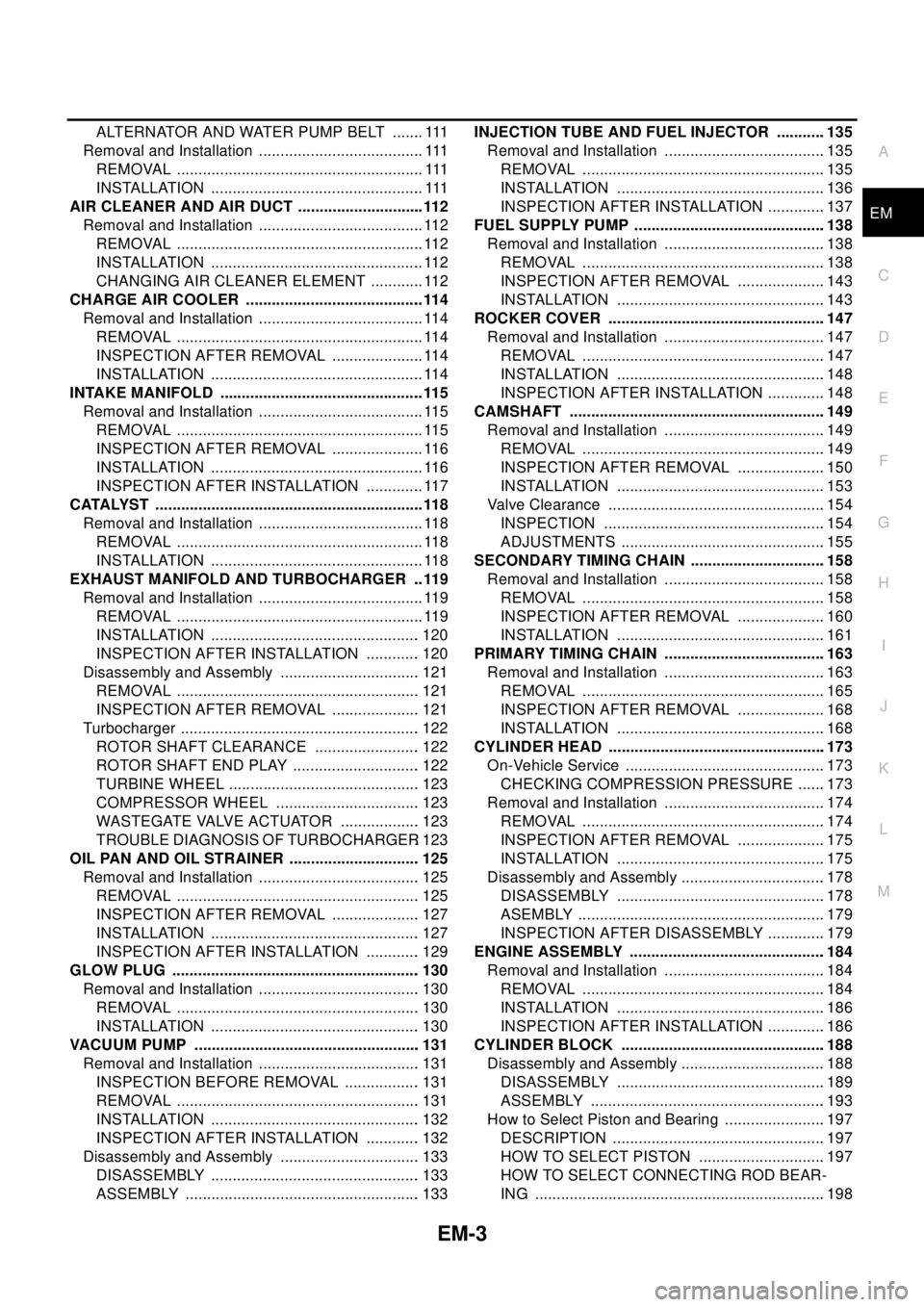
EM-3
C
D
E
F
G
H
I
J
K
L
M
EMA ALTERNATOR AND WATER PUMP BELT ....... . 111
Removal and Installation ...................................... . 111
REMOVAL ......................................................... . 111
INSTALLATION ................................................. . 111
AIR CLEANER AND AIR DUCT .............................. 112
Removal and Installation ....................................... 112
REMOVAL .......................................................... 112
INSTALLATION .................................................. 112
CHANGING AIR CLEANER ELEMENT ............. 112
CHARGE AIR COOLER .......................................... 114
Removal and Installation ....................................... 114
REMOVAL .......................................................... 114
INSPECTION AFTER REMOVAL ...................... 114
INSTALLATION .................................................. 114
INTAKE MANIFOLD ................................................ 115
Removal and Installation ....................................... 115
REMOVAL .......................................................... 115
INSPECTION AFTER REMOVAL ...................... 116
INSTALLATION .................................................. 116
INSPECTION AFTER INSTALLATION .............. 117
CATALYST ............................................................... 118
Removal and Installation ....................................... 118
REMOVAL .......................................................... 118
INSTALLATION .................................................. 118
EXHAUST MANIFOLD AND TURBOCHARGER ... 119
Removal and Installation ....................................... 119
REMOVAL .......................................................... 119
INSTALLATION ................................................. 120
INSPECTION AFTER INSTALLATION ............. 120
Disassembly and Assembly ................................. 121
REMOVAL ......................................................... 121
INSPECTION AFTER REMOVAL ..................... 121
Turbocharger ........................................................ 122
ROTOR SHAFT CLEARANCE ......................... 122
ROTOR SHAFT END PLAY .............................. 122
TURBINE WHEEL ............................................. 123
COMPRESSOR WHEEL .................................. 123
WASTEGATE VALVE ACTUATOR ................... 123
TROUBLE DIAGNOSIS OF TURBOCHARGER. 123
OIL PAN AND OIL STRAINER ............................... 125
Removal and Installation ...................................... 125
REMOVAL ......................................................... 125
INSPECTION AFTER REMOVAL ..................... 127
INSTALLATION ................................................. 127
INSPECTION AFTER INSTALLATION ............. 129
GLOW PLUG .......................................................... 130
Removal and Installation ...................................... 130
REMOVAL ......................................................... 130
INSTALLATION ................................................. 130
VACUUM PUMP ..................................................... 131
Removal and Installation ...................................... 131
INSPECTION BEFORE REMOVAL .................. 131
REMOVAL ......................................................... 131
INSTALLATION ................................................. 132
INSPECTION AFTER INSTALLATION ............. 132
Disassembly and Assembly ................................. 133
DISASSEMBLY ................................................. 133
ASSEMBLY ....................................................... 133INJECTION TUBE AND FUEL INJECTOR ............135
Removal and Installation ......................................135
REMOVAL .........................................................135
INSTALLATION .................................................136
INSPECTION AFTER INSTALLATION ..............137
FUEL SUPPLY PUMP .............................................138
Removal and Installation ......................................138
REMOVAL .........................................................138
INSPECTION AFTER REMOVAL .....................143
INSTALLATION .................................................143
ROCKER COVER ...................................................147
Removal and Installation ......................................147
REMOVAL .........................................................147
INSTALLATION .................................................148
INSPECTION AFTER INSTALLATION ..............148
CAMSHAFT ............................................................149
Removal and Installation ......................................149
REMOVAL .........................................................149
INSPECTION AFTER REMOVAL .....................150
INSTALLATION .................................................153
Valve Clearance ...................................................154
INSPECTION ....................................................154
ADJUSTMENTS ................................................155
SECONDARY TIMING CHAIN ................................158
Removal and Installation ......................................158
REMOVAL .........................................................158
INSPECTION AFTER REMOVAL .....................160
INSTALLATION .................................................161
PRIMARY TIMING CHAIN ......................................163
Removal and Installation ......................................163
REMOVAL .........................................................165
INSPECTION AFTER REMOVAL .....................168
INSTALLATION .................................................168
CYLINDER HEAD ...................................................173
On-Vehicle Service ...............................................173
CHECKING COMPRESSION PRESSURE .......173
Removal and Installation ......................................174
REMOVAL .........................................................174
INSPECTION AFTER REMOVAL .....................175
INSTALLATION .................................................175
Disassembly and Assembly ..................................178
DISASSEMBLY .................................................178
ASEMBLY ..........................................................179
INSPECTION AFTER DISASSEMBLY ..............179
ENGINE ASSEMBLY ..............................................184
Removal and Installation ......................................184
REMOVAL .........................................................184
INSTALLATION .................................................186
INSPECTION AFTER INSTALLATION ..............186
CYLINDER BLOCK ................................................188
Disassembly and Assembly ..................................188
DISASSEMBLY .................................................189
ASSEMBLY .......................................................193
How to Select Piston and Bearing ........................197
DESCRIPTION ..................................................197
HOW TO SELECT PISTON ..............................197
HOW TO SELECT CONNECTING ROD BEAR-
ING ....................................................................198
Page 1982 of 3066
![NISSAN X-TRAIL 2003 Electronic Repair Manual EM-12
[QR20DE]
NOISE, VIBRATION, AND HARSHNESS (NVH) TROUBLESHOOTING
Use the Chart Below to Help You Find the Cause of the Symptom.
EBS009QN
1. Locate the area where noise occurs.
2. Confirm the type NISSAN X-TRAIL 2003 Electronic Repair Manual EM-12
[QR20DE]
NOISE, VIBRATION, AND HARSHNESS (NVH) TROUBLESHOOTING
Use the Chart Below to Help You Find the Cause of the Symptom.
EBS009QN
1. Locate the area where noise occurs.
2. Confirm the type](/manual-img/5/57402/w960_57402-1981.png)
EM-12
[QR20DE]
NOISE, VIBRATION, AND HARSHNESS (NVH) TROUBLESHOOTING
Use the Chart Below to Help You Find the Cause of the Symptom.
EBS009QN
1. Locate the area where noise occurs.
2. Confirm the type of noise.
3. Specify the operating condition of engine.
4. Check specified noise source.
If necessary, repair or replace these parts.
A: Closely related B: Related C: Sometimes related —: Not relatedLocation
of noiseType of
noiseOperating condition of engine
Source of
noiseCheck itemRefer-
ence page Before
warm-
upAfter
warm-
upWhen
start-
ingWhen
idlingWhen
racingWhile
driving
To p o f
engine
Rocker
cover
Cylinder
headTick ing or
clickingCA—AB—Tappet
noiseValve clearanceEM-40
Rattle C A — A B CCamshaft
bearing
noiseCamshaft journal clear-
ance
Camshaft runoutEM-38EM-38
Crank-
shaft pul-
ley
Cylinder
block
(Side of
engine)
Oil panSlap or
knock—A—BB—Piston pin
noisePiston and piston pin
clearance
Connecting rod bush-
ing clearanceEM-83
EM-83
Slap or
rapA ——BBAPiston
slap noisePiston-to-bore clear-
ance
Piston ring side clear-
ance
Piston ring end gap
Connecting rod bend
and torsionEM-82EM-82
EM-82
EM-82
Knock A B CBBBConnect-
ing rod
bearing
noiseConnecting rod bush-
ing clearance (Small
end)
Connecting rod bear-
ing clearance (Big end)EM-83EM-83
Knock A B — A B CMain
bearing
noiseMain bearing oil clear-
ance
Crankshaft runoutEM-88EM-87
Front of
engine
Timin g
chain
coverTa p p i n g o r
tickingA A —BBBTiming
chain and
chain ten-
sioner
noiseTiming chain cracks
and wear
Timing chain tensioner
operationEM-47
EM-43
Front of
engineSqueak-
ing or fizz-
ingAB—B—CDrive belts
(Sticking
or slip-
ping)Drive belts deflection
EM-13
CreakingA B ABABDrive belts
(Slipping)Idler pulley bearing
operation
Squall
CreakA B —BABWater
pump
noiseWater pump operationCO-19,
"WATER
PUMP"
Page 2014 of 3066
![NISSAN X-TRAIL 2003 Electronic Repair Manual EM-44
[QR20DE]
TIMING CHAIN
CAUTION:
Apply new engine oil to parts marked in illustration before installation.
REMOVAL
1. Remove the parts listed below.
lEngine hood
lUndercover
lPCV hose
lIgnition co NISSAN X-TRAIL 2003 Electronic Repair Manual EM-44
[QR20DE]
TIMING CHAIN
CAUTION:
Apply new engine oil to parts marked in illustration before installation.
REMOVAL
1. Remove the parts listed below.
lEngine hood
lUndercover
lPCV hose
lIgnition co](/manual-img/5/57402/w960_57402-2013.png)
EM-44
[QR20DE]
TIMING CHAIN
CAUTION:
Apply new engine oil to parts marked in illustration before installation.
REMOVAL
1. Remove the parts listed below.
lEngine hood
lUndercover
lPCV hose
lIgnition coil; Refer toEM-27, "Removal and Installation".
lRocker cover; Refer toEM-31, "Removal and Installation".
lEngine coolant reservoir tank
lAuxiliary drive belt; Refer toEM-13, "Removal and Installation".
lAlternator
lAuxiliary drive belt auto-tensioner; Refer toEM-14, "Removal and Installation of Auxiliary Drive Belt
Auto- tensioner".
lExhaust front tube; Refer toEX-2, "EXHAUST SYSTEM".
2. Remove A/C compressor from engine. Temporarily secure A/C compressor to vehicle side with a rope to
avoid putting a load on them.
3. Remove bracket mounting bolts for fixing A/C piping on right strut housing and exhaust manifold cover.
Doing so simplifies moving.
4. Move power steering pump with piping connected, and secure it to vehicle side temporarily.
5. Pull power steering reservoir tank out of brackets to move power steering piping.
CAUTION:
lTo avoid power steering fluid leakage, temporarily fix reservoir tank vertically.
6. Suspend engine with a hoist, and support the engine posture.
For installation of engine slingers, refer toEM-61, "
ENGINE ASSEMBLY"
7. Remove RH engine mount insulator.
8. Remove center member and rear engine mounting bracket.
9. Drain engine oil.
10. Remove oil pan upper and lower, and oil strainer. Refer toEM-24, "
Removal and Installation".
11. Remove Intake valve timing control cover.
a. Loosen bolts in reverse order shown in the figure.
b. Remove the cover using Tool (Seal cutter).
12. Pull chain guide between camshaft sprockets out through front
cover.
13. Set No.1 cylinder at TDC on its compression stroke with the fol-
lowing procedure.
a. Rotate crankshaft pulley clockwise and align mating marks to
timid indicator on front cover.
KBIA0085E
KBIA0190E