Page 2198 of 3066
FAX-2
PRECAUTIONS
PRECAUTIONS
PFP:00001
CautionEDS0005P
Observe the following precautions when disassembling and servicing drive shaft.
lThe wheel joint cannot be disassembled. Do not attempt to disassemble it.
lPerform work in a location which is as dust-free and dirt-free as possible.
lBefore disassembling and servicing, clean the outside of parts.
lThe disassembly and service location must be clean. Care must be taken to prevent parts from becoming
dirty and to prevent the entry of foreign objects.
lDisassembled parts must be carefully reassembled in the correct order. If work is interrupted, a clean
cover must be placed over parts.
lPaper shop cloths must be used. Fabric shop cloths must not be used because of the danger of lint adher-
ing to parts.
lDisassembled parts (except for rubber parts) should be cleaned with kerosene which shall be removed by
blowing with air or wiping with paper shop cloths.
Precautions for Brake SystemEDS0 00 I0
lWhen installing rubber parts, final tightening must be carried out
under unladen condition* with tires on ground.
*: Fuel, radiator coolant and engine oil full. Spare tire, jack,
hand tools and mats in designated positions.
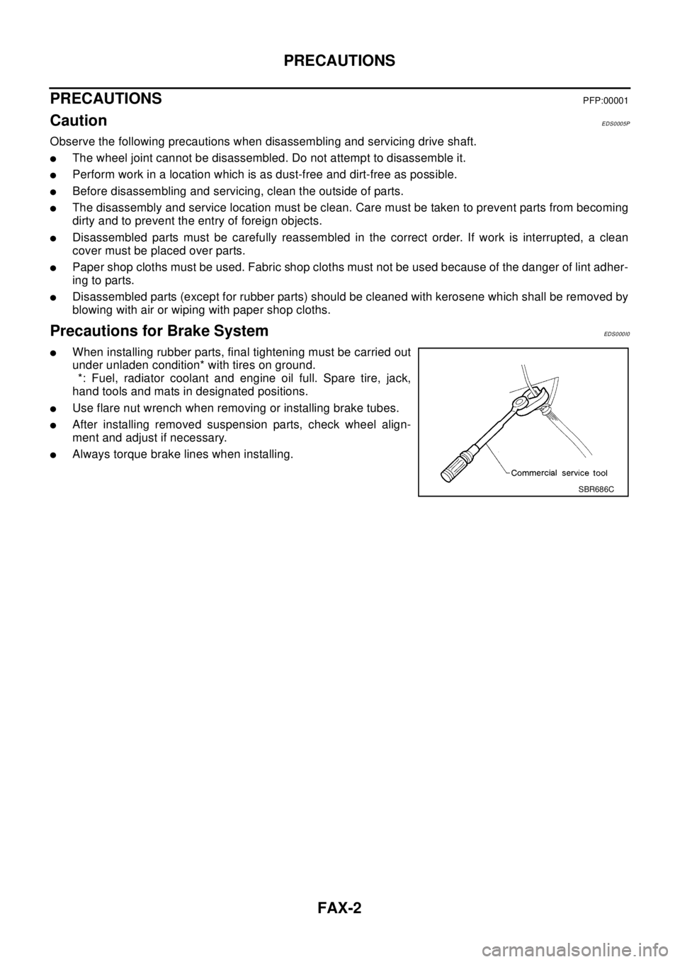
lUse flare nut wrench when removing or installing brake tubes.
lAfter installing removed suspension parts, check wheel align-
ment and adjust if necessary.
lAlways torque brake lines when installing.
SBR686C
Page 2241 of 3066
FSU-2
PRECAUTIONS
PRECAUTIONS
PFP:00001
CautionEES0006Z
lWhen installing rubber bushings, final tightening must be carried out under unladen conditions with tires
on flat, level ground. Oil will shorten the life of rubber bushings. Be sure to wipe off any spilled oil.
l“Unladen condition” means that fuel, coolant and lubricant are full and ready for drive. However, spare tire,
jack, and hand tools should be unloaded.
lAfter installing the removed suspension parts, always check wheel alignment and adjust if necessary.
lReplace the caulking nut with a new one. Install a new nut without wiping the oil off before tightening.
Precautions for Brake SystemEES000JA
lWhen installing rubber parts, final tightening must be carried out
under unladen condition* with tires on ground.
*: Fuel, radiator coolant and engine oil full. Spare tire, jack,
hand tools and mats in designated positions.
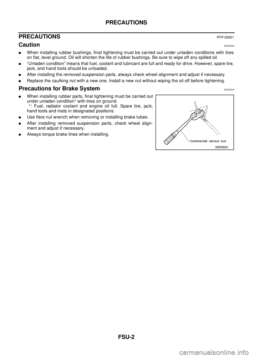
lUse flare nut wrench when removing or installing brake tubes.
lAfter installing removed suspension parts, check wheel align-
ment and adjust if necessary.
lAlways torque brake lines when installing.
SBR686C
Page 2245 of 3066
FSU-6
FRONT SUSPENSION ASSEMBLY
On-Vehicle Inspection and Service
EES00072
LOOSENESS, BACKLASH AND DAMAGE OF MOUNTING PARTS AND CONNECTIONS
Lift vehicle and inspect the following:
lCheck mounting point of each component for looseness, backlash and damage.
lCheck lower ball joint end play.
1. Attach a dial gauge so that the contact rests on the brake caliper.
2. Set front wheels in a straight-ahead position. Do not depress brake pedal.
3. Measure axial endplay by placing an iron pry bar or something similar between transverse link and steer-
ing knuckle.
CAUTION:
Be careful not to damage ball joint boot.
4. If axial endplay is outside the standard, remove transverse link and check lower ball joint.
Wheel AlignmentEES00073
DESCRIPTION
lMeasure wheel alignment under unladen conditions. “Unladen conditions” means that fuel, coolant, and
lubricant are full. However, spare tire, jack, and hand tools should be unloaded.
PRELIMINARY INSPECTION
1. Check the tires for improper air pressure and wear.
2. Check road wheels for runout.
3. Check wheel bearing axial endplay.
4. Check lower ball joint axial endplay.
5. Check strut operation.
6. Check each mounting point of axle and suspension for looseness and deformation.
7. Check each link and arm for cracks, deformation, and other damage.
8. Check the vehicle posture.
INSPECTION OF CAMBER, CASTER, AND KINGPIN INCLINATION ANGLES
lCamber, caster, and kingpin inclination angles cannot be adjusted.
lBefore inspection, mount front wheels onto turning radius gauge. Mount rear wheels onto a stand that has
same height so the vehicle will remain horizontal.
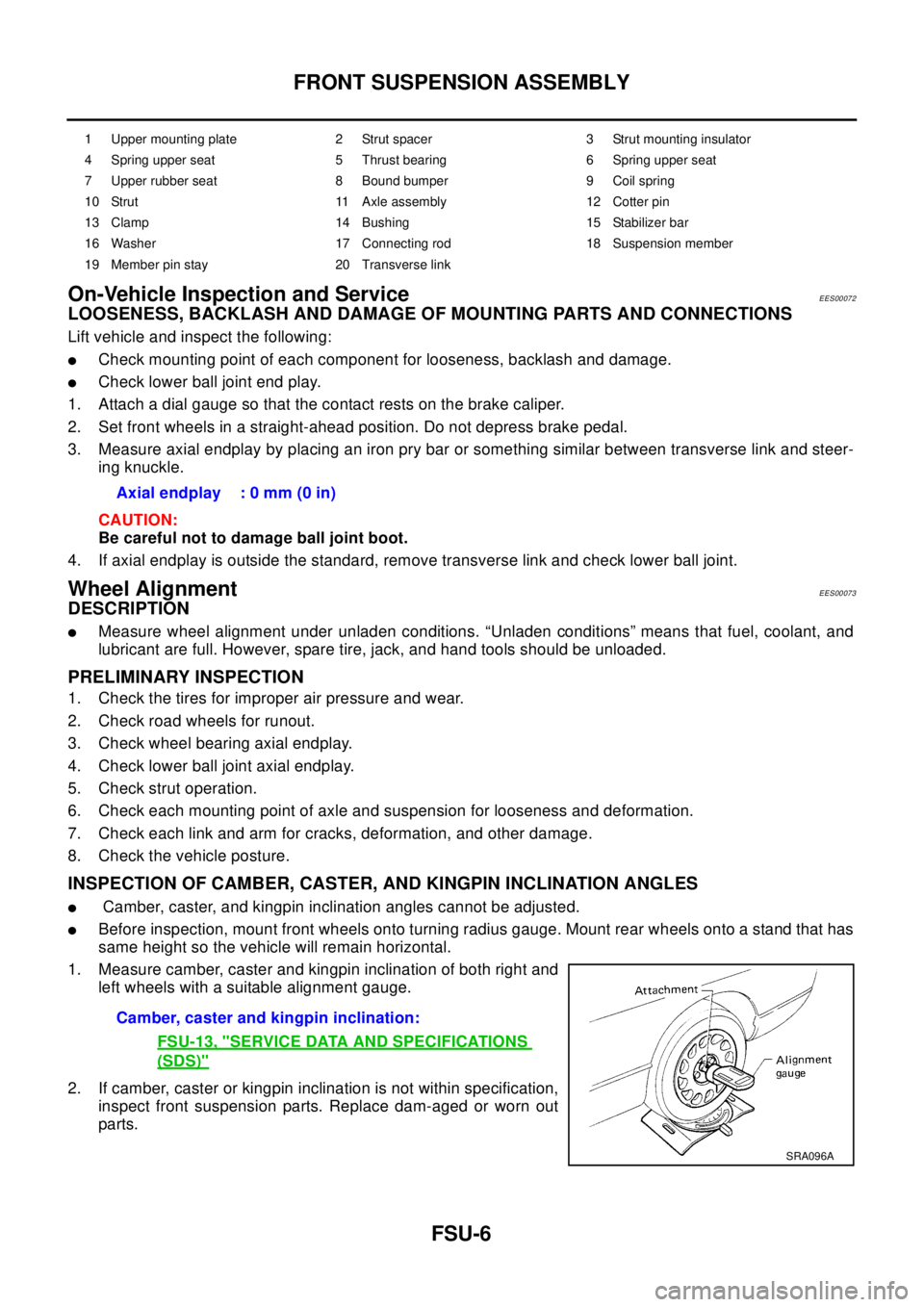
1. Measure camber, caster and kingpin inclination of both right and
left wheels with a suitable alignment gauge.
2. If camber, caster or kingpin inclination is not within specification,
inspect front suspension parts. Replace dam-aged or worn out
parts.
1 Upper mounting plate 2 Strut spacer 3 Strut mounting insulator
4 Spring upper seat 5 Thrust bearing 6 Spring upper seat
7 Upper rubber seat 8 Bound bumper 9 Coil spring
10 Strut 11 Axle assembly 12 Cotter pin
13 Clamp 14 Bushing 15 Stabilizer bar
16 Washer 17 Connecting rod 18 Suspension member
19 Member pin stay 20 Transverse link
Axial endplay : 0 mm (0 in)
Camber, caster and kingpin inclination:
FSU-13, "
SERVICE DATA AND SPECIFICATIONS
(SDS)"
SRA096A
Page 2252 of 3066
SERVICE DATA AND SPECIFICATIONS (SDS)
FSU-13
C
D
F
G
H
I
J
K
L
MA
B
FSU
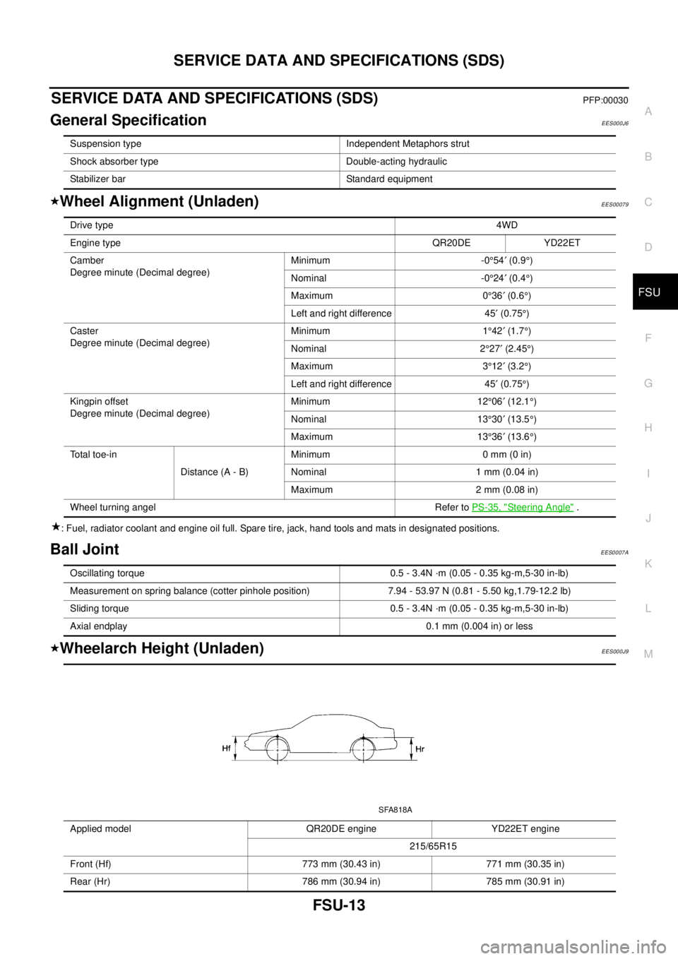
SERVICE DATA AND SPECIFICATIONS (SDS)PFP:00030
General SpecificationEES000J6
Wheel Alignment (Unladen)EES00079
: Fuel, radiator coolant and engine oil full. Spare tire, jack, hand tools and mats in designated positions.
Ball JointEES0007A
Wheelarch Height (Unladen)EES000J9
Suspension type Independent Metaphors strut
Shock absorber type Double-acting hydraulic
Stabilizer bar Standard equipment
Drive type4WD
Engine typeQR20DE YD22ET
Camber
Degree minute (Decimal degree)Minimum -0°54¢(0.9°)
Nominal -0°24¢(0.4°)
Maximum 0°36¢(0.6°)
Left and right difference 45¢(0.75°)
Caster
Degree minute (Decimal degree)Minimum 1°42¢(1.7°)
Nominal 2°27¢(2.45°)
Maximum 3°12¢(3.2°)
Left and right difference 45¢(0.75°)
Kingpin offset
Degree minute (Decimal degree)Minimum 12°06¢(12.1°)
Nominal 13°30¢(13.5°)
Maximum 13°36¢(13.6°)
To t a l t o e - i n
Distance (A - B)Minimum 0 mm (0 in)
Nominal 1 mm (0.04 in)
Maximum 2 mm (0.08 in)
Wheel turning angel Refer toPS-35, "
Steering Angle".
Oscillating torque 0.5 - 3.4N ·m (0.05 - 0.35 kg-m,5-30 in-lb)
Measurement on spring balance (cotter pinhole position) 7.94 - 53.97 N (0.81 - 5.50 kg,1.79-12.2 lb)
Sliding torque 0.5 - 3.4N ·m (0.05 - 0.35 kg-m,5-30 in-lb)
Axial endplay 0.1 mm (0.004 in) or less
Applied model QR20DE engine YD22ET engine
215/65R15
Front (Hf) 773 mm (30.43 in) 771 mm (30.35 in)
Rear (Hr) 786 mm (30.94 in) 785 mm (30.91 in)
SFA818A
Page 2253 of 3066
FSU-14
SERVICE DATA AND SPECIFICATIONS (SDS)
: Fuel, radiator coolant and engine oil full. Spare tire, jack, hand tools and mats in designated positions.
Page 2299 of 3066
GI-46
IDENTIFICATION INFORMATION
MANUAL TRANSAXLE NUMBER
DimensionsEAS000GF
Unit: mm(in)
Wheels & TiresEAS000GG
PAIA0010E
Overall length 4,510
Overall width 1,765
Overall height 1,675 (Standard), 1,750 (With Rear spoiler)
Front tread 1,530
Rear tread 1,530
Wheelbase 2,625
Conventional Spare
Road wheel/offset mm (in)15´6JJ Steel/40 (1.57)
16´6.5JJ Steel/Aluminum/40 (1.57)Conventional
Tire size215/70 R15
215/65 R16Conventional
Page 2496 of 3066
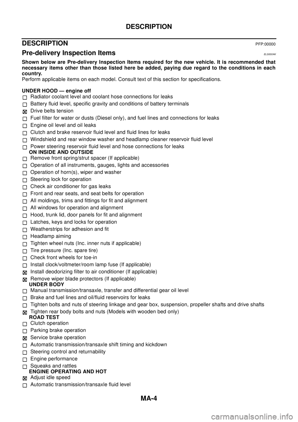
MA-4
DESCRIPTION
DESCRIPTION
PFP:00000
Pre-delivery Inspection ItemsELS000AK
Shown below are Pre-delivery Inspection Items required for the new vehicle. It is recommended that
necessary items other than those listed here be added, paying due regard to the conditions in each
country.
Perform applicable items on each model. Consult text of this section for specifications.
UNDER HOOD — engine off
Radiator coolant level and coolant hose connections for leaks
Battery fluid level, specific gravity and conditions of battery terminals
Drive belts tension
Fuel filter for water or dusts (Diesel only), and fuel lines and connections for leaks
Engine oil level and oil leaks
Clutch and brake reservoir fluid level and fluid lines for leaks
Windshield and rear window washer and headlamp cleaner reservoir fluid level
Power steering reservoir fluid level and hose connections for leaks
ON INSIDE AND OUTSIDE
Remove front spring/strut spacer (If applicable)
Operation of all instruments, gauges, lights and accessories
Operation of horn(s), wiper and washer
Steering lock for operation
Check air conditioner for gas leaks
Front and rear seats, and seat belts for operation
All moldings, trims and fittings for fit and alignment
All windows for operation and alignment
Hood, trunk lid, door panels for fit and alignment
Latches, keys and locks for operation
Weatherstrips for adhesion and fit
Headlamp aiming
Tighten wheel nuts (Inc. inner nuts if applicable)
Tire pressure (Inc. spare tire)
Check front wheels for toe-in
Install clock/voltmeter/room lamp fuse (If applicable)
Install deodorizing filter to air conditioner (If applicable)
Remove wiper blade protectors (If applicable)
UNDER BODY
Manual transmission/transaxle, transfer and differential gear oil level
Brake and fuel lines and oil/fluid reservoirs for leaks
Tighten bolts and nuts of steering linkage and gear box, suspension, propeller shafts and drive shafts
Tighten rear body bolts and nuts (Models with wooden bed only)
ROAD TEST
Clutch operation
Parking brake operation
Service brake operation
Automatic transmission/transaxle shift timing and kickdown
Steering control and returnability
Engine performance
Squeaks and rattles
ENGINE OPERATING AND HOT
Adjust idle speed
Automatic transmission/transaxle fluid level
Page 2497 of 3066
DESCRIPTION
MA-5
C
D
E
F
G
H
I
J
K
MA
B
MA
Engine idling and stop knob operation (Diesel only)
FINAL INSPECTION
Install necessary parts (outside mirror, wheel covers, seat belts, mat, carpet or mud flaps)
Inspect for interior and exterior metal and paint damage
Check for spare tire, jack, tools (wheel chock), and literature
Wash, clean interior and exterior
: Not applicable to this model