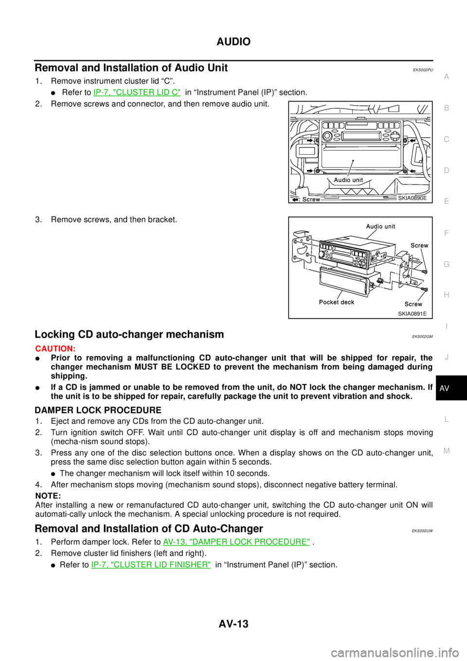
2003 NISSAN X-TRAIL CD changer
[x] Cancel search: CD changerPage 723 of 3066

AV-1
AUDIO, VISUAL & TELEPHONE SYSTEM
K ELECTRICAL
CONTENTS
C
D
E
F
G
H
I
J
L
M
SECTION
A
B
AV
AUDIO, VISUAL & TELEPHONE SYSTEM
PRECAUTIONS .......................................................... 2
Precautions for Supplemental Restraint System
(SRS) “AIR BAG” and “SEAT BELT PRE-TEN-
SIONER” .................................................................. 2
Wiring Diagrams and Trouble Diagnosis .................. 2
AUDIO ......................................................................... 3
System Description .................................................. 3
NATS AUDIO LINK ............................................... 3
SPEED DEPENDENT VOLUME CONTROL ........ 4
PERSONAL AUDIO SETTINGS ........................... 4
Schematic ................................................................ 5
Wiring Diagram —AUDIO— ..................................... 6
LHD MODELS ....................................................... 6
RHD MODELS ...................................................... 9Trouble Diagnoses ................................................. 12
AUDIO UNIT ........................................................ 12
Inspection ............................................................... 12
AUDIO UNIT ........................................................ 12
ANTENNA ........................................................... 12
Removal and Installation of Audio Unit ................... 13
Locking CD auto-changer mechanism ................... 13
DAMPER LOCK PROCEDURE .......................... 13
Removal and Installation of CD Auto-Changer ....... 13
Removal and Installation of Speakers .................... 14
Removal and Installation of Tweeters ..................... 14
AUDIO ANTENNA .................................................... 15
Antenna Route ........................................................ 15
Removal and Installation of Roof Antenna ............. 15
Page 725 of 3066

AUDIO
AV-3
C
D
E
F
G
H
I
J
L
MA
B
AV
AUDIOP F P : 2 8 111
System DescriptionEKS002F2
Refer to Owner's Manual for audio system operating instructions.
Power is supplied at all times
lthrough 15A fuse (No. 32, located in the fusible link and fuse block)
lto audio unit terminal 3
lto CD auto changer terminal 32.
With the ignition switch in the ACC or ON position, power is supplied
lthrough 10A fuse [No. 4, located in the fuse block (J/B)]
lto audio unit terminal 6,
lto CD auto changer terminal 36
Ground is supplied through the case of the audio unit.
Audio signals are supplied
lthrough audio unit terminals 5, 7, 9, 10, 11, 13, 15, 16
lto terminals 1 and 2 of front door speaker LH and RH,
lto terminals 1 and 2 of rear door speaker LH and RH and
lto terminals 1 and 2 of tweeter LH and RH (with 6 speakers)
NATS AUDIO LINK
Description
The link with the NATS IMMU implies that the audio unit can basically only be operated if connected to the
matching NATS IMMU to which the audio unit was initially fitted on the production line.
Since radio operation is impossible after the link with the NATS is disrupted theft of the audio unit is basically
useless since special equipment is required to reset the audio unit.
Initialization process for audio units that are linked to the NATS IMMU
New audio units will be delivered to the factories in the “NEW” state, i.e. ready to be linked with the vehicle's
NATS. When the audio unit in “NEW” state is first switched on at the factory, it will start up communication with
the vehicle's immobilizer control unit (IMMU) and send a code (the “audio unit Code”) to the IMMU. The IMMU
will then store this code, which is unique to each audio unit, in its (permanent) memory.
Upon receipt of the code by the IMMU, the NATS will confirm correct receipt of the audio unit code to the audio
unit. Hereafter, the audio unit will operate as normal.
During the initialization process, “NEW” is displayed on the audio unit display. Normally though, communica-
tion between audio unit and IMMU takes such a short time (300 ms) that the audio unit seems to switch on
directly without showing “NEW” on its display.
Normal operation
Each time the audio unit is switched on afterwards, the audio unit code will be verified between the audio unit
and the NATS before the audio unit becomes operational. During the code verification process, “WAIT” is
shown on the audio unit display. Again, the communication takes such a short time (300 ms) that the audio
unit seems to switch on directly without showing “WAIT” on its display.
When the radio is locked
In case of a audio unit being linked with the vehicle's NATS (immobilizer system), disconnection of the link
between the audio unit and the IMMU will cause the audio unit to switch into the lock (“SECURE”) mode in
which the audio unit is fully inoperative. Hence, repair of the audio unit is basically impossible, unless the
audio unit is reset to the “NEW” state for which special decoding equipment is required.
Clarion has provided their authorized service representatives with so called “decoder boxes” which can bring
the audio unit back to the “NEW” state, enabling the audio unit to be switched on after which repair can be car-
ried out. Subsequently, when the repaired audio unit is delivered to the final user again, it will be in the “NEW”
state to enable re-linking the audio unit to the vehicle's immobilizer system. As a result of the above, repair of
the audio unit can only be done by an authorized Clarion representative (when the owner of the vehicle
requests repair and can show personal identification).
Page 735 of 3066

AUDIO
AV-13
C
D
E
F
G
H
I
J
L
MA
B
AV
RemovalandInstallationofAudioUnitEKS002PU
1. Remove instrument cluster lid “C”.
lRefer toIP-7, "CLUSTER LID C"in “Instrument Panel (IP)” section.
2. Remove screws and connector, and then remove audio unit.
3. Remove screws, and then bracket.
Locking CD auto-changer mechanismEKS002GM
CAUTION:
lPrior to removing a malfunctioning CD auto-changer unit that will be shipped for repair, the
changer mechanism MUST BE LOCKED to prevent the mechanism from being damaged during
shipping.
lIf a CD is jammed or unable to be removed from the unit, do NOT lock the changer mechanism. If
the unit is to be shipped for repair, carefully package the unit to prevent vibration and shock.
DAMPER LOCK PROCEDURE
1. Eject and remove any CDs from the CD auto-changer unit.
2. Turn ignition switch OFF. Wait until CD auto-changer unit display is off and mechanism stops moving
(mecha-nism sound stops).
3. Press any one of the disc selection buttons once. When a display shows on the CD auto-changer unit,
press the same disc selection button again within 5 seconds.
lThe changer mechanism will lock itself within 10 seconds.
4. After mechanism stops moving (mechanism sound stops), disconnect negative battery terminal.
NOTE:
After installing a new or remanufactured CD auto-changer unit, switching the CD auto-changer unit ON will
automati-cally unlock the mechanism. A special unlocking procedure is not required.
Removal and Installation of CD Auto-ChangerEKS002UW
1. Perform damper lock. Refer toAV- 1 3 , "DAMPER LOCK PROCEDURE".
2. Remove cluster lid finishers (left and right).
lRefer toIP-7, "CLUSTER LID FINISHER"in “Instrument Panel (IP)” section.
SKIA0890E
SKIA0891E
Page 736 of 3066

AV-14
AUDIO
3. Remove screws, and then remove CD auto-changer with
bracket attached.
4. Remove screws, and then bracket.
Removal and Installation of SpeakersEKS002PV
1. Remove door finisher.
lRefer toEI-23, "DOOR FINISHER"in “Exterior/Interior (EI)”
section.
2. Remove speakers.
Removal and Installation of TweetersEKS002GO
1. Remove front speaker grille.
lRefer toIP-6, "FRONT SPEAKER GRILLE"in “Exterior/Inte-
rior (EI)” section.
2. Remove tweeters.
SKIA0892E
SKIA0893E
SKIA0001E
SKIA0002E
Page 2367 of 3066

IP-1
INSTRUMENT PANEL
IBODY
CONTENTS
C
D
E
F
G
H
J
K
L
M
SECTION
A
B
IP
INSTRUMENT PANEL
PRECAUTIONS .......................................................... 2
Precautions for Supplemental Restraint System
(SRS) “AIR BAG” and “SEAT BELT PRE-TEN-
SIONER” .................................................................. 2
Precautions .............................................................. 2
INSTRUMENT PANEL ASSEMBLY ........................... 3
Component Parts Drawing ....................................... 3
Removal and Installation .......................................... 5
TABLE OF WORK ITEM ....................................... 5
FRONT SPEAKER GRILLE .................................. 6
INSTRUMENT FINISHER ..................................... 6
CUP HOLDER ....................................................... 6
CLUSTER LID A ................................................... 6
COMBINATION METER ....................................... 6
GPS ANTENNA .................................................... 6
POCKET ............................................................... 6
STEERING COLUMN COVER ............................. 6
INSTRUMENT LOWER DRIVER PANEL ............. 7
MIRROR CONTROL SWITCH .............................. 7CLUSTER LID C ................................................... 7
AUDIO UNIT AND POCKET ................................. 7
CLUSTER LID FINISHER ..................................... 7
A/T OR M/T FINISHER ......................................... 8
CENTER CONSOLE ............................................. 8
CD AUTO–CHANGER AND POCKET .................. 8
HEATER CONTROL FINISHER ............................ 8
HEATER CONTROLLER ....................................... 8
LOWER INSTRUMENT COVER ........................... 8
INSTRUMENT LOWER CENTER PANEL ............ 8
GLOVE BOX ......................................................... 9
LOWER INSTRUMENT PANEL ............................ 9
GLOVE BOX COVER ............................................ 9
FRONT PASSENGER AIR BAG MODULE ........... 9
INSTRUMENT MASK ............................................ 9
FRONT PILLAR GARNISH ................................... 9
INSTRUMENT PANEL .......................................... 9
Disassembly and Assembly .................................... 10
CONSOLE BOX ASSEMBLY .............................. 10
Page 2370 of 3066

IP-4
INSTRUMENT PANEL ASSEMBLY
1 Front passenger air bag module 2 Front speaker grille (left) 3 Front side speaker (left)
4 Cup holder (left) 5 Instrument finisher B 6 Combination meter
7 Instrument mask (left) 8 GPS antenna 9 Instrument mask (right)
10 Instrument cluster lid A 11 Pocket 12 Front speaker grille (right)
13 Front side speaker (right) 14 Cup holder (right) 15 Mirror control switch
16 Instrument panel & pad 17 Instrument reinforcement 18 Audio unit and pocket
19 Glove box cover 20 Lower instrument panel 21 Glove box pin
22 Glove box 23 Cluster lid C 24 Instrument finisher A
25 Instrument lower driver panel 26 Column cover, key cylinder escutcheon 27 Cluster lid finisher (right)
28 Heater control finisher 29 CD auto–changer and pocket 30 instrument lower center panel
31 Lower instrument cover 32 Cluster lid finisher (left) 33 Center console
34 A/T or M/T finisher 35 Console mask 36 Seal case (inner case)
Page 2371 of 3066
![NISSAN X-TRAIL 2003 Electronic Repair Manual INSTRUMENT PANEL ASSEMBLY
IP-5
C
D
E
F
G
H
J
K
L
MA
B
IP
Removal and InstallationEIS0 00 NI
TA B L E O F W O R K I T E M
[ ]: The number shows the removal order.
ComponentsInstrument
panelCombination
NISSAN X-TRAIL 2003 Electronic Repair Manual INSTRUMENT PANEL ASSEMBLY
IP-5
C
D
E
F
G
H
J
K
L
MA
B
IP
Removal and InstallationEIS0 00 NI
TA B L E O F W O R K I T E M
[ ]: The number shows the removal order.
ComponentsInstrument
panelCombination](/manual-img/5/57402/w960_57402-2370.png)
INSTRUMENT PANEL ASSEMBLY
IP-5
C
D
E
F
G
H
J
K
L
MA
B
IP
Removal and InstallationEIS0 00 NI
TA B L E O F W O R K I T E M
[ ]: The number shows the removal order.
ComponentsInstrument
panelCombination
meterNavigation
DisplayAudio
Console
Up Down
Front speaker grille [1]
Instrument finisher A, B [2] [1]
Cup holder [3]
Instrument cluster lid A [4] [2]
Combination meter [5] [3]
Pocket [6]
Key cylinder escutcheon and steer-
ing column cover[7]
Instrument lower driver panel [8]
Mirror control switch [9]
GPS antenna [10]
Cluster lid C [11] [1] [1]
Audio unit and pocket [12] [2] [2]
Cluster lid finisher [13] [1] [1]
Heater control finisher [14] [2]
CD auto–changer and pocket [15] [3]
Heater controller [16]
A/T(M/T,CVT) finisher [17] [2]
Console mask [18] [3]
Center console [19] [4]
Lower instrument cover [20]
instrument lower center panel [21]
Glove box [22]
Lower instrument panel [23]
Glove box cover [24]
Front passenger air bag module [25]
Instrument reinforcement [26]
Instrument mask [27]
Front pillar garnish [28]
Instrument panel [29]
Page 2374 of 3066

IP-8
INSTRUMENT PANEL ASSEMBLY
A/T OR M/T FINISHER
1. Insert a screwdriver, wrapped with a shop cloth, into cutout on
rear edge of finisher, and lift up to unfasten clip on rear edge of
side face.
2. Pull forward and remove.
CENTER CONSOLE
1. Remove screws.
2. Remove console mask, and remove center console.
CD AUTO–CHANGER AND POCKET
lRemove screws. Disconnect and remove connector.
NOTE:
During removal or installation, use shop cloth to protect surrounding area from damage.
HEATER CONTROL FINISHER
lInsert a screwdriver or similar tool, wrapped with a shop cloth,
into lower edge (clip position). Unfasten and remove clip.
HEATER CONTROLLER
lRemove mounting screws on heater controller.Disconnect remove connector.
LOWER INSTRUMENT COVER
lUnfasten resin clips, and pull toward vehicle rear.
INSTRUMENT LOWER CENTER PANEL
lUndo and remove screws.
SIIA0233E
SIIA0235E
SIIA0236E