2003 NISSAN X-TRAIL fuse box location
[x] Cancel search: fuse box locationPage 911 of 3066
![NISSAN X-TRAIL 2003 Electronic Repair Manual TROUBLE DIAGNOSIS
BRC-43
[4WD/ABS]
C
D
E
G
H
I
J
K
L
MA
B
BRC
3.CHECK CONTINUITY BETWEEN IGNITION SWITCH AND ABS WARNING LAMP.
lDisconnect 4WD/ABS control unit connector.
lCheck continuity between ign NISSAN X-TRAIL 2003 Electronic Repair Manual TROUBLE DIAGNOSIS
BRC-43
[4WD/ABS]
C
D
E
G
H
I
J
K
L
MA
B
BRC
3.CHECK CONTINUITY BETWEEN IGNITION SWITCH AND ABS WARNING LAMP.
lDisconnect 4WD/ABS control unit connector.
lCheck continuity between ign](/manual-img/5/57402/w960_57402-910.png)
TROUBLE DIAGNOSIS
BRC-43
[4WD/ABS]
C
D
E
G
H
I
J
K
L
MA
B
BRC
3.CHECK CONTINUITY BETWEEN IGNITION SWITCH AND ABS WARNING LAMP.
lDisconnect 4WD/ABS control unit connector.
lCheck continuity between ignition switch and 4WD/ABS control module terminal No. 4. (Open circuit
check)
Is inspection result OK?
YES >> Continuity exists. Connect 4WD/ABS control module connector, check again.
NO >> Continuity does not exist. Check ABS warning lamp path.
4.CHECK FUSE.
lCheck if Fuse No.8 is working normally.
Is the check result OK?
YES >> Repair or replace the harness in between 4WD/ABS control unit and IGN.
NO >> Replace the fuse and replace again.
lIf the figure of the monitor is with in±10% of the set value of E-TS solenoid electric current, 4WD/ABS C/
U is operating normally.Check for electric control coupling ASSY is required.
4WD warning lamp does not illuminate with ignition ON.EFS001BR
1.INSPECTION OF BLOWN 4WD WARNING LAMP BULB
lRemove glove box on the passenger side and disconnect the 4WD/ABS control unit connector.
lConfirm continuity between 4WD/ABS control unit connector terminals No. 3 (IGN) and No. 4 (ABS warn-
ing lamp).
Is inspection result OK?
YES >> GO TO 3. (Continuity exists.)
NO >>
lCheck 4WD warning lamp harness.
lRemove meter control module assembly and check for blown 4WD warning lamp bulb.
2.4WD ACTUATOR RELAY HARNESS INSPECTION
lOpen the hood and check that the 4WD relay is properly installed in the relay box.
lConfirm continuity between 4WD/ABS control unit connector terminals No. 7 (4WD warning lamp) and No.
104 (ground).
lConfirm continuity between 4WD/ABS control unit connector terminals No. 3 (IGN) and No. 18 (4WD
actuator relay).
Is inspection result OK?
YES >> Continuity exists. Connect 4WD/ABS control unit connector, check again.
NO >> Check ABS warning lamp harness.
4WD warning lamp does not go out several seconds after engine is started.
(Drive mode indicator lamp goes out.)
EFS001BS
1.USING CONSULT, PERFORM SELF-DIAGNOSIS.
4WD warning lamp does not go out several seconds after the engine is started. (Drive mode indicator lamp
goes out.)
Is inspection result OK?
YES >> No malfunction detected. Perform inspection again.
NO >>
lDetermine the location of the malfunction according to the result of self-diagnosis using CON-
SULT. (Malfunction is present in the 4WD system.)
lCONSULT-II does not display ABS -related trouble codes. Proceed to 2.
Page 2270 of 3066

HOW TO USE THIS MANUAL
GI-17
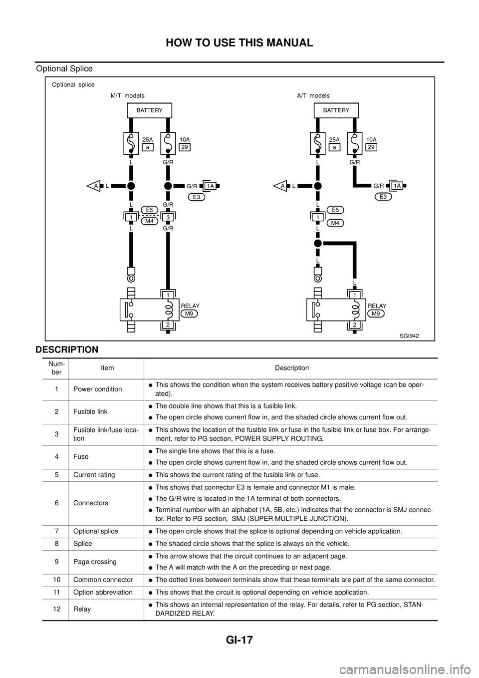
Optional Splice
DESCRIPTION
SGI942
Num-
berItem Description
1 Power condition
lThis shows the condition when the system receives battery positive voltage (can be oper-
ated).
2 Fusible link
lThe double line shows that this is a fusible link.
lThe open circle shows current flow in, and the shaded circle shows current flow out.
3Fusible link/fuse loca-
tion
lThis shows the location of the fusible link or fuse in the fusible link or fuse box. For arrange-
ment, refer to PG section, POWER SUPPLY ROUTING.
4Fuse
lThe single line shows that this is a fuse.
lThe open circle shows current flow in, and the shaded circle shows current flow out.
5 Current rating
lThis shows the current rating of the fusible link or fuse.
6 Connectors
lThis shows that connector E3 is female and connector M1 is male.
lThe G/R wire is located in the 1A terminal of both connectors.
lTerminal number with an alphabet (1A, 5B, etc.) indicates that the connector is SMJ connec-
tor. Refer to PG section, SMJ (SUPER MULTIPLE JUNCTION).
7 Optional splice
lThe open circle shows that the splice is optional depending on vehicle application.
8 Splice
lThe shaded circle shows that the splice is always on the vehicle.
9 Page crossing
lThis arrow shows that the circuit continues to an adjacent page.
lThe A will match with the A on the preceding or next page.
10 Common connector
lThe dotted lines between terminals show that these terminals are part of the same connector.
11 Option abbreviation
lThis shows that the circuit is optional depending on vehicle application.
12 Relay
lThis shows an internal representation of the relay. For details, refer to PG section, STAN-
DARDIZED RELAY.
Page 2312 of 3066

REAR WINDOW DEFOGGER
GW-9
C
D
E
F
G
H
J
K
L
MA
B
GW
REAR WINDOW DEFOGGERPFP:25350
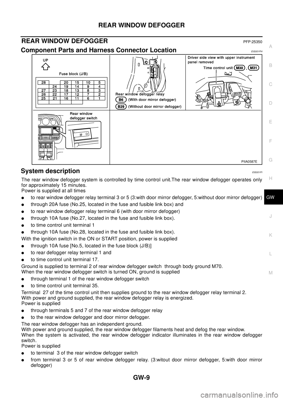
Component Parts and Harness Connector LocationEIS001PH
System descriptionEIS001PI
The rear window defogger system is controlled by time control unit.The rear window defogger operates only
for approximately 15 minutes.
Power is supplied at all times
lto rear window defogger relay terminal 3 or 5 (3:with door mirror defogger, 5:without door mirror defogger)
lthrough 20A fuse (No.25, located in the fuse and fusible link box) and
lto rear window defogger relay terminal 6 (with door mirror defogger)
lthrough 10A fuse (No.27, located in the fuse and fusible link box).
lto time control unit terminal 1
lthrough 10A fuse (No.28, located in the fuse and fusible link box).
With the ignition switch in the ON or START position, power is supplied
lthrough 10A fuse [No.5, located in the fuse block (J/B)]
lto rear defogger relay terminal 1 and
lto time control unit terminal 17.
Ground is supplied to terminal 2 of rear window defogger switch through body ground M70.
When the rear window defogger switch is turned ON, ground is supplied
lthrough terminal 1 of the rear window defogger switch
lto time control unit terminal 35.
Terminal 27 of the time control unit then supplies ground to the rear window defogger relay terminal 2.
With power and ground supplied, the rear window defogger relay is energized.
Power is supplied
lthrough terminals 5 and 7 of the rear window defogger relay
lto the rear window defogger and door mirror defogger.
The rear window defogger has an independent ground.
With power and ground supplied, the rear window defogger filaments heat and defog the rear window.
When the system is activated, the rear window defogger indicator illuminates in the rear window defogger
switch.
Power is supplied
lto terminal 3 of the rear window defogger switch
lfrom terminal 3 or 5 of rear window defogger relay. (3:witout door mirror defogger, 5:with door mirror
defogger)
PIIA0587E
Page 2323 of 3066

GW-20
POWER WINDOW SYSTEM
POWER WINDOW SYSTEM
PFP:25401
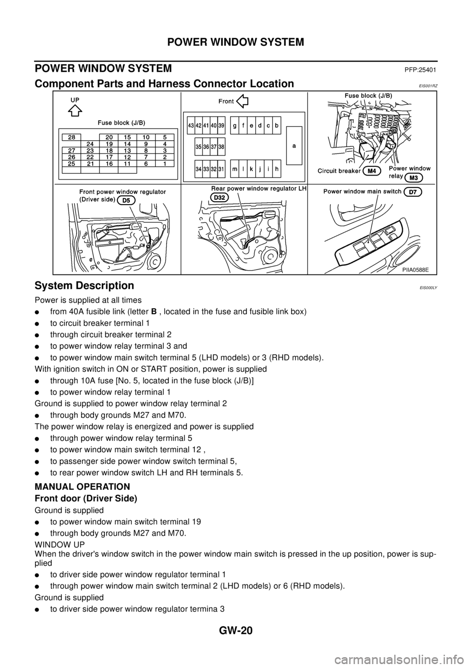
Component Parts and Harness Connector LocationEIS001RZ
System DescriptionEIS0 00 LY
Power is supplied at all times
lfrom 40A fusible link (letterB, located in the fuse and fusible link box)
lto circuit breaker terminal 1
lthrough circuit breaker terminal 2
lto power window relay terminal 3 and
lto power window main switch terminal 5 (LHD models) or 3 (RHD models).
With ignition switch in ON or START position, power is supplied
lthrough 10A fuse [No. 5, located in the fuse block (J/B)]
lto power window relay terminal 1
Ground is supplied to power window relay terminal 2
lthrough body grounds M27 and M70.
The power window relay is energized and power is supplied
lthrough power window relay terminal 5
lto power window main switch terminal 12 ,
lto passenger side power window switch terminal 5,
lto rear power window switch LH and RH terminals 5.
MANUAL OPERATION
Front door (Driver Side)
Ground is supplied
lto power window main switch terminal 19
lthrough body grounds M27 and M70.
WINDOW UP
When the driver's window switch in the power window main switch is pressed in the up position, power is sup-
plied
lto driver side power window regulator terminal 1
lthrough power window main switch terminal 2 (LHD models) or 6 (RHD models).
Ground is supplied
lto driver side power window regulator termina 3
PIIA0588E
Page 2677 of 3066

PG-1
POWER SUPPLY, GROUND & CIRCUIT ELEMENTS
K ELECTRICAL
CONTENTS
C
D
E
F
G
H
I
J
L
M
SECTION
A
B
PG
POWER SUPPLY, GROUND & CIRCUIT ELEMENTS
POWER SUPPLY ROUTING ...................................... 2
Schematic ................................................................ 2
Wiring Diagram — POWER — ................................. 3
BATTERY POWER SUPPLY — IGNITION SW.
IN ANY POSITION ................................................ 3
ACCESSORY POWER SUPPLY — IGNITION
SW. IN “ACC” OR “ON” ......................................... 7
IGNITION POWER SUPPLY — IGNITION SW.
IN “ON” AND/OR “START” .................................... 8
Fuse ....................................................................... 12
Fusible Link ............................................................ 12
Circuit Breaker ....................................................... 12
GROUND .................................................................. 13
Ground Distribution ................................................ 13
MAIN HARNESS/LHD MODELS ........................ 14
MAIN HARNESS/RHD MODELS ........................ 16
ENGINE ROOM HARNESS/LHD MODELS ....... 18
ENGINE ROOM HARNESS/RHD MODELS ....... 19
ENGINE ROOM HARNESS ................................ 20
ENGINE CONTROL HARNESS/GASOLINE
ENGINE MODELS .............................................. 21
ENGINE CONTROL HARNESS/DIESEL
ENGINE MODELS .............................................. 22
BODY HARNESS/LHD MODELS ....................... 23
BODY HARNESS/RHD MODELS ....................... 24
BODY NO.2 HARNESS/LHD MODELS .............. 25
BODY NO.2 HARNESS/RHD MODELS ............. 26
BODY NO.2 HARNESS ...................................... 27
BACK DOOR SUB HARNESS/REAR WINDOW
DEFOGGER HARNESS ..................................... 28
HARNESS ................................................................. 29
Harness Layout ...................................................... 29
HOW TO READ HARNESS LAYOUTS ............... 29
OUTLINE/LHD MODELS .................................... 30
OUTLINE/RHD MODELS .................................... 31
MAIN HARNESS/LHD MODELS ........................ 32
MAIN HARNESS/RHD MODELS ........................ 34ENGINE ROOM HARNESS/LHD MODELS ........ 36
ENGINE ROOM HARNESS/RHD MODELS ....... 41
ENGINE CONTROL HARNESS .......................... 46
BODY HARNESS/LHD MODELS ....................... 49
BODY HARNESS/RHD MODELS ....................... 50
BODY NO.2 HARNESS/LHD MODELS .............. 51
BODY NO.2 HARNESS/RHD MODELS .............. 52
ROOM LAMP HARNESS .................................... 53
FRONT DOOR HARNESS/LHD MODELS .......... 54
FRONT DOOR HARNESS/RHD MODELS ......... 56
REAR DOOR HARNESS .................................... 58
BACK DOOR HARNESS .................................... 60
Wiring Diagram Codes (Cell Codes) ...................... 61
ELECTRICAL UNITS LOCATION ............................ 64
Electrical Units Location ......................................... 64
ENGINE COMPARTMENT .................................. 65
PASSENGER COMPARTMENT/LHD MODELS... 66
PASSENGER COMPARTMENT/RHD MODELS... 68
HARNESS CONNECTOR ......................................... 70
Description .............................................................. 70
HARNESS CONNECTOR (TAB-LOCKING
TYPE) .................................................................. 70
HARNESS CONNECTOR (SLIDE-LOCKING
TYPE) .................................................................. 71
JOINT CONNECTOR (J/C) ....................................... 72
Terminal Arrangement ............................................ 72
ELECTRICAL UNITS ................................................ 73
Terminal Arrangement ............................................ 73
STANDARDIZED RELAY .......................................... 74
Description .............................................................. 74
NORMAL OPEN, NORMAL CLOSED AND
MIXED TYPE RELAYS ........................................ 74
TYPE OF STANDARDIZED RELAYS ................. 74
FUSE BLOCK-JUNCTION BOX(J/B) ....................... 76
Terminal Arrangement ............................................ 76
FUSE AND FUSIBLE LINK BOX .............................. 77
Terminal Arrangement ............................................ 77